Sign In
Upload
Manuals
Brands
ADTRAN Manuals
Network Card
TRACER 6000 SERIES
ADTRAN TRACER 6000 SERIES Manuals
Manuals and User Guides for ADTRAN TRACER 6000 SERIES. We have
2
ADTRAN TRACER 6000 SERIES manuals available for free PDF download: System Manual, User Manual
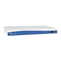
ADTRAN TRACER 6000 SERIES System Manual (132 pages)
ADTRAN Netwok Device Integrated System Manual
Brand:
ADTRAN
| Category:
Network Card
| Size: 1 MB
Table of Contents
Table of Contents
9
About this Manual
2
Revision History
3
Save These Important Safety Instructions
4
FCC-Required Information
5
System Description
11
This Section of Adtran's TRACER 6000 Series Integrated System Manual Is Designed for
11
TRACER 64X0 Systems
11
Use by Network Engineers, Planners, and Designers for Overview Information about the
11
Features and Benefits
12
System Overview
12
Operational
12
Available Interface Modules
13
T1 Network Module
13
Quad Ethernet Switch Module
13
TRACER 64X0 Systems
12
Configuration and Management
12
Microwave Path Engineering Basics
15
Explains the Basics of Analyzing a Wireless Microwave Link or Path. Defines Significant
15
Decibels
16
Calculating the Fade Margin
16
Line-Of-Sight
16
Terminology
16
Receiver Power
17
Antenna Gain
18
Figure 1. Example Microwave Path with Parameters
18
Table 1. Antenna Gain for Given Dish Diameters with K = 0.55 (Standard)
19
Table 2. Antenna Gain for Given Dish Diameters with K = 0.55 (Metric)
19
Table 3. Antenna Gain for Given Dish Diameters with K = 0.40 (Standard)
19
Table 4. Antenna Gain for Given Dish Diameters with K = 0.40 (Metric)
19
Transmitted Power (PT)
20
Carrier Wavelength (L)
20
Table 5. Transmit Power Reduction for Various Antennae Gains
20
Path Distance (D)
21
System Losses (L)
21
Table 6. Typical Coaxial Loss for Common Cable Types
21
Path Loss (LP)
22
Table 7. Path Loss for Given Path Lengths (Miles)
22
Receiver Sensitivity
23
Table 8. Path Loss for Given Path Lengths (Kilometers)
23
Table 9. Receiver Sensitivity for the TRACER 64X0
23
Antenna Information
24
Antenna Alignment
24
TRACER RSSI Test Points
24
Real-Time Signal Values
24
Antenna Beam Patterns
25
Fresnel Zones, Earth Curvature, and Antenna Heights
25
Figure 2. Typical Antenna Beam Pattern
25
Table 10. Minimum Antenna Height for Given Path Lengths (Miles and Ft)
26
Other Considerations
27
Path Availability
27
Table 11. Minimum Antenna Height for Given Path Lengths (Km and M)
27
Parameters and Makes Several Installation Recommendations
15
Engineering Guidelines
29
Into Their Networks
29
Provides Information to Assist Network Designers with Incorporating the TRACER 64X0 System
29
Section 3 Engineering Guidelines
29
Equipment Dimensions
30
Power Requirements
30
Reviewing the Front Panel Design
30
RSSI Monitoring Interface
31
Front Panel Leds
31
AUX RS232 Interface (RJ-45)
32
CRAFT Port (DB-9)
33
Reviewing the TRACER 64X0 Rear Panel Design
33
MGMT 10/100Baset/Tx Connection (RJ-48C)
34
DC Power Connection (Plug-In Terminal Block)
35
Fuse
35
Alarm Contacts (Plug-In Terminal Block)
35
Antenna Interface (N-Type Connector)
35
Network Module Interfaces
37
4Xt1 Module
37
Quad Ethernet Switch Module
37
4Xe1 Module with 120Ω Interface
38
4Xe1 Module with 75Ω Interface
38
At-A-Glance Specifications
40
Network Turnup Procedure
43
Provides Shipment Contents List, Grounding Instructions, Mounting Options, and Specifics of
43
Supplying Power to the Unit
43
Introduction
44
Tools Required
44
Unpack and Inspect the System
44
Contents of Shipment
44
Customer Provides
45
Base System
45
Channel Selection
46
Grounding Instructions
47
Mounting Options
48
Supplying Power to the Unit
48
Installing Modules
50
Instructions for Installing Network Modules
50
Connecting the Module Interfaces
51
Quad T1 Module Interfaces
51
Quad Ethernet Switch Module
51
Quad E1 (120Ω) Module Interfaces
51
Quad E1 (75Ω) Module Interfaces
51
User Interface Guide
53
Provides Detailed Descriptions of All Menu Options and Configuration Parameters Available for
53
The TRACER 64X0
53
Navigating the Terminal Menu
55
Terminal Menu Window
55
The TRACER 64X0
55
Moving through the Menus
56
Navigating Using the Keyboard Keys
56
The TRACER 64X0
56
Menu and System Control
56
Password Protection
56
The TRACER 64X0
57
Menu Descriptions
57
System Status
57
The TRACER 64X0
58
The TRACER 64X0
59
Main Menu
59
The TRACER 64X0
60
System Configuration
60
The TRACER 64X0
61
The TRACER 64X0
62
The TRACER 64X0
63
RF Link Configuration
63
The TRACER 64X0
64
The TRACER 64X0
65
RF Link Performance History (Main Screen)
65
The TRACER 64X0
66
RF Link Error History
66
RF Link Max/Min Received Power History
66
The TRACER 64X0
67
RF Link Min/Max Received Signal Quality History
67
The TRACER 64X0
69
Datapath Provisioning
69
The TRACER 64X0
70
4Xe1 Module Configuration/Status/History (Main Screen)
70
E1X Status/Configuration/Loopback
70
The TRACER 64X0
71
Interface Type
71
The TRACER 64X0
72
E1X Performance History
73
The TRACER 64X0
74
T1 Module Configuration/Status/History (Main Screen)
74
T1X Status/Configuration/Loopback
74
The TRACER 64X0
75
Ethernet Switch Module Configuration/Status/History (Main Screen)
78
Ethernet Switch Configuration
78
Ethernet Switch Status
79
The TRACER 64X0
80
Management/Utilities (Main Screen)
80
The TRACER 64X0
82
Ping Utility
82
Firmware Upgrade Utility
84
The TRACER 64X0
86
RF Link Management Bridge Configuration
86
The TRACER 64X0
87
System Alarms
87
The TRACER 64X0
88
Detail Level Procedures
89
Provides Detailed Instructions on Performing Common System Tasks such as Connecting to the
89
DLP-1 Connecting a VT100 Terminal or PC to the CRAFT Port
91
Tools and Materials Required
91
DLP-2 Logging into the TRACER 64X0
93
DLP-3 Setting IP Parameters for the TRACER 64X0
95
DLP-4 Verifying Communications over an IP LAN
99
DLP-5 Updating the Firmware Using TFTP
103
DLP-6 Updating the Firmware Using XMODEM
107
Mibs
109
Provides a Listing of SNMP Management Information Bases (Mibs) Supported by the
109
Section 7 Mibs
109
TRACER 64X0. this Section also Lists Traps Supported for each MIB
109
Troubleshooting Guide
125
Section 8 Troubleshooting Guide
125
Overview
126
LED Indicators
126
Pwr Led
126
Rf Dwn Led
126
TRACER 64X0
126
Tst Led
126
Rf Low Led
127
T1 Interface Alarms
127
E1 Interface Alarms
128
LAN Leds
129
System Alarms
129
RF Errors
129
Step-By-Step Troubleshooting
130
Installing/Troubleshooting the TRACER Hardware
130
Installing/Configuring T1 Hardware
132
Installing/Configuring E1 Hardware
132
Installing/Configuring Ethernet Hardware
132
Advertisement
ADTRAN TRACER 6000 SERIES User Manual (126 pages)
Brand:
ADTRAN
| Category:
Computer Hardware
| Size: 2 MB
Table of Contents
Table of Contents
9
System Description
11
System Overview
12
Features and Benefits
12
Configuration and Management
12
Operational
13
Available Interface Modules
13
T1 Network Module
13
Quad Ethernet Switch Module
13
Microwave Path Engineering Basics
15
Explains the Basics of Analyzing a Wireless Microwave Link or Path. Defines Significant
15
Parameters and Makes Several Installation Recommendations
15
Decibels
16
Calculating the Fade Margin
16
Line-Of-Sight
16
Terminology
16
Receiver Power
17
Antenna Gain
18
Figure 1. Example Microwave Path with Parameters
18
Table 1. Antenna Gain for Given Dish Diameters (Standard)
18
Transmitted Power (PT)
19
Carrier Wavelength (L)
19
Path Distance (D)
19
System Losses (L)
19
Table 2. Antenna Gain for Given Dish Diameters (Metric)
19
Path Loss (LP)
20
Table 3. Typical Coaxial Loss for Common Cable Types
20
Table 4. Path Loss for Given Path Lengths (Miles)
21
Table 5. Path Loss for Given Path Lengths (Kilometers)
21
Receiver Sensitivity
22
Antenna Information
22
Antenna Alignment
22
Table 6. Receiver Sensitivity for the TRACER 6320
22
TRACER RSSI Test Points
23
Antenna Beam Patterns
23
Fresnel Zones, Earth Curvature, and Antenna Heights
23
Figure 2. Typical Antenna Beam Pattern
23
Table 7. Minimum Antenna Height for Given Path Lengths (Standard)
24
Table 8. Minimum Antenna Height for Given Path Lengths (Metric)
25
Other Considerations
26
Path Availability
26
Engineering Guidelines
29
Provides Information to Assist Network Designers with Incorporating the TRACER 6000 Series
29
Section 3 Engineering Guidelines
29
Split System into Their Networks
29
Reviewing the Front Panel Design
31
RSSI Monitoring Interface
32
Front Panel Leds
32
AUX RS232 Interface (RJ-45)
32
CRAFT Port (DB-9)
33
Equipment Dimensions
31
Power Requirements
31
Reviewing the TRACER 6200 Rear Panel Design
34
MGMT 10/100Baset/Tx Connection (RJ-45)
35
DC Power Connection (Plug-In Terminal Block)
35
Fuse
35
Alarm Contacts (Plug-In Terminal Block)
35
To ODU Interface (N-Type Connector)
36
TRACER 6320 Outdoor Unit (ODU)
36
RSSI Monitoring Interface
37
To IDU
37
Network Module Interfaces
37
4Xe1 Module with 120Ω Interface
37
4Xe1 Module with 75Ω Interface
38
4Xt1 Module
39
Quad Ethernet Switch Module
40
At-A-Glance Specifications
40
Network Turnup Procedure
45
Provides Shipment Contents List, Grounding Instructions, Mounting Options, and Specifics of
45
Supplying Power to the Unit
45
Unpack and Inspect the System
46
Contents of Shipment
46
Customer Provides
47
Quad Ethernet Switch Module
48
Tools Required
46
Introduction
46
Grounding Instructions
48
Channel Selection
48
Supplying Power to the Unit
49
Mounting Options
50
Indoor Unit (IDU)
50
Outdoor Unit (ODU)
51
Installing Modules
52
Instructions for Installing Network Modules
53
Connecting the MODULE Interfaces
53
Quad T1 Module Interfaces
53
Quad E1 (120Ω) Module Interfaces
53
Quad E1 (75Ω) Module Interfaces
54
Quad Ethernet Switch Module
54
User Interface Guide
55
Provides Detailed Descriptions of All Menu Options and Configuration Parameters Available for
55
The TRACER 6000 Series Split System
55
Navigating the Terminal Menu
57
Terminal Menu Window
57
Navigating Using the Keyboard Keys
58
Menu and System Control
58
Password Protection
58
Menu Descriptions
59
System Status
59
Main Menu
61
System Configuration
62
RF Link Configuration
64
RF Link Performance History (Main Screen)
66
RF Link/Odu Error History
66
RF Link Max/Min Received Power History
67
RF Link Min/Max Received Signal Quality History
68
Datapath Provisioning
69
4Xe1 Module Configuration/Status/History (Main Screen)
70
E1X Status/Configuration/Loopback
70
E1X Performance History
73
T1 Module Configuration/Status/History (Main Screen)
74
T1X Status/Configuration/Loopback
74
Ethernet Switch Module Configuration/Status/History (Main Screen)
78
Ethernet Switch Configuration
78
Ethernet Switch Status
79
Management/Utilities (Main Screen)
80
Ping Utility
82
Firmware Upgrade Utility
84
RF Link Management Bridge Configuration
86
Detail Level Procedures
89
Provides Detailed Instructions on Performing Common System Tasks such as Connecting to the
89
DLP-1 Connecting a VT100 Terminal or PC to the CRAFT Port
91
DLP-2 Logging into the TRACER System
93
DLP-3 Setting IP Parameters for the TRACER System
95
DLP-4 Verifying Communications over an IP LAN
99
DLP-5 Updating the Firmware Using TFTP
101
DLP-6 Updating the Firmware Using XMODEM
105
Mibs
107
Section 7 Mibs
107
Provides a Listing of SNMP Management Information Bases (Mibs) Supported by the
107
TRACER 6000 Split System. this Section also Lists Traps Supported for each MIB
107
Troubleshooting Guide
119
Section 8 Troubleshooting Guide
119
Overview
120
LED Indicators
120
Pwr Led
120
Rf Dwn Led
120
TRACER 6000 Series
120
Tst Led
120
Rf Low Led
121
T1 Interface Alarms
121
E1 Interface Alarms
122
LAN Leds
123
RF Errors
123
Step-By-Step Troubleshooting
124
Installing/Troubleshooting the TRACER Hardware
124
Installing/Configuring T1 Hardware
125
Installing/Configuring E1 Hardware
126
Installing/Configuring Ethernet Hardware
126
Advertisement
Related Products
ADTRAN 239 T1 HDSL4
ADTRAN TSU ACE
ADTRAN TRACER Protection Switch
ADTRAN TSU 600
ADTRAN TR OCU DP
ADTRAN TRACER
ADTRAN TR DDS-DP
ADTRAN TRACER 4305
ADTRAN T200 FNID
ADTRAN Total Access QFO-C
ADTRAN Categories
Network Hardware
Network Router
Switch
Gateway
Control Unit
More ADTRAN Manuals
Login
Sign In
OR
Sign in with Facebook
Sign in with Google
Upload manual
Upload from disk
Upload from URL