Sign In
Upload
Manuals
Brands
ABB Manuals
Inverter
ACS880-07CLC
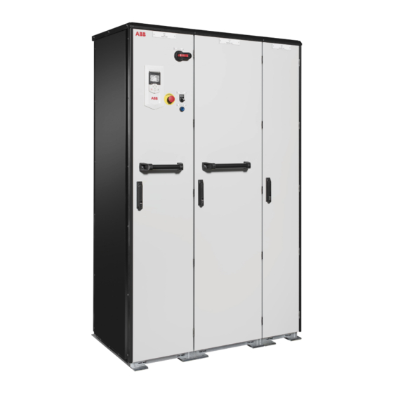
ABB ACS880-07CLC Manuals
Manuals and User Guides for ABB ACS880-07CLC. We have
7
ABB ACS880-07CLC manuals available for free PDF download: Firmware Manual, Hardware Manual, User Manual, Electrical Planning Instructions, Electrical Planning Manual
ABB ACS880-07CLC Firmware Manual (604 pages)
primary control program
Brand:
ABB
| Category:
Servo Drives
| Size: 5 MB
Table of Contents
Table of Contents
5
Safety Instructions
11
Target Audience
11
Introduction to the Manual
11
Applicability
11
What this Chapter Contains
11
Contents of the Manual
12
Related Documents
12
Terms and Abbreviations
13
Cybersecurity Disclaimer
16
Using the Control Panel
17
Control Locations and Operating Modes
19
What this Chapter Contains
19
Local Control Vs. External Control
20
Local Control
20
External Control
21
Operating Modes of the Drive
22
DC Voltage Control Mode
23
Special Control Modes
23
Torque Control Mode
23
Speed Control Mode
23
Frequency Control Mode
23
Program Features
25
What this Chapter Contains
25
Drive Configuration and Programming
26
Programming Via Parameters
26
Adaptive Programming
27
Application Programming
27
Programmable Digital Inputs and Outputs
28
Control Interfaces
28
Programmable Analog Outputs
28
Programmable Analog Inputs
28
Programmable Relay Outputs
29
Programmable I/O Extensions
29
Fieldbus Control
30
Master/Follower Functionality
31
External Controller Interface
39
Control of a Supply Unit (LSU)
41
Motor Control
42
Direct Torque Control (DTC)
42
Reference Ramping
42
Constant Speeds/Frequencies
43
Critical Speeds/Frequencies
43
Speed Controller Autotune
44
Oscillation Damping
47
Resonance Frequency Elimination
48
Rush Control
48
Encoder Support
49
Jogging
55
Scalar Motor Control
58
Autophasing
59
Flux Braking
62
DC Magnetization
63
Hexagonal Motor Flux Pattern
65
Process PID Control
66
Application Macros
66
Application Control
66
Motor Potentiometer
69
Mechanical Brake Control
70
DC Voltage Control
75
Overvoltage Control
75
Undervoltage Control (Power Loss Ride-Through)
75
Voltage Control and Trip Limits
76
Brake Chopper
77
DC Voltage Control Mode
78
Safety and Protections
79
Emergency Stop
79
Motor Thermal Protection
80
Motor Overload Protection
83
Thermal Protection of Motor Cable
84
User Load Curve
84
Automatic Fault Resets
85
Other Programmable Protection Functions
86
Maintenance Timers and Counters
88
Fault and Warning Messages, Data Logging
88
Signal Supervision
88
Diagnostics
88
Energy Saving Calculators
89
Load Analyzer
89
Miscellaneous
91
User Parameter Sets
91
Parameter Checksum Calculation
91
User Lock
92
Reduced Run Function
93
Data Storage Parameters
93
Du/Dt Filter Support
94
Sine Filter Support
95
Router Mode for BCU Control Unit
95
Application Macros
97
What this Chapter Contains
97
General
97
Factory Macro
98
Default Parameter Settings for the Factory Macro
98
Default Control Connections for the Factory Macro
99
Hand/Auto Macro
100
Default Parameter Settings for the Hand/Auto Macro
100
Default Control Connections for the Hand/Auto Macro
101
PID Control Macro
102
Default Parameter Settings for the PID Control Macro
103
Default Control Connections for the PID Control Macro
104
Sensor Connection Examples for the PID Control Macro
105
Torque Control Macro
106
Default Parameter Settings for the Torque Control Macro
106
Default Control Connections for the Torque Control Macro
107
Sequential Control Macro
108
Operation Diagram
108
Selection of Constant Speeds
109
Default Parameter Settings for the Sequential Control Macro
109
Default Control Connections for the Sequential Control Macro
110
Fieldbus Control Macro
111
Parameters
113
What this Chapter Contains
113
Terms and Abbreviations
114
Advertisement
ABB ACS880-07CLC Hardware Manual (280 pages)
Brand:
ABB
| Category:
DC Drives
| Size: 15 MB
Table of Contents
Table of Contents
5
Safety Instructions
15
Contents of this Chapter
15
Use of Warnings and Notes
15
General Safety in Installation, Start-Up and Maintenance
16
Work on the Liquid Cooling System
18
Electrical Safety in Installation, Start-Up and Maintenance
19
Electrical Safety Precautions
19
Additional Instructions and Notes
21
Printed Circuit Boards
21
Grounding
22
General Safety in Operation
23
Additional Instructions for Permanent Magnet Motor Drives
24
Safety in Installation, Start-Up, Maintenance
24
Safety in Operation
24
Introduction to the Manual
25
Contents of this Chapter
25
Target Audience
25
Categorization by Frame Size and Option Code
25
Use of Component Designations
26
Quick Installation, Commissioning and Operation Flowchart
26
Terms and Abbreviations
27
Related Manuals
27
Operation Principle and Hardware Description
29
Contents of this Chapter
29
Operation Principle
29
Charging
30
Overview Diagrams
31
Overview Diagram of the Drive
31
6-Pulse, 12-Pulse and 24-Pulse Connections
37
Cabinet Line-Up and Layout Examples
38
Overview of Power and Control Connections
41
Control Units
42
Door Devices
42
Control Panel
43
Control by PC Tools
43
Descriptions of Options
43
Degree of Protection
43
Definitions
43
Marine Construction (Option +C121)
44
UL Listed (Option +C129)
44
Plinth Height (Options +C164 and +C179)
44
Resistor Braking (Options +D150 and +D151)
44
D U /D T Filter (Option +E205)
44
Cabinet Heater with External Supply (Option +G300)
44
Cabinet Lighting (Option +G301)
45
Output for Motor Space Heater (Option +G313)
45
Halogen-Free Wiring and Materials (Option +G330)
45
Wire Markings
45
Standard Wiring
45
Additional Wire Markings
46
Bottom Cable Entry/Exit (Options +H350 and +H352)
47
Cable Conduit Entry (Option +H358)
47
Common Motor Terminal Cubicle (Option +H359)
47
Common Output Terminals (Option +H366)
47
Roxtec Cable Entry (Option +H394)
48
Additional Terminal Block X504 (Option +L504)
49
Starter for Auxiliary Motor Fan (Options +M600
49
What the Option Contains
49
Description
49
Type Designation Label
49
Type Designation Key
50
Option Codes
50
Mechanical Installation
55
Contents of this Chapter
55
Examining the Installation Site
55
Necessary Tools
55
Examining the Delivery
56
Moving and Unpacking the Drive
56
Moving the Drive in Its Packaging
57
Lifting the Crate with a Forklift
57
Lifting the Crate with a Crane
58
Moving the Crate with a Forklift
59
Removing the Transport Package
59
Moving the Unpacked Drive Cabinet
60
Lifting the Cabinet with a Crane
60
Moving the Cabinet on Rollers
60
Moving the Cabinet on Its Back
61
Moving the Cabinet to Its Final Position
61
Attaching the Cabinet to the Floor and Wall or Roof
62
General Rules
62
Attaching the Cabinet (Marine Units)
63
Joining Cabinet Sections Together
64
Miscellaneous
69
Cable Duct in the Floor below the Cabinet
69
Arc Welding
69
Lifting Lugs and Bars
70
Certificate of Conformity
70
Declarations of Conformity
70
Electrical Planning
75
Contents of this Chapter
75
Limitation of Liability
75
North America
75
Selecting the Supply Transformer
75
Selecting the Main Supply Disconnecting Device
77
Selecting the Main Contactor or Breaker
77
Examining the Compatibility of the Motor and Drive
78
Protecting the Motor Insulation and Bearings
78
Requirements Tables
78
Requirements for ABB Motors, P
79
Kw (134 Hp)
79
Requirements for ABB Motors, P
80
Kw (134 Hp)
80
Requirements for Non-ABB Motors, P
81
Kw (134 Hp)
81
Requirements for Non-ABB Motors, P
82
Kw (134 Hp)
82
Abbreviations
82
Availability of D U /D T Filter and Common Mode Filter by Drive Type
83
Additional Requirements for Explosion-Safe (EX) Motors
83
HX_ and am
83
Additional Requirements for Braking Applications
83
Additional Requirements for ABB High-Output and IP23 Motors
83
Additional Requirements for Non-ABB High-Output and IP23 Motors
83
Additional Data for Calculating the Rise Time and the Peak Line-To-Line Voltage
84
Additional Note for Sine Filters
85
Selecting the Power Cables
85
Power Cable Selection Procedure and Applicability Check
85
General Guidelines
86
Typical Power Cable Sizes
86
Power Cable Types
86
Preferred Power Cable Types
86
Alternate Power Cable Types
87
Not Allowed Power Cable Types
88
Power Cable Shield
88
Grounding Requirements
89
Additional Grounding Requirements - IEC
90
Additional Grounding Requirements - UL (NEC)
90
Selecting the Control Cables
90
Shielding
90
Signals in Separate Cables
91
Signals that Can be Run in the same Cable
91
Relay Cable
91
Control Panel to Drive Cable
91
PC Tool Cable
91
Routing the Cables
91
General Guidelines - IEC
91
The Motor Cable
92
Separate Control Cable Ducts
92
Roxtec Cable Entry (Option +H394)
93
Situations and against Thermal Overload
94
Protecting the Input Cabling and the Drive Upon a Short-Circuit
94
Protecting the Motor and Motor Cable in Short-Circuits
94
Protecting the Drive and the Power Cables against Thermal Overload
94
Protecting the Motor against Thermal Overload
94
Protecting the Motor against Overload Without Thermal Model or Temperature Sensors
95
Protecting the Drive against Ground Faults
95
Residual Current Device Compatibility
95
Implementing the Emergency Stop Function
95
Implementing the Safe Torque off Function
95
Implementing the Power Loss Ride-Through Function
96
Implementing a Bypass Connection
96
Supplying Power for the Auxiliary Circuits
96
Using Power Factor Compensation Capacitors with the Drive
97
Using a Safety Switch between the Drive and the Motor
97
Implementing the Control of a Contactor between Drive and Motor
97
Protecting the Contacts of Relay Outputs
98
Implementing a Motor Temperature Sensor Connection
98
Connecting a Motor Temperature Sensor to the Drive through an Option Module
99
Electrical Installation
101
Contents of this Chapter
101
Measuring the Insulation
101
Measuring the Insulation Resistance of the Drive
101
Measuring the Insulation Resistance of the Motor and Motor Cable
101
Measuring the Insulation Resistance of the Input Power Cable
102
Connecting the Motor Cables (Units Without Common Motor Terminal Cubicle)
103
Motor Connection Diagram (Without Option +H366)
103
Motor Connection Diagram (with Option +H366)
104
Procedure
105
Removing the Shrouds
105
Connecting the Cables
105
Installing the Fans and Shrouds
107
At the Motor End
108
Connecting the Motor Cables (Units with Common Motor Terminal Cubicle)
109
Output Busbars
109
Connection Diagram
109
Procedure
109
Removing Shrouds
109
Connecting the Cables
110
Installing Shrouds
111
Connecting an External Brake Resistor Assembly
111
Connecting the Input Power Cables
112
Connection Diagrams
112
Connection Diagram - 2×D8D, 6-Pulse, Internal Charging
112
Connection Diagram - 2×D8D, 12-Pulse, Internal Charging
113
Connection Diagram - 2×D8D, 6-Pulse, External Charging and Pre-Magnetizing
114
Connection Diagram - 2×D8D, 12-Pulse, External Charging and Pre-Magnetizing
115
Layout of the Input Cable Connection Terminals and Cable Entries
115
Connection Procedure
116
Removing Shrouds
116
Connecting the Cables
116
Installing Shrouds
118
Use of Fasteners in Cable Lug Connections
119
Connecting the Control Cables
120
Control Cable Connection Procedure
120
Grounding the Outer Shields of the Control Cables 360° at the Cabinet Entry
120
Routing the Control Cables Inside the Cabinet
122
Connecting Control Cabling
122
Connecting a PC
124
Panel Bus (Control of Several Units from One Control Panel)
125
Installing Option Modules
127
Installing Option Modules (UCU)
127
Mechanical Installation of I/O Extension, Fieldbus Adapter and Pulse Encoder
129
Interface Modules on BCU
129
Installation of an FSO Safety Functions Module Onto BCU Control Unit
131
Wiring of Option Modules
132
Control Unit (UCU)
133
General
133
Contents of this Chapter
133
Layout
134
Default I/O Diagram of the Inverter Control Unit
137
Additional Information on the Connections
141
Connecting Motor Temperature Sensors to the Drive
141
Power Supply for the Control Unit (XPOW)
141
Digital Interlock (DIIL)
141
The XD2D Connector
141
Safe Torque off (XSTO, XSTO OUT)
142
Safety Functions Module Connection (XFSO)
142
Microsdhc Memory Card Slot
142
Connector Data
142
Ground Isolation Diagram
145
Control Units (BCU and ZCU)
147
Contents of this Chapter
147
General
147
ZCU-14 Layout
148
ZCU-14 Default I/O Connection Diagram
149
Bcu
151
Layout
151
Default I/O Diagram of the Inverter Control Unit (BCU)
153
BCU, ZCU-14 Connections Additional Info
157
Additional Information on the Connections
157
Connecting Motor Temperature Sensors to the Drive
157
Power Supply for the Control Unit (XPOW)
157
Digital Interlock (DIIL)
157
The XD2D Connector
157
Safe Torque off (XSTO, XSTO OUT)
158
FSO Safety Functions Module Connection (X12)
158
SDHC Memory Card Slot
158
BCU, ZCU-14 Connector Data
158
Connector Data
158
BCU Ground Isolation Diagram
161
ZCU Ground Isolation Diagram
162
Installation Checklist
163
Contents of this Chapter
163
Checklist
163
Start-Up
165
Contents of this Chapter
165
Start-Up Procedure
165
Switching off the Drive
167
Maintenance
169
Contents of this Chapter
169
Maintenance Intervals
169
Description of Symbols
169
Recommended Maintenance Intervals after Start-Up
169
Cooling Fans
171
Replacing the Cooling Fan in the Supply Module Cubicle
171
Replacing the Cooling Fan of an Inverter Module
172
Replacing the Common Motor Terminal Cubicle Fan
173
Fuses
174
Replacing the AC Fuses
174
ABB ACS880-07CLC Hardware Manual (214 pages)
Brand:
ABB
| Category:
Inverter
| Size: 8 MB
Table of Contents
Effective: 2018
3
Table of Contents
5
1 Safety Instructions
13
Contents of this Chapter
13
Use of Warnings and Notes
13
General Safety in Installation, Start-Up and Maintenance
14
Work on the Liquid Cooling System
15
Electrical Safety in Installation, Start-Up and Maintenance
16
Electrical Safety Precautions
16
Additional Instructions and Notes
18
Optical Components
18
Printed Circuit Boards
18
Grounding
18
Additional Instructions for Permanent Magnet Motor Drives
19
Safety in Installation, Start-Up, Maintenance
19
Safety in Operation
20
2 Introduction to the Manual
21
Contents of this Chapter
21
Target Audience
21
Categorization by Frame Size and Option Code
21
Use of Component Designations
22
Quick Installation, Commissioning and Operation Flowchart
22
Terms and Abbreviations
23
Related Manuals
23
3 Operation Principle and Hardware Description
25
Contents of this Chapter
25
Operation Principle
25
Charging
26
Overview Diagrams
27
Overview Diagram of the Drive
27
6-Pulse, 12-Pulse and 24-Pulse Connections
32
Cabinet Line-Up and Layout Examples
34
Overview of Power and Control Connections
37
Door Switches and Lights
38
Control Panel
38
Control by PC Tools
39
Descriptions of Options
40
Degree of Protection
40
Definitions
40
Marine Construction (Option +C121)
40
Plinth Height (Options +C164 and +C179)
40
Resistor Braking (Options +D150 and +D151)
40
Cabinet Heater with External Supply (Option +G300)
40
Cabinet Lighting (Option +G301)
41
Output for Motor Space Heater (Option +G313)
41
Halogen-Free Wiring and Materials (Option +G330)
41
Additional Wire Markings
41
Standard Wire Markings
41
Cable Conduit Entry (Option +H358)
43
Common Motor Terminal Cubicle (Option +H359)
43
Common Output Terminal (Option +H366)
43
Additional Terminal Block X504 (Option +L504)
44
Starter for Auxiliary Motor Fan (Options +M6Xx)
44
What the Option Contains
44
Description
44
Type Designation Label
45
Type Designation Key
45
4 Mechanical Installation
49
Contents of this Chapter
49
Examining the Installation Site
49
Necessary Tools
49
Checking the Delivery
50
Moving and Unpacking the Drive
51
Moving the Drive in Its Packaging
51
Lifting the Crate with a Forklift
51
Lifting the Crate with a Crane
52
Moving the Crate with a Forklift
53
Removing the Transport Package
53
Moving the Unpacked Drive Cabinet
54
Lifting the Cabinet with a Crane
54
Moving the Cabinet on Rollers
55
Moving the Cabinet on Its Back
55
Final Placement of the Cabinet
56
Fastening the Cabinet to the Floor and Wall or Roof
57
General Rules
57
Fastening the Cabinet (Marine Units)
58
Joining Cabinet Sections Together
59
Miscellaneous
63
Cable Duct in the Floor below the Cabinet
63
Arc Welding
63
5 Guidelines for Planning the Electrical Installation
65
Contents of this Chapter
65
Limitation of Liability
65
Selecting the Supply Transformer
65
Selecting the Main Disconnecting Device
65
Selecting the Main Contactor or Breaker
66
Examining the Compatibility of the Motor and Drive
66
Protecting the Motor Insulation and Bearings
66
Requirements Table
67
Availability of Du/Dt Filter and Common Mode Filter by Drive Type
69
Additional Requirements for Explosion-Safe (EX) Motors
69
And am
69
Additional Requirements for Braking Applications
69
Additional Requirements for ABB High-Output and IP23 Motors
69
Additional Requirements for Non-ABB High-Output and IP23 Motors
69
Additional Data for Calculating the Rise Time and the Peak Line-To-Line Voltage
70
Selecting the Power Cables
71
General Rules
71
Typical Power Cable Sizes
72
Alternative Power Cable Types
72
Recommended Power Cable Types
72
Not Allowed Power Cable Types
73
Power Cable Shield
73
Planning the Resistor Braking System
74
Selecting the Control Cables
74
Shielding
74
Signals in Separate Cables
74
Signals Allowed to be Run in the same Cable
74
Relay Cable Type
75
Control Panel Cable Length and Type
75
Routing the Cables
75
Separate Control Cable Ducts
76
Continuous Motor Cable Shield or Enclosure for Equipment on the Motor Cable
76
Implementing Thermal Overload and Short-Circuit Protection
76
Protecting the Input Cabling and the Drive Upon a Short-Circuit
76
Protecting the Motor and Motor Cable in Short-Circuits
76
Protecting the Drive and the Power Cables against Thermal Overload
76
Protecting the Motor against Thermal Overload
77
Protecting the Drive against Ground Faults
77
Residual Current Device Compatibility
77
Implementing the Emergency Stop Function
77
Implementing the Safe Torque off Function
78
Implementing the Power-Loss Ride-Through
78
Implementing a Bypass Connection
78
Supplying Power for the Auxiliary Circuits
78
Using Power Factor Compensation Capacitors with the Drive
78
Using a Safety Switch between the Drive and the Motor
79
Protecting the Contacts of Relay Outputs
79
Implementing a Motor Temperature Sensor Connection
80
Connection of Motor Temperature Sensor to the Drive Via an Option Module
81
6 Electrical Installation
83
Contents of this Chapter
83
Warnings
83
Checking the Insulation of the Drive
83
Connecting the Control Cables
84
Control Cable Connection Procedure
84
Grounding the Outer Shields of the Control Cables at the Cabinet Entry
84
Routing the Control Cables Inside the Cabinet
86
Connecting Control Cabling
86
Connecting the Motor Cables (Units Without Common Motor Terminal Cubicle)
88
Motor Connection Diagram (Without Option +H366)
88
Motor Connection Diagram (with Option +H366)
89
Procedure
89
Connecting the Motor Cables (Units with Common Motor Terminal Cubicle)
92
Output Busbars
92
Connection Diagram
92
Procedure
92
Connecting an External Brake Resistor Assembly
93
Connecting the Input Power Cables
94
Connection Diagrams
94
Connection Diagram - 2×D8D, 6-Pulse, Internal Charging
94
Connection Diagram - 2×D8D, 12-Pulse, Internal Charging
95
Connection Diagram - 2×D8D, 6-Pulse, External Charging and Pre-Magnetizing
96
Connection Diagram - 2×D8D, 12-Pulse, External Charging and Pre-Magnetizing
97
Layout of the Input Cable Connection Terminals and Cable Entries
97
Connection Procedure
97
Connecting a PC
100
Panel Bus (Control of Several Units from One Control Panel)
100
Installing Option Modules
101
Mechanical Installation of I/O Extension, Fieldbus Adapter and Pulse Encoder Interface Modules
101
Wiring of Optional Modules
102
7 Control Units of the Drive
103
Contents of this Chapter
103
General
103
ZCU-14 Layout and Connections
104
ZCU-14 Default I/O Connection Diagram
105
BCU-X2 Control Unit Layout and Connections
107
Default I/O Diagram of the Inverter Control Unit (A41)
109
External Power Supply for the Control Unit (XPOW)
110
DI6 as a PTC Sensor Input
110
AI1 or AI2 as a Pt100, Pt1000, PTC or KTY84 Sensor Input
111
DIIL Input
111
Drive-To-Drive Link (XD2D)
111
Safe Torque off (XSTO, XSTO OUT)
112
FSO-XX Safety Functions Module Connection (X12)
112
SDHC Memory Card Slot
112
Connector Data
113
BCU-X2 Ground Isolation Diagram
115
Ground Isolation Diagram
116
8 Installation Checklist
117
Contents of this Chapter
117
Checklist
117
9 Start-Up
119
Contents of this Chapter
119
Start-Up Procedure
119
10 Fault Tracing
123
Contents of this Chapter
123
Leds
123
Warning and Fault Messages
123
11 Maintenance
125
Contents of this Chapter
125
Maintenance Intervals
125
Power Connections and Quick Connectors
126
Retightening the Power Connections
126
Cooling Fans
127
Replacing the Cooling Fan in the Supply Module Cubicle
127
Replacing the Cooling Fan of an Inverter Module
128
Fuses
129
Replacing the AC Fuses
129
Replacing the DC Fuses
130
Supply and Inverter Modules
131
Replacing a Supply Module
131
Replacing an Inverter Module
134
Removing the Module
134
Reinstalling the Module
136
Activating the Reduced Run of the Inverter Unit
136
Returning the Module
138
Capacitors
138
Reforming the Capacitors
139
Control Panel
139
Replacing the Control Panel Battery
139
Cleaning the Control Panel
139
Control Units
140
BCU Control Unit Types
140
Replacing the Memory Unit
140
Replacing the BCU Control Unit Battery
140
Advertisement
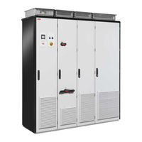
ABB ACS880-07CLC User Manual (80 pages)
Industrial Drives, ATEX-certified motor thermal protection functions for cabinet-built ACS880 drives (options +L513+Q971 and +L514+Q971)
Brand:
ABB
| Category:
DC Drives
| Size: 6 MB
Table of Contents
Table of Contents
5
1 Introduction to the Manual
9
Contents of this Chapter
9
Applicability
9
Safety Instructions
9
Example Circuit Diagrams of this Manual
10
Commissioning the Drive for a Motor in a Hazardous Area
11
Minimum Switching Frequency
11
Target Audience
11
Contents
11
Related Documents
11
Terms and Abbreviations
12
Exclusion of Liability
13
2 ATEX-Certified Motor Thermal Protection Function with PTC Thermistor Relays
15
Contents of this Chapter
15
Description
16
Operation Principle
17
Without an FSO Module
17
With an FSO Module
18
Resetting the ATEX-Certified Motor Thermal Protection Function
19
Indications of the ATEX-Certified Motor Thermal Protection Function
19
PTC Thermistor Relays
20
ABB CM-MSS.41 Thermistor Motor Protection Relay
21
Layout
21
Operation Diagram
21
DOLD MK 9163N.12/110-ATEX Thermistor Relay
22
Layout
22
Operation Diagram
22
Wiring
23
General Wiring Instructions
23
Wiring Example
24
Start-Up and Acceptance Test
25
Checks and Settings with no Voltage Connected
25
Settings with Voltage Connected
25
Acceptance Test Procedure
25
Maintenance
26
Fault Tracing
26
Safety Data and Block Diagrams
27
Without an FSO Module
27
With an FSO Module
27
3 ATEX-Certified Motor Thermal Protection Function with Pt100 Relays (+L514+Q971)
29
Contents of this Chapter
29
Description
30
General
30
Pt100 Relays
31
Operation Principle
32
Without an FSO Module
32
With an FSO Module
33
Resetting the ATEX-Certified Motor Thermal Protection Function
34
Indications of the ATEX-Certified Motor Thermal Protection Function
34
Pt100 Relays
35
GM International D1073S Relay (Programmable)
35
Layout
35
Prelectronics 9116B1 Universal Converter Relay (Programmable)
36
Layout
36
Pt100 Relay Programming
36
Wiring
37
General Wiring Instructions
37
Wiring Example
38
Start-Up and Acceptance Test
39
Checks and Settings with no Voltage Connected
39
Settings with Voltage Connected
39
Acceptance Test Procedure
39
Maintenance
40
Fault Tracing
40
Safety Data
41
Without an FSO Module
41
With an FSO Module
41
ABB ACS880-07CLC Electrical Planning Instructions (52 pages)
Multidrive cabinets and modules
Brand:
ABB
| Category:
Industrial Electrical
| Size: 2 MB
Table of Contents
Table of Contents
5
1 Introduction to the Manual
9
Contents of this Chapter
9
Applicability
9
Target Audience
9
Terms and Abbreviations
9
Related Manuals
11
Cabinet-Installed Multidrive Manuals
11
Multidrive Module Manuals
11
2 Electrical Planning Guidelines
13
Contents of this Chapter
13
Limitation of Liability
13
Selecting the Supply Disconnecting Device
13
Cabinet-Installed Multidrives
13
Multidrive Modules
13
Selecting the Main Contactor (Breaker)
14
Cabinet-Installed Multidrives
14
Multidrive Modules
14
Selecting the Supply Transformer
15
Basic Guidelines
15
Additional Notes
16
A Drive Larger than 500 Kva with an IGBT Supply Unit or a Regenerative Rectifier Unit
16
A Drive with a 12-Pulse Diode Supply Unit
17
Two Parallel-Connected Supply Units
17
Examining the Compatibility of the Motor and Drive
18
Protecting the Motor Insulation and Bearings
18
Requirements Table
18
Availability of Du/Dt Filter and Common Mode Filter by Drive Type
21
Additional Requirements for Explosion-Safe (EX) Motors
21
And am
21
Additional Requirements for Braking Applications
21
Additional Requirements for Drives with an IGBT Supply Unit or Regenerative Rectifier Unit
21
Additional Requirements for ABB High-Output and IP23 Motors
21
Additional Requirements for Non-ABB High-Output and IP23 Motors
22
Additional Data for Calculating the Rise Time and the Peak Line-To-Line Voltage
23
Additional Note for Sine Filters
23
Selecting the Power Cables
24
General Rules
24
Typical Power Cable Sizes
24
Alternative Power Cable Types
25
Recommended Power Cable Types
25
Power Cable Types for Limited Use
25
Not Allowed Power Cable Types
26
Power Cable Shield
26
Additional US Requirements
27
Metal Conduit
27
Selecting the Control Cables
28
Shielding
28
Signals in Separate Cables
28
Signals that Can be Run in the same Cable
28
Relay Cable Type
28
Control Panel Cable Length and Type
28
Routing the Cables
29
Guidelines for Routing the Cables
29
Separate Control Cable Ducts
30
Continuous Motor Cable Shield or Enclosure for Equipment on the Motor Cable
30
Implementing Thermal Overload and Short Circuit Protections
31
Protecting the Input Power Cable against Thermal Overload
31
Protecting the Input Power Cable in Short-Circuits
31
Protecting the Drive against Thermal Overload
31
Cabinet-Installed Multidrives
31
Multidrive Modules
31
Protecting against Short-Circuit Inside the Drive
31
Multidrive Modules
32
Protecting the Motor and Motor Cable in Short-Circuits
32
Protecting the Motor Cables against Thermal Overload
32
Protecting the Motor against Thermal Overload
32
Implementing a Motor Temperature Sensor Connection
33
Connection of Motor Temperature Sensor to the Drive Via an Option Module
33
Implementing a Ground Fault Protecting Function
34
Cabinet-Installed Multidrives
34
Residual Current Device Compatibility
34
Multidrives Modules
34
Implementing the Emergency Stop Function
35
Cabinet-Installed Multidrives
35
Multidrive Modules
35
Implementing the Safe Torque off Function
35
Implementing the Prevention of Unexpected Start-Up Function
36
Cabinet-Installed Multidrives
36
Multidrive Modules
36
Implementing the Safely-Limited Speed Function
36
Implementing the Functions Provided by the FSO-XX Safety Functions Module
36
Multidrive Modules
37
Supplying Power for the Auxiliary Circuits
37
Cabinet-Installed Multidrives
37
Using Power Factor Compensation Capacitors with the Drive
37
Using a Safety Switch between the Drive and the Motor
37
Implementing the Power-Loss Ride-Through
38
Cabinet-Installed Drives with Main Contactor (Option +F250)
38
Implementing the Control of a Contactor between Drive and Motor
38
Implementing a Bypass Connection
39
Protecting the Contacts of Relay Outputs
39
ABB ACS880-07CLC Electrical Planning Manual (50 pages)
liquid-cooled multidrive cabinets and modules
Brand:
ABB
| Category:
Industrial Equipment
| Size: 1 MB
Table of Contents
Table of Contents
5
Introduction to the Manual
9
Contents of this Chapter
9
Applicability
9
Safety Instructions
9
Target Audience
9
Terms and Abbreviations
10
Related Documents
11
Cabinet-Installed Multidrive Manuals
11
Multidrive Module Manuals
11
Electrical Planning Guidelines
13
Contents of this Chapter
13
Limitation of Liability
13
Selecting the Supply Disconnecting Device
13
Cabinet-Installed Multidrives
13
Multidrive Modules
13
European Union
13
North America
14
Other Regions
14
Selecting the Main Contactor (Breaker)
14
Cabinet-Installed Multidrives
14
Multidrive Modules
14
Selecting the Supply Transformer
15
Cabinet-Installed Multidrives
15
Basic Guidelines
15
Additional Notes
16
Multidrive Modules
17
IGBT Supply Modules ACS880-204LC
17
Diode Supply Modules ACS880-304LC+A019
17
Examining the Compatibility of the Motor and Drive
18
Protecting the Motor Insulation and Bearings
18
Requirements Table
18
Availability of Du/Dt Filter and Common Mode Filter by Drive or Inverter Type
21
Additional Requirements for Explosion-Safe (EX) Motors
21
And am
21
Additional Requirements for Braking Applications
21
Additional Requirements for Drives with an IGBT Supply Unit or Regenerative Rectifier Unit
21
Additional Requirements for ABB High-Output and IP23 Motors
21
Additional Requirements for Non-ABB High-Output and IP23 Motors
22
Additional Note for Sine Filters
22
Selecting the Power Cables
23
General Guidelines
23
Typical Power Cable Sizes
23
Power Cable Types
24
Recommended Power Cable Types
24
Alternate Power Cable Types
24
Not Allowed Power Cable Types
25
Power Cable Shield
25
Selecting the Control Cables
27
Shielding
27
Signals in Separate Cables
27
Signals that Can be Run in the same Cable
27
Relay Cable Type
27
Control Panel to Drive Connection
27
Routing the Cables
28
General Guidelines, IEC
28
Continuous Motor Cable Shield or Enclosure for Equipment on the Motor Cable
28
Separate Control Cable Ducts
29
Implementing Thermal Overload and Short Circuit Protections
30
Protecting the Input Power Cable against Thermal Overload
30
Diode Supply Unit
30
IGBT Supply Unit
30
Protecting the Input Power Cable in Short-Circuits
30
Protecting the Drive against Thermal Overload
30
Cabinet-Installed Multidrives
30
Multidrive Modules
30
Protecting against Short-Circuit Inside the Drive
31
Cabinet-Installed Multidrives
31
Multidrive Modules
31
Protecting the Motor and Motor Cable in Short-Circuits
31
ABB ACS880-07CLC User Manual (40 pages)
Emergency stop, stop category 0 (option +Q951) for ACS880-07CLC drives
Brand:
ABB
| Category:
DC Drives
| Size: 0 MB
Table of Contents
Table of Contents
5
1 Safety Instructions
7
Contents of this Chapter
7
Use of Warnings and Notes
7
Instructions for Functional Safety Circuits
8
Electrical Safety Precautions
9
2 Introduction to the Manual
11
Contents of this Chapter
11
Applicability
11
Target Audience
11
Exclusion of Liability
11
Quick Reference Guide for Taking a Safety Function into Use
12
Related Documents
12
Terms and Abbreviations
13
3 Option Description
15
Contents of this Chapter
15
Overview
15
Operation Principle
15
Fault Reaction Function
17
Hardware Settings
17
4 Electrical Installation
19
Contents of this Chapter
19
Wiring
19
5 Parameter Settings
21
Contents of this Chapter
21
Inverter Unit Parameter Settings
21
Supply Unit Parameter Settings
21
6 Use of the Safety Function
23
Contents of this Chapter
23
Activating the Safety Function
23
Resetting the Safety Function
23
7 Start-Up and Validation Test
25
Contents of this Chapter
25
Validation of the Safety Functions
25
Competence
25
Validation Procedure
25
Validation Test Reports
26
Start-Up and Validation Test
26
8 Fault Tracing
29
Contents of this Chapter
29
Reporting Problems and Failures Related to Safety Functions
30
9 Maintenance
31
Contents of this Chapter
31
Safety Circuit Maintenance
31
Proof Test Interval
31
Functional Safety Components
32
Competence
32
Residual Risk
32
Intentional Misuse
33
Decommissioning
33
Advertisement
Related Products
ABB ACS880-107LC
ABB ACS800-104
ABB ACS355-03E-38A0-4
ABB ACS355-03E-31A0-4
ABB ACS355-03E-03A3-4
ABB ACS355-03E-05A6-4
ABB ACS355-03E-15A6-4
ABB ACS355-03E-01A2-4
ABB ACS355-03E-12A5-4
ABB ACS350 Series
ABB Categories
Industrial Equipment
Controller
Measuring Instruments
Battery Charger
DC Drives
More ABB Manuals
Login
Sign In
OR
Sign in with Facebook
Sign in with Google
Upload manual
Upload from disk
Upload from URL