Sign In
Upload
Manuals
Brands
ABB Manuals
Inverter
ACS880-107LC
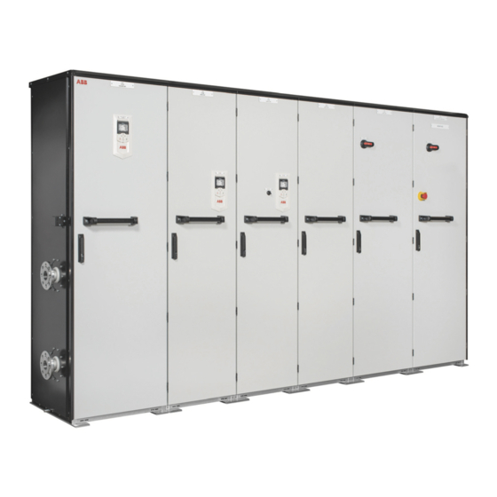
ABB ACS880-107LC Inverter Modules Manuals
Manuals and User Guides for ABB ACS880-107LC Inverter Modules. We have
3
ABB ACS880-107LC Inverter Modules manuals available for free PDF download: Firmware Manual, Hardware Manual
ABB ACS880-107LC Firmware Manual (604 pages)
primary control program
Brand:
ABB
| Category:
Servo Drives
| Size: 5 MB
Table of Contents
Table of Contents
5
Safety Instructions
11
Target Audience
11
Introduction to the Manual
11
Applicability
11
What this Chapter Contains
11
Contents of the Manual
12
Related Documents
12
Terms and Abbreviations
13
Cybersecurity Disclaimer
16
Using the Control Panel
17
Control Locations and Operating Modes
19
What this Chapter Contains
19
Local Control Vs. External Control
20
Local Control
20
External Control
21
Operating Modes of the Drive
22
DC Voltage Control Mode
23
Special Control Modes
23
Torque Control Mode
23
Speed Control Mode
23
Frequency Control Mode
23
Program Features
25
What this Chapter Contains
25
Drive Configuration and Programming
26
Programming Via Parameters
26
Adaptive Programming
27
Application Programming
27
Programmable Digital Inputs and Outputs
28
Control Interfaces
28
Programmable Analog Outputs
28
Programmable Analog Inputs
28
Programmable Relay Outputs
29
Programmable I/O Extensions
29
Fieldbus Control
30
Master/Follower Functionality
31
External Controller Interface
39
Control of a Supply Unit (LSU)
41
Motor Control
42
Direct Torque Control (DTC)
42
Reference Ramping
42
Constant Speeds/Frequencies
43
Critical Speeds/Frequencies
43
Speed Controller Autotune
44
Oscillation Damping
47
Resonance Frequency Elimination
48
Rush Control
48
Encoder Support
49
Jogging
55
Scalar Motor Control
58
Autophasing
59
Flux Braking
62
DC Magnetization
63
Hexagonal Motor Flux Pattern
65
Process PID Control
66
Application Macros
66
Application Control
66
Motor Potentiometer
69
Mechanical Brake Control
70
DC Voltage Control
75
Overvoltage Control
75
Undervoltage Control (Power Loss Ride-Through)
75
Voltage Control and Trip Limits
76
Brake Chopper
77
DC Voltage Control Mode
78
Safety and Protections
79
Emergency Stop
79
Motor Thermal Protection
80
Motor Overload Protection
83
Thermal Protection of Motor Cable
84
User Load Curve
84
Automatic Fault Resets
85
Other Programmable Protection Functions
86
Maintenance Timers and Counters
88
Fault and Warning Messages, Data Logging
88
Signal Supervision
88
Diagnostics
88
Energy Saving Calculators
89
Load Analyzer
89
Miscellaneous
91
User Parameter Sets
91
Parameter Checksum Calculation
91
User Lock
92
Reduced Run Function
93
Data Storage Parameters
93
Du/Dt Filter Support
94
Sine Filter Support
95
Router Mode for BCU Control Unit
95
Application Macros
97
What this Chapter Contains
97
General
97
Factory Macro
98
Default Parameter Settings for the Factory Macro
98
Default Control Connections for the Factory Macro
99
Hand/Auto Macro
100
Default Parameter Settings for the Hand/Auto Macro
100
Default Control Connections for the Hand/Auto Macro
101
PID Control Macro
102
Default Parameter Settings for the PID Control Macro
103
Default Control Connections for the PID Control Macro
104
Sensor Connection Examples for the PID Control Macro
105
Torque Control Macro
106
Default Parameter Settings for the Torque Control Macro
106
Default Control Connections for the Torque Control Macro
107
Sequential Control Macro
108
Operation Diagram
108
Selection of Constant Speeds
109
Default Parameter Settings for the Sequential Control Macro
109
Default Control Connections for the Sequential Control Macro
110
Fieldbus Control Macro
111
Parameters
113
What this Chapter Contains
113
Terms and Abbreviations
114
Parameters 115 Summary of Parameter Groups
115
Summary of Parameter Groups
115
Actual Values
117
Parameter Listing
117
Input References
121
Warnings and Faults
123
Diagnostics
129
Control and Status Words
130
System Info
145
Standard DI, RO
148
Standard DIO, FI, FO
154
Standard AI
159
Standard AO
163
O Extension Module 1
167
O Extension Module 2
186
O Extension Module 3
190
Operation Mode
194
Start/Stop/Direction
196
Start/Stop Mode
205
Speed Reference Selection
212
Speed Reference Ramp
220
Speed Reference Conditioning
226
Speed Control
231
Torque Reference Chain
242
Frequency Reference Chain
250
Voltage Reference Chain
258
Limits
263
Fault Functions
271
Supervision
282
Generic Timer & Counter
285
Motor Thermal Protection
293
Load Analyzer
304
User Load Curve
308
Process PID Set 1
311
Process PID Set 2
324
Brake Chopper
326
Mechanical Brake Control
328
Energy Efficiency
332
Monitoring/Scaling Settings
335
Data Storage
339
Panel Port Communication
342
Fieldbus Adapter (FBA)
344
FBA a Settings
352
FBA a Data in
353
FBA a Data out
354
FBA B Settings
354
FBA B Data in
355
Embedded Fieldbus
356
FBA B Data out
356
DDCS Communication
364
D2D and DDCS Transmit Data
377
D2D and DDCS Receive Data
381
Feedback Selection
389
Encoder Module Settings
398
Encoder 1 Configuration
401
Encoder 2 Configuration
407
LSU Control
409
HW Configuration
411
System
418
Motor Control
429
User Motor Parameters
433
Motor Data
435
O Bus Configuration
442
O Bus Diagnostics
442
O Bus Fan Identification
442
O Bus Service
442
Safety
442
Additional Parameter Data
443
Terms and Abbreviations
443
What this Chapter Contains
443
Parameter Groups 1
444
Parameter Groups 10
450
Speed Control
463
Speed Reference Conditioning
463
Torque Reference Chain
464
Frequency Reference Chain
465
Voltage Reference Chain
466
Limits
467
Fault Functions
468
Generic Timer & Counter
469
Supervision
469
Motor Thermal Protection
470
Load Analyzer
471
User Load Curve
472
Brake Chopper
476
Energy Efficiency
476
Mechanical Brake Control
476
Data Storage
477
Monitoring/Scaling Settings
477
Panel Port Communication
478
FBA a Data in
480
FBA a Data out
480
FBA a Settings
480
FBA B Settings
480
Embedded Fieldbus
481
FBA B Data in
481
FBA B Data out
481
DDCS Communication
482
D2D and DDCS Transmit Data
483
D2D and DDCS Receive Data
485
Feedback Selection
487
Encoder 1 Configuration
489
Encoder Module Settings
489
Encoder 2 Configuration
490
LSU Control
491
HW Configuration
492
System
492
User Motor Parameters
494
O Bus Configuration
495
O Bus Service
495
Safety
495
Fault Tracing
497
Indications
497
Safety
497
Warnings and Faults
497
What this Chapter Contains
497
Editable Messages
498
Event Logs
498
Pure Events
498
Warning/Fault History and Analysis
498
Other Data Loggers
499
Parameters that Contain Warning/Fault Information
499
QR Code Generation for Mobile Service Application
500
Warning Messages
501
Fault Messages
519
Auxiliary Codes for Line-Side Converter Warnings
539
Auxiliary Codes for Line-Side Converter Faults
541
Fieldbus Control through the Embedded Fieldbus Interface (EFB)
545
System Overview
545
What this Chapter Contains
545
Connecting the Fieldbus to the Drive
546
Setting up the Embedded Fieldbus Interface
547
Setting the Drive Control Parameters
548
Basics of the Embedded Fieldbus Interface
551
Actual Values
552
Control Word and Status Word
552
Data Input/Outputs
552
References
552
Register Addressing
553
About the Control Profiles
554
Control Word
555
The ABB Drives Profile
555
Status Word
557
State Transition Diagram
558
References
559
Actual Values
560
Modbus Holding Register Addresses
561
The Transparent Profile
562
Modbus Function Codes
563
Exception Codes
564
Coils (0Xxxx Reference Set)
565
Discrete Inputs (1Xxxx Reference Set)
566
Error Code Registers (Holding Registers 400090
568
Fieldbus Control through a Fieldbus Adapter
569
System Overview
569
What this Chapter Contains
569
Basics of the Fieldbus Control Interface
571
Control Word and Status Word
572
References
572
Actual Values
573
Contents of the Fieldbus Control Word (ABB Drives Profile)
575
Contents of the Fieldbus Status Word (ABB Drives Profile)
576
The State Diagram (ABB Drives Profile)
577
Setting up the Drive for Fieldbus Control
578
Parameter Setting Example: FPBA (PROFIBUS DP)
579
Control Chain Diagrams
581
What this Chapter Contains
581
Speed Reference Source Selection I
582
Speed Reference Source Selection II
583
Speed Reference Ramping and Shaping
584
Motor Feedback Configuration
585
Load Feedback and Position Counter Configuration
586
Speed Error Calculation
587
Speed Controller
588
Torque Reference Source Selection and Modification
589
Operating Mode Selection
590
Reference Selection for Torque Controller
591
Torque Limitation
592
Torque Controller
593
Frequency Reference Selection
594
Frequency Reference Modification
595
DC Voltage Reference Selection
596
DC Voltage Reference Modification
597
Process PID Setpoint and Feedback Source Selection
598
Process PID Controller
599
Master/Follower Communication I (Master)
600
Master/Follower Communication II (Follower)
601
Advertisement
ABB ACS880-107LC Hardware Manual (202 pages)
INDUSTRIAL DRIVES, INVERTER UNITS
Brand:
ABB
| Category:
Inverter Drive
| Size: 14 MB
Table of Contents
Table of Contents
5
Introduction to the Manual
11
Contents of this Chapter
11
Applicability
11
Safety Instructions
11
Target Audience
11
Categorization by Frame Size and Option Code
12
Use of Component Designations
12
Related Documents
12
Terms and Abbreviations
13
Operation Principle and Hardware Description
15
Contents of this Chapter
15
Overview Diagram of the Drive System
15
Inverter Unit Hardware
17
General
17
Inverter Module Hardware
17
Frame R7I
17
Control Unit
17
Module Layout
18
Coolant Connectors
18
Connectors X50, X52 and X53; Auxiliary Voltage Selector X59
18
Fiber Optic Connectors
20
Leds
20
Cabinet Layout
21
Frame R8I and Multiples
22
Control Unit
22
Module Layout
23
Coolant Connectors
23
Connectors X50
24
Fiber Optic Connectors
25
Cabinet Layout
26
Cooling System
27
Control Interfaces
28
Overview of the Control Connections of the UCU Control Unit
28
Overview of the Control Connections of the BCU Control Unit
29
The Control Panel
29
Control by PC Tools
30
Type Designation Labels
31
Inverter Unit Type Designation Label
31
Inverter Module Type Designation Label
31
Inverter Unit Type Designation Key
32
Electrical Installation
35
Contents of this Chapter
35
Electrical Safety Precautions
35
General Notes
37
Printed Circuit Boards
37
Handling Fiber Optic Cables
37
Measuring the Insulation
38
Inverter Unit
38
Measuring the Insulation Resistance of the Motor and Motor Cable
38
Frame R7I - Connecting the Motor Cables
39
Diagram
39
Motor Cable Connection Procedure
39
Removing the Shrouding
39
Connecting the Cables
41
Installing the Shrouding and Connecting the Motor
43
Frame R8I and Multiples - Connecting the Motor Cables (Units Without Common Motor Terminal Cubicle or Sine Output Filter)
44
Motor Connection Diagram (Without Option +H366)
44
Motor Connection Diagram (with Option +H366)
45
Procedure
46
Removing the Shrouds and Fan(S)
46
Connecting the Cables
46
Installing Shrouds and Fans and Connecting the Motor
48
Frame R8I and Multiples - Connecting the Motor Cables (Units with Common Motor Terminal Cubicle or Sine Output Filter)
50
Output Busbars
50
Connection Diagram
50
Procedure
50
Opening the Door and Removing the Shrouding
50
Connecting the Cables
50
Installing the Shrouding and Connecting the Motor
52
Use of Fasteners in Cable Lug Connections
53
Connecting the Control Cables
54
Control Cable Connection Procedure
54
Grounding the Outer Shields of the Control Cables 360° at the Cabinet Entry
54
Routing the Control Cables Inside the Cabinet
56
Connecting Control Cabling
56
Installing Option Modules
58
Installing Option Modules (UCU)
58
Mechanical Installation of I/O Extension, Fieldbus Adapter and Pulse Encoder
59
Interface Modules on BCU Control Unit
59
Installation of an FSO Safety Functions Module Onto BCU Control Unit
61
Wiring of Optional Modules
62
Connecting a PC
63
Panel Bus (Control of Several Units from One Control Panel)
64
Control Unit (UCU)
67
Contents of this Chapter
67
General
67
Layout
67
Default I/O Diagram of the Inverter Control Unit
71
Additional Information on the Connections
75
Connecting Motor Temperature Sensors to the Drive
75
Power Supply for the Control Unit (XPOW)
75
Digital Interlock (DIIL)
75
The XD2D Connector
75
Safe Torque off (XSTO, XSTO OUT)
76
Safety Functions Module Connection (XFSO)
76
Microsdhc Memory Card Slot
76
Connector Data
76
Ground Isolation Diagram
79
Other Information
80
Control Unit (BCU)
81
Contents of this Chapter
81
General
81
Layout
82
Default I/O Diagram of the Inverter Control Unit
84
Additional Information on the Connections
88
Connecting Motor Temperature Sensors to the Drive
88
Power Supply for the Control Unit (XPOW)
88
Digital Interlock (DIIL)
88
The XD2D Connector
88
Safe Torque off (XSTO, XSTO OUT)
89
FSO Safety Functions Module Connection (X12)
89
SDHC Memory Card Slot
89
Connector Data
90
BCU Ground Isolation Diagram
92
Installation Checklist
93
Contents of this Chapter
93
Checklist
93
Start-Up
95
Contents of this Chapter
95
Start-Up Procedure
95
Maintenance
99
Contents of this Chapter
99
Maintenance Intervals
99
Description of Symbols
99
Recommended Maintenance Intervals after Start-Up
100
Maintenance Timers and Counters
101
Cooling Fans
102
Frame R7I Cabinet Fan Replacement
102
Inverter Module Cubicle with One Module
102
Inverter Module Cubicle with Two Modules
103
Frame R7I - Internal Module Fan Replacement
105
Frame R8I Fan Replacement
106
Replacing the Common Motor Terminal Cubicle Fan
108
Inverter Modules
109
Frame R7I
109
Replacing an R7I Inverter Module
109
Frame R8I
112
Assembling the Service Platform
112
Removing the Module
113
Installing the Module
116
Activating the Reduced Run of the Inverter Unit
116
Capacitors
119
Reforming the Capacitors
119
DC Fuses
120
Frame R7I
120
Inverter Module Cubicle with One Module
120
Inverter Module Cubicle with Two Modules
121
Frame R8I and Multiples
123
Control Panel
124
Control Units
125
UCU Control Unit
125
Replacing the Memory Unit of the UCU Control Unit
125
Replacing the UCU Control Unit Battery
125
Replacing the Microsd/Microsdhc Memory Card of UCU Control Unit
126
BCU Control Unit
127
BCU Control Unit Types
127
Replacing the Memory Unit of BCU Control Unit
127
Replacing the BCU Control Unit Battery
128
Functional Safety Components
128
LED Indications
129
Control Panel and Panel Platform/Holder Leds
129
R7I and R8I Module Leds
129
Technical Data
131
Contents of this Chapter
131
Ratings
131
Definitions
132
Derating
133
Surrounding Air Temperature Derating
133
Coolant Temperature Derating
133
Antifreeze Content Derating
133
Altitude Derating
133
AC Supply Voltage Derating (Frame N×R8I Inverter Units with Diode Supply Unit)
134
Switching Frequency Derating
134
Output Frequency Derating
134
Inverter Unit Frame Sizes and Modules Used
135
Losses, Cooling Data and Noise
137
DC Fuses
139
Dimensions and Weights
140
Free Space Requirements
140
Terminal Data for the Power Cables
141
Output Terminals
141
Connection Capability (Frame R7I)
141
Connection Capability (Frame R8I)
142
Typical Power Cable Sizes
144
Input Power (DC) Connection
145
Motor Connection Data
145
Terminal Data for the Inverter Control Unit
145
Efficiency
145
Energy Efficiency Data (Ecodesign)
145
Protection Classes
146
Ambient Conditions
146
Colors
147
Materials
147
Drive
147
Packaging of Drive
147
Packaging of Options
147
Manuals
148
Disposal
148
Applicable Standards
148
Markings
148
Tightening Torques
148
Electrical Connections
148
Mechanical Connections
149
Insulation Supports
149
Cable Lugs
149
Disclaimers
149
Generic Disclaimer
149
Cyber Security Disclaimer
149
Dimensions
151
Cabinet Line-Up Dimensions
151
Dimensions and Weights
152
Dimension Drawing Examples
153
Cabinet Height and Depth
153
Frame R7I
155
Location and Size of Output Terminals
157
Units Without Common Motor Terminal Cubicle
157
Inverter Module Cubicle with One R7I Module, Bottom Cable Exit
157
Inverter Module Cubicle with Two R7I Modules, Bottom Cable Exit
158
Inverter Module Cubicle with One R8I Module, Bottom Cable Exit
159
Inverter Module Cubicle with Two R8I Modules, Bottom Cable Exit
160
Inverter Module Cubicle with Three R8I Modules, Bottom Cable Exit
161
Units with Common Motor Terminal Cubicle (+H359)
162
Cubicle Width 300 MM, Bottom Cable Exit
162
Cubicle Width 300 MM, Top Cable Exit
163
Cubicle Width 400 MM, Bottom Cable Exit
164
Cubicle Width 400 MM, Top Cable Exit
165
Cubicle Width 600 MM, Bottom Cable Exit
166
Cubicle Width 600 MM, Top Cable Exit
167
The Safe Torque off Function
169
Contents of this Chapter
169
Description
169
Chinery (Safety) Regulations
170
Wiring
171
Activation Switch
171
Cable Types and Lengths
171
Grounding of Protective Shields
171
Dual-Channel Connection with Internal Power Supply
172
Frame R7I with BCU Control Unit
172
Frame R7I with UCU Control Unit
173
Frame R8I and Multiples with BCU Control Unit
174
Frame R8I and Multiples with UCU Control Unit
175
Single-Channel Connection of Activation Switch, with BCU Control Unit
176
Single-Channel Connection of Activation Switch, with UCU Control Unit
176
Multiple Inverter Units
177
Internal Power Supply (Example, Inverter Unit with BCU Control Unit)
177
Internal Power Supply (Example, Inverter Unit with UCU Control Unit)
178
External Power Supply (Example, Inverter Unit with BCU Control Unit)
179
External Power Supply (Example, Inverter Unit with UCU Control Unit)
180
Operation Principle
181
Start-Up Including Validation Test
182
Competence
182
Validation Test Reports
182
Validation Test Procedure
182
Use
184
Maintenance
186
Competence
186
Perfect Proof Test Procedure
187
Simplified Proof Test Procedure
187
Fault Tracing
188
Safety Data
189
Terms and Abbreviations
191
TÜV Certificate
192
Internal Cooling Circuit
193
Contents of this Chapter
193
Applicability
193
Internal Cooling System
193
Connection to a Cooling Unit
195
Connection to an ACS880-1007LC Cooling Unit
195
Connection to a Custom Cooling Unit
195
General Requirements
195
Coolant Temperature Control
195
Filling up and Bleeding the Internal Cooling Circuit
196
Drive Line-Ups with an ACS880-1007LC Cooling Unit
196
Drive Line-Ups with a Custom Cooling Unit
196
Draining the Internal Cooling Circuit
197
Maintenance Intervals
197
Technical Data
198
Coolant Specification
198
Coolant Type
198
Temperature Limits
198
Pressure Limits
200
Coolant Flow Rate Limits
200
Cooling Circuit Materials
200
Further Information
201
ABB ACS880-107LC Hardware Manual (140 pages)
inverter units
Brand:
ABB
| Category:
Inverter
| Size: 8 MB
Advertisement
Advertisement
Related Products
ABB ACS880-07CLC
ABB ACS800-104
ABB ACS350 Series
ABB ACS355-03E-38A0-4
ABB ACS355-03E-08A8-4
ABB ACS355-03E-07A3-4
ABB ACS355-03E-03A3-4
ABB ACS355-03E-05A6-4
ABB ACS355-03E-15A6-4
ABB ACS355-03E-01A2-4
ABB Categories
Industrial Equipment
Controller
Measuring Instruments
Battery Charger
DC Drives
More ABB Manuals
Login
Sign In
OR
Sign in with Facebook
Sign in with Google
Upload manual
Upload from disk
Upload from URL