
Subscribe to Our Youtube Channel
Related Manuals for Infinova V5121-A7 Series


Summary of Contents for Infinova V5121-A7 Series
- Page 1 V5121-A7 & V5122-A7 Series High-performance Electronic Day/Night & Day/Night Camera INSTRUCTION MANUAL...
-
Page 2: Table Of Contents
CONTENTS 1. DESCRIPTION .................... 1 2. MAIN FEATURES..................1 3. HANDLING PRECAUTIONS..............2 4. INSTALLATION PRECAUTIONS ............2 5. INTRODUCTION OF PANEL PARTS ............. 3 6. MOUNTING THE CAMERA ..............6 7. OPERATION INSTRUCTION ..............7 7.1 CAMERA SET ..................8 7.1.1 SYNC SELECTION ............... - Page 3 7.3.4 FLK ....................17 7.3.5 ATR ....................17 7.4 PICTURE ADJUST................18 7.4.1 MIRROR ..................18 7.4.2 BRIGHT..................18 7.4.3 CONTRAST.................. 18 7.4.4 SHARP..................19 7.4.5 HUE....................19 7.4.6 C-GAIN..................19 7.4.7 NR ....................19 7.4.8 MONITOR ..................20 7.5 WHITE BALANCE ................21 7.6 ASSIST FUNCTION................
-
Page 4: Description
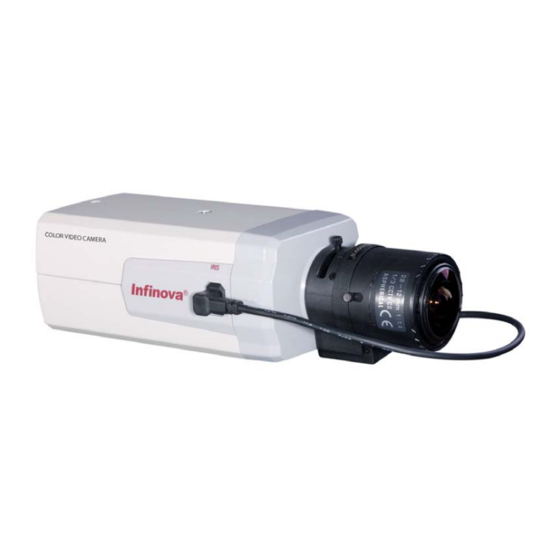
1. DESCRIPTION Thank you very much for purchasing our product. Infinova’s V5121-A7 & V5122-A7 series high-performance cameras feature a high resolution 1/3" SONY Exview HAD II CCD sensor and advanced Effio-E . These cameras provide 700 TV lines of resolution, improved color rendering and digital noise reduction, which ensure excellent video under extremely difficult illumination conditions. -
Page 5: Handling Precautions
2D digital noise reduction Motion detection Privacy mask Compensation Highlight (HLC) IR alarm input Auto Electronic Shutter (AES), Auto Gain Control (AGC), Backlight Compensation (BLC), Flickerless Mode (F.L.), White Balance (ATW/MANUAL/INDOOR/OUTDOOR/ FLUORES/PUSHLOCK Back Focus adjustment 12VDC/24VAC power input, centralized power-supply mode 3. -
Page 6: Introduction Of Panel Parts
5. INTRODUCTION OF PANEL PARTS The front, bottom and side parts: ① Lens Mount To attach the lens. This is applicable to both C-mount lenses and CS-mount lenses (1/3"). ② IRIS Terminal This is connected to an automatic iris control lens. The pin arrangement is:... - Page 7 Pin No. VIDEO DRIVE DC DRIVE POWER IN DAMP IRIS IN DAMP + DRIVE + N.C. DRIVE - Note: The camera supports DC DRIVE or VIDEO DRIVE. The default setting is DC DRIVE. ③ Camera-mounting bracket ④ Locating hole Use this hole to work with camera locator. ⑤...
- Page 8 Back panel and control parts ⑨ Video Out To connect an external video monitor. ⑩ Alarm Port To connect an external alarm device. ⑪ RS485 Communication Connector To connect with RS485 bus or communication terminal. Be sure to connect the D+/D- terminal correctly. ⑫...
-
Page 9: Mounting The Camera
6. MOUNTING THE CAMERA When mounting the camera on fixer, pan/tilt, etc., use 1/4-20UNC screw and the camera-mounting screw hole located on the camera-mounting bracket. The camera-mounting bracket can be mounted on the top or at the bottom of the camera. -
Page 10: Operation Instruction
7. OPERATION INSTRUCTION Menu overview --CAMERA MENU-- --LENS MENU-- SYNC TYPE IRIS LARGE PHASE SPEED CAM TITLE --AUTO MENU-- RETURN CAMERA ID EXIT PROTOCOL PELCO D SHUT MODE PRI-IRIS BAUDRATE 2400 SHUT MAX RETURN SHUT MIN EXIT AGC MODE MEDIUM-M RETURN EXIT --EXPOSURE MENU--... -
Page 11: Camera Set
4. In a submenu, move the cursor (>) to RETURN and press the , buttons to return to the previous menu. In every menu, move the cursor (>) to EXIT and press the button to exit the menu. Note: 1. If “…” appears right behind an option, it means there is a submenu under this option. -
Page 12: Sync Selection
--CAMERA MENU-- SYNC PHASE CAM TITLE CAMERA ID PROTOCOL PELCO D BAUDRATE 2400 RETURN EXIT 7.1.1 SYNC SELECTION Function: Set the synchronization mode for the camera. Options: INT: Internal. LL: Line Lock. Default as: INT. By adjusting the vertical phase, the LL mode can reduce monitor sync interruption caused by multiple camera switching. -
Page 13: Camera Id
TITLE CLEAR: Clear the camera title. Select “YES” to clear the designated title. 7.1.4 CAMERA ID Function: Set the current ID related information. Options: 001~127 for INFINOVA protocol; 001~254 for PELCO-P/D protocol. Default as: 001. 7.1.5 PROTOCOL Function: Set camera protocol. Keyboard’s protocol should be identical with camera’s protocol. -
Page 14: Baud Rate
7.1.6 BAUD RATE Function: Set camera baud rate. Keyboard’s baud rate should be identical with camera’s baud rate. Options: 2400, 4800, 9600. Default as: 2400. 7.2 CAM-LENS SET 7.2.1 TYPE Function: Set camera’s lens drive mode. Options: DC, VIDEO. This setting should be the same as that of the adopted lens;... -
Page 15: Exposure Menu
7.3 EXPOSURE MENU This setting is mainly for AE, BACK LIGHT, DAY/NIGHT, FLK, ATR. Note: for V5121-A7 series & V5122-A7 series, the default of DAY/NIGHT is different. For V5121-A7 series, default as: DAY; for V5122-A7 series, default as: AUTO…... - Page 16 SHUT MODE: Set shutter mode. Options: PRI-IRIS, PRI-SHUT. It is recommended to select PRI-IRIS when the camera is in Indoor applications and PRI-SHUT for Outdoor applications. If it set to PRI-IRIS, shutter speed will be 1/60s (NTSC) or 1/50s (PAL). At this point, the video brightness is up to iris size.
-
Page 17: Back Light
FIXED SHUT: Set the shut time. Options: PAL: 1/50-CRS, 1/120-FL, 1/250, 1/500, 1/1000, 1/2000, 1/10000, 1/100000. NTSC: 1/60-CRS, 1/100-FL, 1/250, 1/500, 1/1000, 1/2000, 1/10000, 1/100000. Options: -6dB, 0, 06dB, 12dB, 18dB, 36dB. AGC GAIN: 7.3.2 BACK LIGHT Function: Set backlight compensation. Options: OFF, , BLC. -
Page 18: Day/Night
Function: Switchover B/W and Color mode; predefine the threshold illumination values from B/W mode to Color mode and from Color mode to B/W mode; predefine the lag time for different modes switchover. Options: DAY, . For V5121-A7 series, default as: DAY; NIGHT… AUTO… for V5122-A7 series, default as: AUTO…... - Page 19 : Auto switch B/W and Color mode. Camera can automatically … AUTO switch from Color mode to B/W mode or from B/W mode to Color mode. Press the button to access its submenu. BURST CUT: B/W image without color synchronization burst; ON means B/W image with color synchronization burst.
-
Page 20: Flk
: B/W mode. Video is locked at B/W mode at this moment. Press the … NIGHT button to access its submenu. The BURST CUT setting refers to the instruction in AUTO mode. 7.3.4 FLK Function: Set Flickerless Function. When NTSC camera works in 50Hz power environment or PAL camera works in 60Hz power environment, activating the FLK function can prevent video from flicker. -
Page 21: Picture Adjust
COMPRESS: Set brightness modulating level. Options: LOW, MEDIUM, HIGH. Default as: LOW. ENHANCE: Improve image contrast. Options: LOW, MEDIUM, HIGH. Default as: LOW. 7.4 PICTURE ADJUST This menu is mainly for MIRROR, BRIGHT, CONTRAST, SHARP, HUE, C-GAIN, NR and MONITOR. 7.4.1 MIRROR Function: Current image mirror Options: ON, OFF. -
Page 22: Sharp
Options: 01~32. Default as: 17. 7.4.4 SHARP Function: Adjust image sharpness. Options: 01~32. Default as: 10. Image frame turns out to be sharper as the level goes up. 7.4.5 HUE Function: Adjust image hue. Options: 01~32. Default as: 17. 7.4.6 C-GAIN Function: Adjust color gain. -
Page 23: Monitor
MODE: Set noise reduction mode. Options: Y, C, Y/C. Y represents luminance signal; C represents chrominance signal. Y LEVEL: Y signal noise reduction level. Options: 01~08. Default as: 06. C LEVEL: C signal noise reduction level. Options: 01~08. Default as: 04. 7.4.8 MONITOR Function: Set Gamma value. -
Page 24: White Balance
7.5 WHITE BALANCE With WB MODE set to MANUAL --WB MENU-- --WB MENU-- WB MODE ATW... WB MODE MANUAL RED GAIN : RED GAIN : BLUE GAIN : BLUE GAIN : RETURN RETURN Function: Select white balance mode to compensate color temperature, rendering the true color of object. -
Page 25: Assist Function
OUTDOOR: Outdoor White Balance mode. This suits for outdoor environment with approximate 5500~6500K color temperature. INDOOR: Indoor White Balance mode. This suits for indoor environment with approximate 2600~3200K color temperature. FLUORES: Fluorescent lamp mode. This mode suits for fluorescent lamp environment with approximate 2000K color temperature. -
Page 26: Alarm
7.6.1 ALARM Function: Set alarm output mode. Options: OFF, EXT-IN, MD-OUT. Default as: OFF. EXT-IN: In EXT-IN mode, alarm signal is effective only if it is low level (TTL level). The image turns black when triggering alarm. It usually works with IR illuminators. -
Page 27: Privacy
--MOTION MENU-- AREA ENABLE LEFT RIGHT BOTTOM SENSE RETURN EXIT AREA: Select motion detection areas, up to 4 areas can be set. ENABLE: Enable or disable motion detection areas display. Options: ON, OFF. If it is set to ON, motion detection areas will display in the menu. The area size and sensitivity can be configured. -
Page 28: Lum Negative
AREA: Select privacy masks, up to 4 masks can be set. ENABLE: Enable or disable privacy masks display. Options: ON, OFF. If it is set to ON, privacy masks will display in the menu. The mask size can be configured. Note: Two coordinates (LEFT, TOP), (RIGHT, BOTTOM) determine a mask. -
Page 29: Blemish
7.7 BLEMISH Function: Configure blemish correction mode. DBC: Dynamic compensation mode. Options: ON, OFF. If it is set to ON, the camera will continuously compensate the blemish. DBC MODE is used to set the sensitivity of dynamic compensation. Options: STANDARD, H-SENSE, L-SENSE. SBC: Static compensation mode. -
Page 30: Appendix I Specifications
APPENDIX I SPECIFICATIONS Model V5121-A7 Series V5122-A7 Series Image Sensor 1/3" SONY Exview HAD II CCD Video Type NTSC/PAL (H) × 494(V), 480K; NTSC: 976 Effective Pixels (H) × 582(V), 570K PAL: 976 Scanning System 2:1 interlace Resolution 700TVL Day/Night... - Page 31 Motion Detection 4 programmable areas Picture Adjustment Mirror, Bright, Contrast, Sharp, Hue, C-Gain Noise Reduction Alarm Available, EXT-IN/ MD-OUT/ OFF RS485 Protocols: PELCO-P/D, INFINOVA; Remote Control Baud Rate: 2400/4800/9600bps Sync. System Internal/Line Lock 12VDC/ 24VAC Power Supply Power 4W (maximum)
-
Page 32: Appendix Ii Cable Diameter Calculation And
APPENDIX II CABLE DIAMETER CALCULATION AND LIGHTNING & SURGE PROTECTION Relation between 24VAC Cable Diameter and Transmission Distance In general, the maximum allowable voltage loss rate is 10% for AC-powered devices. The table below shows the relationship between transmission power and maximum transmission distance under a certain specified cable diameter, on condition that the 24VAC voltage loss rate is below 10%. - Page 33 Lightning & Surge Protection The product adopts multi-level anti-lightning and anti-surge technology integrated with gas discharge tube, power resistor and TVS tube. The powerful lightning and surge protection barrier effectively avoids product damage caused by various pulse signals with power below 4kV, including instantaneous lightning, surge and static.
- Page 34 Infinova 51 Stouts Lane, Monmouth Junction, NJ 08852, U.S.A. Tel: 1-888-685-2002 (USA only) 1-732-355-9100 Fax: 1-732-355-9101 sales@infinova.com V1.4 1401...
Need help?
Do you have a question about the V5121-A7 Series and is the answer not in the manual?
Questions and answers