Table of Contents
Advertisement
GAUI
Hobby
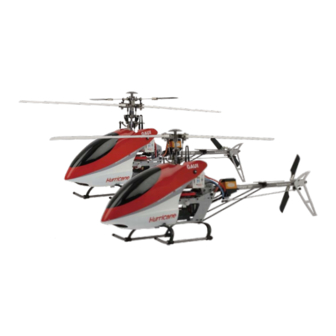
Hurricane EP200 V2 Series Instruction Manual
Equipment Recommendations :
1. Transmitter : 6 Channel or more ( CCPM-Capable )
2. Receiver : Micro Receiver 6 Channel or more ( NO : 921601 ~ 3 )
3. Servos : BMS 306BB 6g Servos ( NO : 922601 ) or 9g Servos as the
same size for EP400 class heli
4. Motor : 7.4V ~ 11.1V BL-Motor KV-4800 ( NO : 203501 )
5. Battery : Li-Po 7.4V ~ 11.1V 800mah ( NO : 926080、926081 )
6. ESC : 18A Micro ESC ( NO : 923182 )
7. Gyro : GU210 Heading Hold Gyro ( NO : 924210 ) for Hurricane200V2 SE
or GU365 FES 3-Axis Gyro ( NO : 924365 ) for Hurricane200V2 FES
8. Main Blades : SP Blades or Wooden Blades ( NO : 203308、203306 )
9. Flying Weight : 300g
10 % ( Depending on Equipment Used )
Advertisement
Table of Contents

Subscribe to Our Youtube Channel
Related Manuals for GAUI Hurricane EP200 V2 Series


Summary of Contents for GAUI Hurricane EP200 V2 Series
- Page 1 GAUI Hobby Hurricane EP200 V2 Series Instruction Manual Equipment Recommendations : 1. Transmitter : 6 Channel or more ( CCPM-Capable ) 2. Receiver : Micro Receiver 6 Channel or more ( NO : 921601 ~ 3 ) 3. Servos : BMS 306BB 6g Servos ( NO : 922601 ) or 9g Servos as the same size for EP400 class heli 4.
-
Page 2: Table Of Contents
Electronics installation and wiring Tail servo and the heading hold gyro setup Servo and Linkage Installation Pitch settings Head speed and pitch settings Main Rotor Head Assembling Main Fram Assembling Double Joints Tail Slider & CNC Tail Gear Case Assembling Belt Driven Unit Assembling 11-12 Shaft Driven Unit Assembling... -
Page 3: Electronics Installation And Wiring
Electronics Installation and Wiring Servo Servo (ELE) (PIT) Servo (AIL) CCPM (Swash plate) Servo (AIL) Tail Servo Servo Servo Heading Hold (PIT) (ELE) Gyro ( GU-210 ) Receiver Battery Heading Hold Gyro ( GU-210 ) Charging Battery plug Motor Tail Servo plug into Gyro ( S ) Gyro... -
Page 4: Tail Servo And The Heading Hold Gyro Setup
Tail servo and the heading hold gyro setup 1. Install the Gyro and the tail servo. 2. Connect the tail pushrod to the servo. Make sure the servo arm is 90 degrees to the tail pushrod. The ball link should be set at the second hole on the servo arm (as shown on left). -
Page 5: Servo And Linkage Installation
Servo and Linkage Installation Slide the swashplate up or down until Rotate each blade clockwise until the blades are parallel to the flybar (Left the blades are parellel to the flybar. View). The collective pitch angle is zero (Top View) at this position. -
Page 6: Pitch Settings
Pitch Setting (maximum) + 15 degrees 0 degrees - 15 degrees (maximum) Pitch : +13 Pitch : 0 Distance S (11.5mm) (swashplate height) Pitch : -13 (2.5mm) Head speed and pitch settings 1. Total collective pitch range should be approx 30 degrees ( -15 ~ +15 ). Normal flight should be about +12 to -5 degrees. -
Page 7: Head Speed And Pitch Settings
Head speed and pitch settings Equipment : BL Motor kv / 4800 15T Pinion gear SP Blades Li-Po Battery 7.4V / 800mah / 15C Flying Weight : 295 g Normal Mode Suggested Flight Time with 7.4v / 800 mah battery : 5 ~ 6 Min. Throttle Stick position Pitch... -
Page 8: Main Rotor Head Assembling
Main Rotor Head Assembling - 1 IMPORTANT: Make sure to use the non-locktite adhesive or similar material to adhere the screws while assemble the parts. #203625 W1.4X2.5X0.4 B1.5X4X1.3 M1.4X4 P1.5X7.7 P1.2X13.5 W2X3.5X0.5 PW3X3.7X1.6 O ring #203849 M2X8.4 M2X2 M1.4X5 W1.4X2.5X0.4 B1.5X4X1.3 B2X5X2.5 M1.4X6... -
Page 9: Main Rotor Head Assembling
Main Rotor Head Assembling - 2 IMPORTANT: Make sure to use the non-locktite adhesive or similar material to adhere the screws while assemble the parts. B1.5X4X1.2 #203591 M1.4X5 ① ② W1.4X2.5X0.4 ③ P1.4X2X3 Ø1.4X6 M1.4X5 M1.4X15 P1.4X2X9 M1.4X6 B8X12X2.5... - Page 10 Main Frame Assembling - 1 IMPORTANT: Make sure to use the non-locktite adhesive or similar material to adhere the screws while assemble the parts. (Use the locktite adhesive to adhere B3X6X2 both bearings to bearing mounts.) P2X3.5X12 M2X4.6 M2X8.4 Ø1.4X4 P2X3X3.5 M2X3.2 Fig.1...
- Page 11 Main Frame Assembling - 2 IMPORTANT: Make sure to use the non-locktite adhesive or similar material to adhere the screws while assemble the parts. B3X6X2 #203636 M2X3.2 P2X3.5X12 M2X14 P2X3.5X8.5 M2X3.2 3.5X3.5X31 #203209 Ø1.4X3 M1.4X6 #203311...
- Page 12 Double Joints Tail Slider & CNC Tail Gear Case Assembling Upper tail pitch lever P1.2X3.5 P2X2.5X3 B3X6X2 M2X8 P2X3X7.7 W3X4.6X0.5 N2X4 M1.4X5 #203135 M1.4X4 #203596 P1.4X1.7X2 M1.4X6 Do not tighten the screws too tight and make sure to use the B1.4X4X1.2 non-locktite adhesive to adhere the secres.(The CNC tail pitch...
-
Page 13: Belt Driven Unit Assembling
Belt Driven Unit Assembling-1 IMPORTANT: Make sure to use the non-locktite adhesive or similar material to adhere the screws while assemble the parts. Distance B = 4.5mm Use Locktite 609 , 680 , or similar material to adhere the long neck pinion gear to the motor shaft. -
Page 14: Belt Driven Unit Assembling
Belt Driven Unit Assembling-2 IMPORTANT: Make sure to use the non-locktite adhesive or similar material to adhere the screws while assemble the parts. Countsunk Washer M1.4X5 (front view) Make sure both sides of the belt are parallel in the tail boom, turn the front end of the belt 90 degrees counter - colckwise... -
Page 15: Shaft Driven Unit Assembling
Shaft Driven Unit Assembling-1 IMPORTANT: Make sure to use the non-locktite adhesive or similar material to adhere the screws while assemble the parts. 4.5mm Distance B = Use Locktite 609 , 680 , or similar material to adhere the long neck pinion gear to the motor shaft. -
Page 16: Shaft Driven Unit Assembling
Shaft Driven Unit Assembling-2 IMPORTANT: Make sure to use the non-locktite adhesive or similar material to adhere the screws while assemble the parts. W3X4.6X0.5 Ø1.4X4 B3X6X2.5 Ø1.4X4 M2X5 #203126 Insert the tail shaft assembly into the boom holder, install the crown gear onto the driven shaft , adjust the gear mesh and tighten the screws of the boom holder. -
Page 17: Esc Instruction
ESC instruction Product Functions Battery Management There is a built-in Battery Management function in the speed controller. The power cut off timing is based on the cell number and continuous current drains of the battery. There are two options defined in the battery management, one is for Li-Polymer batteries and another for using with NiMH battery. -
Page 18: Specifications Of Motor And Esc
Specifications of Motor and ESC Specifications of 18A ESC Working Voltages(Maximum) ------------ 5.5 V ~ 16.8 V(Maximum) Maximum Current(Instantaneous) ----------------------------- 24 A Continual Current ----------------------------------------------- 18 A Built-in BEC --------------------------------- Maximum Input 12.6 V Output 5 V / 2 A Low Battery Protect ------------------------------ 3.1V~2.9V / cell Temperature Overload ------------------------------------------ 120 Specifications of BL Motor... -
Page 19: Gu-365 Fes Gyro Installing
GU-365 FES Gyro installing 1.Cut the sponge tape into 4 small squares (8mm), attached them to the corners of name plate side. Gyro box must not have contact Wires must not Gyro must not be tied with heli except sponge tape be pulled tightly Use C/A to adhere frames and bottom... -
Page 20: Fes 2Blade Head & Swashplate Assembling
FES 2Blade Head & Swashplate Assembling W1.4X2.5X0.4 P1.4X2X3.1 M2X8.4 Ø1.4X6 M1.4X5 P2X3.5X2.5 B2X5X2.5 B1.5X4X1.2 M2X12 M1.4X6 Mast and Upper Swashplate Grips and Head Assembling Lock Assembling 0 Pitch degrees (Fig. 1) The ball link and the arm shod e perpendicular at 0 pitch degrees (Fig.2) M1.4X6 Install the linkages... -
Page 21: Optional & Replacement Parts
Optional & Replacement Parts 203308 203591 203306 861902 Main Rotor Blades Pack Tail Rotor Belt CNC Washout Base & Arms SP Main Rotor Blades(200L) (Wooden 200L) (for H200 Series) Assembly 203702 203560 203570 203580 CNC Main Grips set FES Upper Swashplate Lock Ass'y CNC Swashplate Assembly CNC Mixing Arms (for 100~250 class 3mm Mast) - Page 22 Optional & Replacement Parts 203718 203707 203710 203714 FES 2Blade System full conversion set FES 3Blade System full conversion set FES 4Blade System full conversion set FES 5Blade System full conversion set (for 100~250 class 3mm Mast) (for 100~250 class 3mm Mast) (for 100~250 class 3mm Mast) (for 100~250 class 3mm Mast) 203085...
- Page 23 Optional & Replacement Parts 203250 203151 203270 203271 Guide Wheel with Bearing Pack Bearings(1.4x4x1.2)x2pcs Bearings(1.4x4x2)x2pcs Flange Bearing(2x5x2.3)x2pcs 803725 203280 203290 203445 H200V2 Upper Frame Set Flange Bearing(3x6x2.5) Bearings(2x5x2.5)x3pcs Bearings(3x6x2.5)x2pcs (for 6g~9g Servo) 203446 203608 203616 203634 H200V2 Lower Frame Conver H200V2 Lower Frame Set CNC Mast Mount CF Fin &...
- Page 24 Optional & Replacement Parts 203191 203196 203197 203209 Titanium anodized Tail Booms Black CF Tail Boom Titanium anodized Tail Boom H200 Tail Boom Support Set Pack (for Belt version) with one bearing(Shaft version) (for Belt version) (Long) 203222 203223 203240 203532 H200 Rudder Linkage with H200 Alu Tail Driven Shaft...
- Page 25 Optional & Replacement Parts 203529 203311 203531 203572 Damper Rubbers Pack Mini Spacer & Brass Washer Tail Servo Mount Set Boom Support Pack (for canopy) Spare Pack 203167 204904 910011 203166 Blade Support H200 FRP Painted Canopy Decal(2) (for H100~H200) Light-weight Body-Canopy(9g) (B Type) 203165...
-
Page 26: Optional & Replacement Parts
Optional & Replacement Parts 921601 921602 921603 922601 Micro Receiver Micro Receiver Micro Receiver BMS 306BB Servo (SRX-6UH-40MHZ) (SRX-6UH-35MHZ) (SRX-6UH-72MHZ) 923182 924210 924365 926080 (GUEC GE-182)ESC 18A (GUEC GU-210) (GUEC GU-365) Flybarless (GUEC GB-080)Li-Po Battery E-Stabilizer (FES) (7.4v 800mah) with Connectors(For BL Motor) Heading Hold Gyro 926081 203503... -
Page 27: Specification Of Screws
Specification of Screws ( 1 : 1 ) 15.0 M1.4 Machine screws Ø Self taping screws 12.0 10.0 Ø2.0 Self taping screws M2.0 Tiny head machine screws 10.0 M2.0 Machine screw 14.0 12.0 10.0 M2.0 Socket head machine screws M2.0 Ø3 Ø2 Socket set screws...
Need help?
Do you have a question about the Hurricane EP200 V2 Series and is the answer not in the manual?
Questions and answers