Advertisement
Quick Links
Advertisement

Subscribe to Our Youtube Channel
Related Manuals for skyangel F-35


Summary of Contents for skyangel F-35
- Page 1 Assembly and Operating Manual...
-
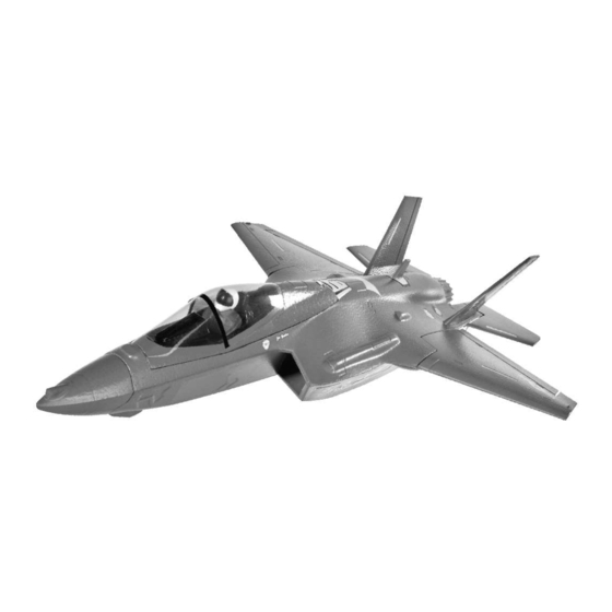
Page 2: Parts Illustration
2.4GHz radios systems from most reputable model retail shops. SKYANGEL Hummingbird range and thank you are recommended, similar to the unit included with for placing your trust in us. our deluxe version. - Page 3 Assembly and Operating manual Parts List Description Fuselage Nose Cone Wing Set – One Left (and one Right) Wing Panel Tail Set - One Left (and one Right) Horizontal Stabilizer with Elevator Tail Set - One Vertical Stabilizer Cockpit Canopy One Left (and one Right) Main Landing Gear Fixed Plate Two Main Wheels Front Wheel Fixed Plate...
- Page 4 Assembly and Operating manual Fig. 2 - Locate the fuselage and nose cone Fig. 3 - Glue the nose to the front of fuselage (glue Fig. 4 - Glue the horizontal stabilizers to the slots not included). at the rear of the fuselage (glue not included). Fig.
- Page 5 Assembly and Operating manual Fig. 9 - The photo shows the finished view after Fig. 10 - Locate the push rods set. Fig. 8 - Apply glue to the sides of each main wing gluing the wings in place. panel (glue not included). Fig.
- Page 6 Assembly and Operating manual Fig. 14 - Glue the vertical stabilizer sections as Fig. 15 - Connect the electronic speed controller Fig. 16 - Locate the battery and canopy. Charge shown in the photo (glue not included). and servos to the receiver. Refer to the radio the battery according to the safety instructions instructions for the correct channel sockets and before installing.
- Page 7 Assembly and Operating manual Fig. 20 - Locate the fixed plate for the front wheel. Fig. 21 - Glue the fixed plate into the fuselage as Fig. 22 - Attach the front wheel to the fixed plate. shown in the photo (glue not included). Fig.
- Page 8 Assembly and Operating manual Optional parts (not required) Fig. 26 - Painted missiles, for extra realism, are included. Fig. 27 - Missiles shown after being separated. Cut apart for assembly as shown Fig. 28 - Glue missiles into the main wing slots (glue not included). Fig.
- Page 9 Assembly and Operating manual Fig. 30 - Charge the flight battery; connect the Equalizer lead using and adapter lead matching your charger (adapter lead not included). Fig. 31 - Switch the transmitter on, and move the throttle stick to the “ Motor OFF”position. (Diagram MODE 1 right throttle control stick)
- Page 10 Assembly and Operating manual Fig. 32 and 33 - Checking Ailerons and Elevators - Check that the control surfaces respond to the appropriate movements of the transmitter sticks. If not, swap over the connectors at the receiver. - Check the neutral position of the control surfaces; you may need to screw the clevises in or out to correct any discrepancy.
- Page 11 Assembly and Operating manual Fig. 35 - Checking the model’ s balance - Place the flight battery in its compartment, without connecting. - Mark the Centre of Gravity (CG) on both sides of the fuselage; the position is shown in the photo. - Support the model at the marked points and allow it to hang freely.
- Page 12 For the first flight you should wait for a relatively calm day with no more than a gentle breeze. Jiangyin Skyangel Electronic Technology Co., Limited. 5th Floor, A3 Building, Xinjianxing Technology Industrial Park, Fengxin Road, Guangming Town, Bao'an, Shenzhen City, 518107 China...
Need help?
Do you have a question about the F-35 and is the answer not in the manual?
Questions and answers