
Related Manuals for skyangel Nano F15


Summary of Contents for skyangel Nano F15
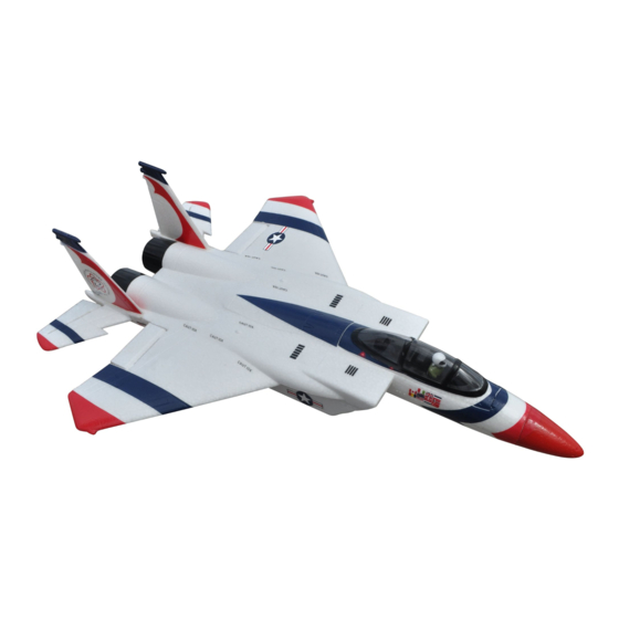
- Page 1 Assembly and Operating Manual Nano SPECIFICATION: Length: 21-3/5"(550mm) Wing Span: 15-3/5"(395mm) Flying Weight: 5-4/5oz。(165g.)
- Page 2 Assembly and Operating Manual Dear customer, by the glue manufacturer. Allow the glue to fully To fly the Nano F15 you will need a radio control cure (harden) to the point where the joint can be Congratulations on your choice of a system with at least four channels.
-
Page 3: Parts Illustration
Assembly and Operating Manual Fig. 1 Open the box and check all the parts. Parts Illustration Parts List Description Fuselage Nose Wing Set – One Left (and one Right) Wing Panel Tail Set - One Left (and one Right) Horizontal Stabilizer with Elevators Tail Set - Two Vertical Fin Cockpit Canopy... - Page 4 Assembly and Operating Manual Fig. 2 - Glue the control rod to Horizontal tail. (glue Fig. 3 - Remove any excess glue and hold in Fig. 4 - Reverse the procedure to the left side. The not included) position until glue sets. The photo shows the photo shows the finished view.
- Page 5 Assembly and Operating Manual Fig. 8 - Apply glue to the fuselage. Fig. 9 - Apply glue to the Vertical tail. Fig. 10 - Remove any excess glue and hold in position until glue sets. Fig. 11 - The photo shows the finished view. Fig.
- Page 6 Assembly and Operating Manual Fig. 14 - Apply glue to the fuselage Fig. 15 - Remove any excess glue and hold in Fig. 16 - The photo shows the finished view. position until glue sets. Fig. 17 - Reverse the procedure to the left Fig.
- Page 7 Assembly and Operating Manual Fig. 20 - Tighten the control rod with screw. Fig. 21 - The photo shows the finished view. Fig. 22 - Connect the wing panel push rod to the servo arm at third hole. Fig. 23 - Assemble the push rod to the wing panel Fig.
- Page 8 Assembly and Operating Manual Fig. 26 - Reverse the procedure to the right Fig. 27 – Apply glue to the missile. Fig. 28 – Apply glue to the wing panel. elevator push rod. The photo shows the finished view. © Fig.
- Page 9 Assembly and Operating Manual Fig. 32 - Hold in position until the glue sets , photo Fig. 33 - Reverse the procedure to the right Fig. 34 – Apply glue to the landing gear. shows the finished view. elevator push rod. The photo shows the finished view.
- Page 10 Assembly and Operating Manual Fig. 38: Apply glue to the nose cone (glue not Fig. 39: Apply glue to the fuselage (glue not Fig. 40: Assemble the nose cone to the fuselage, included). included). The photo shows the finished view. Fig.
- Page 11 Assembly and Operating Manual Fig. 44: canopy is held in place by magnets and Fig. 45: The photo shows the finished view. Fig.46: Congratulations, you have completed the can be lifted off. assembly process. We hope you enjoy flying your new model!
- Page 12 Assembly and Operating Manual Fig. 47 - Charge the flight battery; connect the Equalizer lead using and adapter lead matching your charger (adapter lead not included) Fig. 48- Switch the transmitter on, and move the throttle stick to the “Motor OFF” position. (Diagram MODE 1 right throttle control stick)
- Page 13 Assembly and Operating Manual Fig. 49 and 50- Checking Ailerons and Elevators Check that the control surfaces respond to the appropriate movements of the transmitter sticks. If not, swap over the connectors at the receiver. Make sure do not apply glue to control rods fastener before check the neutral position of the control surfaces Stand behind the model.
- Page 14 Assembly and Operating Manual Fig. 52- Checking the model’s balance Place the flight battery in its compartment, without connecting. Mark the Centre of Gravity (CG) on both sides of the fuselage; the position is shown in the photo. Support the model at the marked points and allow it to hang freely.
- Page 15 Switch the motor on, and launch the airplane strongly into the wind, with the fuselage and wings level. Allow the Nano F15 Jet to fly straight and level initially, do not try to turn it when it is close to the ground.
- Page 16 Jiangyin Skyangel Electronic Technology Co., Limited. 5th Floor, A3 Building, Xinjianxing Technology Industrial Park, Fengxin Road, Guangming Town, Bao'an, Shenzhen City, 518107 China Phone: +86 755 33699201 Fax: +86 755 33699203 www.skyangelrc.com...
Need help?
Do you have a question about the Nano F15 and is the answer not in the manual?
Questions and answers