KMC Controls FlexStat series Operation Manual
Bacnet programmable thermostats
Hide thumbs
Also See for FlexStat series:
- Application manual (60 pages) ,
- Operation manual (46 pages) ,
- Quick reference manual (2 pages)
Table of Contents
Advertisement
Operation Guide
Contents
Overview ................................................................ 3
Applications and Installation ................................... 3
Operation (Basic) .................................................... 4
Navigation .......................................................... 4
Room Temp. Setpoint Adjustment ....................... 4
H/C, Fan, Occupancy, and Override ................... 4
Main Menu and Settings ...................................... 4
Display Options .................................................. 5
Configuration (Setup) .............................................. 6
Main Menu Overview ......................................... 6
About the FlexStat ............................................... 6
Advanced Menu .................................................. 7
Damper Setup ............................................. 7
Humidity Setup ........................................... 8
Motion Sensor Setup ................................... 8
Optimum Start Setup .................................. 9
Sensor Setup ................................................ 9
Setback (OAT) Lockout Setup .................... 10
Staging Setup ............................................. 10
Valve Setup ............................................... 10
(Advanced) CB (Control Basic) Programs ....... 10
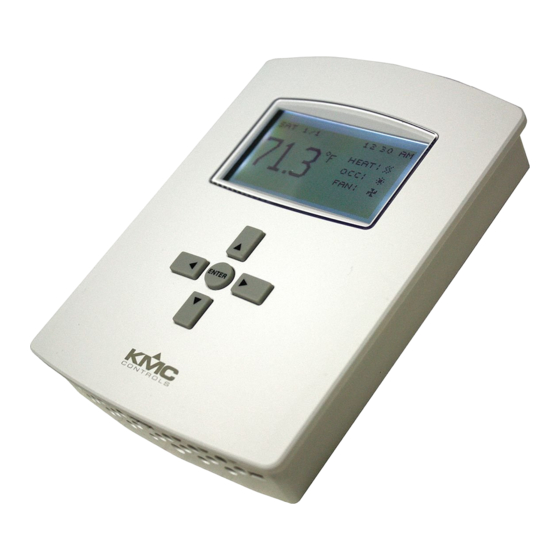
FlexStat
BACnet Programmable Thermostats
Specifications, design, and operation are subject to change without notice.
1
Sensor (and DCV) ................ 11
2
Sensor Setup and Information ........... 11
2
Sensor Calibration ............................. 11
2
(Advanced) Communications (BACnet) .......... 16
(Advanced) Date/Time ................................... 16
(Advanced) BACnet Device Properties ........... 17
(Advanced) Inputs .......................................... 17
(Advanced) Temp. Setpoint Limits .................. 18
(Advanced) PID Loop Configuration .............. 18
(Advanced) Restart/Restore ........................... 18
(Advanced) Test .............................................. 20
(Advanced) Trend Logs ................................... 20
(Advanced) User Interface (UI) ...................... 21
Display Blanking ....................................... 21
Inactivity ................................................... 21
Rotation Values .......................................... 21
Show Temperature Tenths (Decimals) ........ 21
Mode ......................................................... 21
Alarms ............................................................... 23
Date/Time ......................................................... 23
DCV (Demand Control Ventilation) .................. 24
Schedules .......................................................... 24
FlexStat
™
Operation Guide, Rev. M
Advertisement
Table of Contents
Troubleshooting

Subscribe to Our Youtube Channel
Related Manuals for KMC Controls FlexStat series


Summary of Contents for KMC Controls FlexStat series
-
Page 1: Table Of Contents
FlexStat ™ BACnet Programmable Thermostats Operation Guide Contents (Advanced) CO Sensor (and DCV) ....11 Overview ..............3 Sensor Setup and Information ... 11 Applications and Installation ........3 Sensor Calibration ......11 Operation (Basic) ............ 4 DCV (Demand Control Ventilation) Setup . 12 Navigation ............ - Page 2 Setpoints ............25 Input, Sensor, and Value Issues ......33 System Modes ........... 25 Level Value Is Frozen or Is 0 ....33 Trend Viewer ............. 26 and DCV Sequences Are Not Working ..33 Level Is “Too High” ......... 34 Resetting the FlexStat ..........
-
Page 3: Overview
Overview Applications and Installation The award-winning KMC FlexStat series of intelli- Communication with Other BACnet gent temperature/humidity/occupancy-sensing, wall- Network Devices and Remote Monitoring mounted, thermostat/controllers are native BACnet Advanced Application Controllers (B-AAC) for use in a BACnet system. The FlexStat simplifies net- worked zone control for common packaged HVAC Optional equipment, such as packaged rooftop units, fan coil Humidity, Temperature units, heat pumps, and other similar applications. In Motion, Sensing and CO addition, applications such as pressure dependent Sensing VAV, terminal reheat, and medium-sized central Applications station air handling equipment applications may • AHU also be addressed through the on-board libraries of • FCU Up to 6 Ana- Up to 9 programs built into the devices. -
Page 4: Operation (Basic)
Operation (Basic) Configuration Screens Home Screen MAIN MENU WED 9/3 5:43 PM ABOUT ADVANCED COOL: ALARM OCC: Up (Setpoint) DATE/TIME FAN: SCHEDULE SETPOINTS HUM: 31%RH SYSTEM ADVANCED Right Left Override Screens APPLICATION CB PROGRAMS SYSTEM MODE COMMUNICATION (Menu) (Override) SYSTEM ENABLE: AUTO DATE/TIME DEVICE... -
Page 5: Display Options
Display Options WED 11/19 3:20 PM WED 11/19 3:22 PM WED 11/19 3:20 PM WED 11/19 3:20 PM COOL: COOL: COOL: COOL: OCC: OCC: OCC: OCC: FAN: FAN: FAN: FAN: HUM: 36% RH HUM: 37% RH HUM: 36% RH OUTSIDE: 56° F Fahrenheit decimal values are not displayed by de- By default, rotation values in the lower right of the fault but can be enabled in the User Interface menu. -
Page 6: Configuration (Setup)
Configuration (Setup) NOTE: Menus shown in this document reflect About the FlexStat FIRMWARE VERSION R2.0.0.21 or later. Actual context-sensitive screens are ABOUT FLEXSTAT dependent on firmware version, FlexStat MODEL: BAC–141136CE MORE ABOUT model, and options selected. FW: FLEXSTAT R1.3.0.0 COMMUNICATION APP: AIR HANDLER FIRMWARE NOTE: If appear at the top of the screen OPT: MOD H / MOD C HARDWARE (such as in the Main Menu), scroll up or MORE UPTIME: 28D 00:32:57 down to see the rest of the menu’s off- screen choices. -
Page 7: Advanced Menu
Advanced Menu Auxiliary Heat (Heat Pump Only) Setup AUX HEAT SETUP ADVANCED AUX HEAT: COMP LOCKOUT APPLICATION DELAY (MINS): 60 CB PROGRAMS COMP OAT LOW: 40° F COMMUNICATION DATE/TIME DEVICE INPUTS LIMITS For HPUs, auxiliary heat can be set for none, with The Advanced Menu displays various submenus. compressor lockout, or without compressor lockout. Not all submenus can be seen on the screen at one time. Scroll up or down to see additional submenus. The Delay time controls how long the space temper- ature must be below the auxiliary heat’s start tem- NOTE: The Advanced Menu has more submenus perature before auxiliary heat will turn on. (For more than can appear on the screen at once. Keep details, see the Auxiliary/Emergency Heat section... -
Page 8: Humidity Setup
When BAC-1xxxxx models have an application with Motion Sensor Setup the CO sensor AND the modulating economizer MOTION SENSOR option enabled, menu items for DCV (Demand OCC OVERRIDE: ENABLE Control Ventilation) will appear. For information STATE: OCCUPIED about the DCV options, see (Advanced) CO2 Sensor STANDBY: DISABLE (and DCV) on page —OFFSET: 3° F —TIMER (MINS): 30 Fan Setup FAN SETUP SPEEDS: CONSTANT SPEED A motion/occupancy sensor may be enabled (the OFF DELAY (SECS): 180 default) to trigger occupancy override (enabled by UNOCC: AUTO default, but only functional during scheduled off... -
Page 9: Optimum Start Setup
reverting from Standby back to Occupied Sensor Setup mode (although it may still take some SENSOR SETUP time for the room to reach its normal IN 2: DISCH AIR TEMP temperature). See (Advanced) CO2 Sensor IN 9: CO2 (and DCV) on page SPACE TEMP: REMOTE NOTE: DCV is only available in models with the -- IN 1 IS ONBOARD -- IN 7 IS REMOTE built-in CO sensor. Scheduled Scheduled On Time Off Time... -
Page 10: Setback (Oat) Lockout Setup
(Advanced) CB (Control Basic) Programs Setback (OAT) Lockout Setup SETBACK LOCKOUT CB PROGRAMS OAT LOCKOUT: ENABLE PROG1: RUNNING PROGRAM #1 LOCKOUT TEMP: 30° F PROG2: RUNNING SETPOINTS & MODES PROG3: RUNNING AUTO-RUN: TRUE PROG4: RUNNING CHANGE: READY PROG5: RUNNING STATE: RUNNING PROG6: HALTED HALT REASON: NORMAL PROG7: IDLE... -
Page 11: (Advanced) Co Sensor (And Dcv)
reference value and this reference value is the lowest (Advanced) CO Sensor (and DCV) concentration to which the sensor is exposed. ABC CO2 SENSOR Logic requires continuous operation of the sensor for SENSOR INFO periods of at least 24 hours. CALIBRATION The BAC-14xxxx models (with T6615 model sen- sors) have a calibration option for applying gas CO2 SENSOR INFO MODEL: T6615 to the sensor for maintaining maximum accuracy. SUB VOL: A15 CO2 CALIBRATION The BAC-14xxxx has a dual channel sensor (a CO SW DATE: 090217 ELEVATION: 0 channel measures gas concentration, and a reference S/N: AB00011759 REFERENCE GAS: 300 channel measures the sensor signal intensity). Self- CO2: 873 MODE: MONITOR ELEVATION: 0... -
Page 12: Dcv (Demand Control Ventilation) Setup
NOTE: Although the caps are not required for NOTE: After initiating, the calibration process maintaining the accuracy of the sensor, takes approximately 4 minutes and cannot they protect against insects, dust, or other be stopped by any button presses until contaminants from getting inside the tubes. the cycle is complete. If power is removed If a cap is lost, the sensor will still function before the calibration process is completed, normally, but the cap should still be the old values will be retained. replaced as soon as is feasible. NOTE: No matter what the normal inactivity time- out setting is, time-out for the calibration 7. Connect the tubing from the reference gas cylin- screen is 10 minutes. See (Advanced) User der to either of the FlexStat calibration tube fit- Interface (UI) on page tings using the 3.5"-long adapter tubing (201-403- 03) from the HTO-1103 FlexStat Firmware Flash 12. After the calibration process is complete, Mode Upgrade Kit. One end of the adapter tubing fits will change from Calibrate to Monitor. Press the over one of the FlexStat calibration tube fittings. Left button and information about the most recent The other end fits inside the standard 1/4" OD calibration (date, elevation, and ppm of reference tubing that comes from the regulator. gas) will be displayed in the lower part of the screen. 13. Turn off the gas, remove the connected tubing, Calibration Gas Cylinder... - Page 13 Although BAC-12xxxx FlexStats do not have a built- 100% Basic DCV Configuration in CO sensor, they still have DCV control sequences available. When DCV is enabled in the Damper Setup menu of these models, IN9 is assumed to be Outside Air connected to an external SAE-10xx CO (duct or DCV Signal Damper Component space) sensor. 0–5 VDC on that input (configured Position to OAD Component in the (Advanced) Inputs menu) will map to 0–2000 ppm. The output of the connected SAE-10xx must also be configured to match the FlexStat’s input (see the installation guide for the appropriate SAE-10xx model), and the FlexStat’s IN9 pull-up resistor must Base Setpoint Maximum be set for 0–12 VDC (see the appropriate FlexStat Space CO installation guide)! BAC-13xxxx/14xxxx FlexStats also have the external sensor option, and if used, the • STANDARD DCV—When the BAC-13xxxx highest of the two readings (internal vs. external) settings are properly configured, this complies will be used to control DCV sequences. The CO ppm with CA Title 24, Section 121(c). This would also...
- Page 14 CO2 BASE (PPM) = The presumed average CO 100% Advanced DCV Configuration concentration level of outside air at the OA Max building’s location (400 ppm default). OA Full DCV DAMPER SETUP = A test mode is used to Outside Air determine proper outside air damper DCV Signal Damper Component position values for OA AREA, OA FULL, Position to OAD* OA MAX, and OA PURGE. The required Component *Under Normal airflows for these four positions are Vent Mode operation OA Area determined by ASHRAE 62.1-2007 section (see Vent Mode description) 6.2.6.2. A technician/balancer uses this menu to set specific damper positions and Base Maximum measure the resulting airflows. The damper...
- Page 15 OA MAX = The maximum allowable % of outside • Standby—After the motion sensor has air damper position (40% default) for not detected motion for 30 minutes, ventilation (not cooling) purposes. The temperature setpoints are adjusted value is determined using DCV DAMPER (down for heating and up for cooling), SETUP. and the outside air damper is closed. OA PURGE = During the 60 minutes prior to • Recovery—After a period in which scheduled start time, the outside air the supply fan was off, the space is damper will open to this position (0% ventilated with an increased percentage default) to perform a purge of the zone. of outside air (to compensate for the The value is determined using DCV previous reduced ventilation). DAMPER SETUP. • Override—Ventilation override has been manually selected from the DCV (Unoccupied) (Occupied) (Unoccupied) menu, and the space is temporarily (30 minutes default) driven to the full Scheduled Scheduled On Time Off Time ventilation position (for maximum Occupancy Occupancy design occupancy) if it is not already Standby* Override*...
-
Page 16: (Advanced) Communications (Bacnet)
Max Info Frames (view only) is the maximum (Advanced) Communications (BACnet) number of information frames (data packets) that COMMUNICATIONS a controller may send out before it must pass the ACTIVE: CONFIGURE token. ETHERNET SETTINGS IP SETTINGS To communicate with a KMD-5576 through the data COMMUNICATIONS FOREIGN DEV SETTINGS port at the bottom of the case, IP/Ethernet-enabled ACTIVE: ETHERNET MS/TP SETTINGS FlexStat models in one of the Ethernet or IP modes MAC: 00:D0:6F:89:00:01 must (temporarily) be set for MS/TP mode (and COMMUNICATIONS restarted)! (See Resetting the FlexStat on page 26.) ACTIVE: IP ADDRESS: 192.168.1.254 For IP and IP Foreign Device communications, SUBNET MASK: 255.255.0.0 consult with the system administrator for the COMMUNICATIONS... -
Page 17: (Advanced) Bacnet Device Properties
(Advanced) BACnet Device Properties powered-up FlexStats during non-DST periods (e.g., most of November through DEVICE INSTANCE: February). If the time has erroneously NAME: FlexStat_101 advanced one hour after an initial time LOCATION: KMC Controls synch command, the easiest solution is to simply send a second time synch command. This will correct the device time. Alternately, the hour can be changed in the FlexStat’s menu. To set the BACnet device instance, name, and If the FlexStat is used in a BACnet network with UTC location, press: (Coordinated Universal Time) synchronization (via 1. Up/Down to move among entries. broadcasting or addressing a single thermostat) set the UTC Offset value. The UTC Offset value is in minutes 2. Enter to select. and corresponds to the distance of the local time zone NOTE: In firmware versions R1.3.0.4 and earlier, to the zero degree meridian. In stand-alone operation the FlexStat could also be restarted or or networks that do not have UTC broadcasts, setting restored to factory defaults from this this value is not necessary. menu. In R2.0.x, this function was moved to... -
Page 18: (Advanced) Temp. Setpoint Limits
(Advanced) Temp. Setpoint Limits (Advanced) PID Loop Configuration LIMITS LOOP CONFIGURATION 66° F 2.0° F OCC MIN CLG: COOL PROP: OCC MAX HTG: 80° F HEAT PROP: 2.0° F UNOCC MIN CLG: 66° F COOL INTG: 4/hr UNOCC MAX HTG: 80° F HEAT INTG: 4/hr MIN SETPT DIFF: 2°... -
Page 19: (Advanced) Security Levels And Passwords
NOTE: When setting a password, the Up button (Advanced) Security Levels and Passwords increases the alphanumeric value (0 SECURITY through 9 and then A through Z). The ACCESS LEVELS Down button decreases the value. DO NOT PASSWORDS FORGET THE ADMIN PASSWORD! ACCESS LEVELS PASSWORDS The required password level is specified in the SETPOINT ADJ: NONE USER: 1 0 0 0 prompt. MAIN MENU: ADMIN OPERATOR: 1 2 3 4 SYSTEM MODE: OPER ADMIN: 5 6 7 8 To lock the buttons after configuration is complete OCC OVERRIDE: USER... -
Page 20: (Advanced) Test
log monitors AV78, which gives the highest of the (Advanced) Test two readings.) See also Damper Setup on page TEST 7, (Advanced) CO2 Sensor (and DCV) on page 11, LCD/KEY TEST Setpoints on page 25, and DCV (Demand Control Ventilation) on page 24. Other options that can be user-configured for trend logs include the following: • The humidity sensor is AI5 but is mapped to AV22 for display purposes. The test menu merely tests the display’s pixels and key functions. • When AI4 is configured for OAT, OAT is mapped to AV23 for display purposes. • The motion sensor is BI6. However, BI6 is ac- (Advanced) Trend Logs tive only when motion is detected by the sensor. -
Page 21: (Advanced) User Interface (Ui)
(Advanced) User Interface (UI) Show Temperature Tenths (Decimals) With R2.0.0.13 and later firmware, Fahrenheit tem- USER INTERFACE perature values on the display change in whole DISPLAY BLANKING: degree increments by default, and Celsius values INACTIVITY (SECS): 60 USER INTERFACE ROTATION VALUES change in 0.5° increments. Changing the default No INACTIVITY (SECS): 60 SHOW TEMP TENTHS: NO to Yes will show tenths of a degree values for both ROTATION VALUES MODE: STANDARD SHOW TEMP TENTHS: NO scales. MODE: HOSPITALITY This does not affect setpoint adjustments, which are HOSPITALITY OPTIONS... - Page 22 • Single Setpoint will keep the setpoint at what- scheduled occupied and unoccupied ever the user has last selected (except when a periods. For example, if a user changes motion sensor optionally puts the FlexStat in the occupied cooling setpoint to 76°, the standby mode—see Motion Sensor Setup on page occupied cooling setpoint will remain at 76° 8). The FlexStat will stay On (in occupied mode), on subsequent days until a user adjusts it and the schedule will be ignored. again. The same is true for the unoccupied setpoint. To automatically reset setpoints • To use the Schedule option, the schedule must to default values at particular times, a be configured before entering Hospitality mode. building automation system can overwrite (See Schedules on page 24.) If no schedule is config- the setpoint value objects or custom ured by the user, the default schedule is always programming can be put into the FlexStat. On (occupied). See the FlexStat Application Guide. (Hospitality Mode Sample Screens) Custom Hospitality mode programming is required for: WED 10/01 3:20 PM • Use of Field C for displaying messages.
-
Page 23: Alarms
• CO Alarm—carbon dioxide level is higher than Alarms 1,050 ppm (or lower than 300 ppm, indicating a sensor error) for more than 450 seconds. This is SAT 4/11 3:20 PM ALARMS available only in FlexStats with a CO sensor and * SPACE TEMP ALARM 04/11 COOL: the DCV option enabled in the Damper setup. OCC: 04/11/09 08:37:56 See Damper Setup on page 7 and (Advanced) CO2 FAN: <AI1> SPACETEMP Sensor (and DCV) on page 11. (The monitored ob- PRESENT VALUE = 90.1 HUM: 20%RH SERVICE EXCEEDS HIGH_LIMIT... -
Page 24: Dcv (Demand Control Ventilation)
DCV (Demand Control Ventilation) Schedules DEMAND CONTROL VENT SCHEDULE VENT OVERRIDE: ENTIRE WEEK [MON–SUN] VENT MODE: STARTUP WEEKDAYS [MON–FRI] ENTIRE WEEK WEEKEND [SAT–SUN] 7:30:00 AM ON INDIVIDUAL DAYS 2: 5:15:00 PM OFF HOLIDAYS This menu appears under the Main Menu only if [—>] DELETES ENTRY DCV Advanced Setup is selected. For more options and information, see (Advanced) CO2 Sensor (and To select the desired schedule, press: DCV) on page 11 and Damper Setup on page 1. Up/Down to move among entries. -
Page 25: Setpoints
will be erased. (Special day schedules will System Modes then need to be added again through the INDIVIDUAL DAYS menu). SYSTEM SYSTEM ENABLE: AUTO OCC OVRIDE (HRS): 1.0 HOLIDAYS HOL1: JAN 1 2009 HOL2: MAR 21 2009 HOL3: MAY 26 2009 HOL4: JULY 4 2009 HOL5: SEPT 1 2009 HOL6: NOV 27 2009 This menu allows changes to system enable (auto, HOL7: NOV 28 2009 off, heat, or cool modes) and occupancy override The Holiday entries will override the normal time. -
Page 26: Trend Viewer
Trend Viewer Resetting the FlexStat Types of Reset TREND VIEWER SPACE TEMP 2: SPACE HUMIDITY If the FlexStat is not operating correctly or if a low 3: FAN limit alarm has occurred, the FlexStat should be 4: COOL 1 reset (reinitialized). Any reset interrupts normal op- 5: COOL 2 eration, and three types of reset exist: TL #1 SPACE TEMP • A warm start is generally the least disruptive op- APR11 1:27PM, 70.3 tion (restarting normal operation the quickest). APR11 2:27PM, 71.3 APR11 3:27PM, 71.6 • If problems still persist, try a cold start. (This APR11 4:27PM, 71.8... -
Page 27: Restore Factory
A cold start does the following in the FlexStat: Restore Factory • (After zeroing out objects during the restart Restore Factory (restoring the FlexStat to the factory process) returns all object values to their relin- settings) does the following: quished defaults (until they are updated by the • Clears present values. FlexStat’s programs). • Restores the object database/configuration to the • Restarts the controller’s Control Basic programs. defaults. • Leaves configuration and programming intact. • Restarts the controller’s (factory installed) Con- NOTE: Menu changes may take up to about two trol Basic programs. minutes to write to nonvolatile Flash NOTE: The MAC address and device instance are memory. If power to the FlexStat is lost not restored to their original defaults, and during this time, changes may be lost. custom Control Basic programs are not Restarting the FlexStat from its menu, deleted. If custom Control Basic programs are TotalControl, or BACstage are the installed, all factory programs are restarted recommended methods. but all custom Control Basic programs are NOTE: When power is restored after an outage, halted. Custom programs may be restarted by the FlexStat will attempt to do a warm loading/running the programs from the CB start as long as the values in RAM are... -
Page 28: Network Connection
Network Connection MS/TP Network Communication PC Data Port Connection Connect the EIA-485 MS/TP network wiring and set The FlexStat is equipped with a PC data port located the EOL switches accordingly. (See the Installation at the bottom of the thermostat housing. This port Guide for wiring and end-of-line switch informa- provides a temporary EIA-485 (formerly RS-485) tion.) connection to the digital network for network setup or troubleshooting. From the FlexStat menus, adjust the device instance number, the MAC address, and baud rate from the To connect a computer to the port, a means of defaults as necessary. Set the Max Master to the converting the EIA-485 signal to a USB or EIA-232 minimum necessary for the network. See (Advanced) (formerly RS-232) signal will be needed. For USB, BACnet Device Properties on page 17 and (Advanced) use a KMC KMD-5576 USB Communicator. For Communications (BACnet) on page 16.) EIA-232, use a third-party interface. (See the instruc- tions included with those devices and software.) To NOTE: The current FlexStat MAC address and connect to the PC data port: device instance numbers can be viewed in the About menu. Each BACnet device on a... -
Page 29: Maintenance
Maintenance Accessories Remove dust as necessary from the holes in the top Mounting and bottom. Clean the display with a soft, damp HMO-10000 Horizontal or 4 cloth and mild soap. x 4 handy box To maintain maximum sensitivity of an optional wall mounting built-in motion sensor, occasionally wipe dust or dirt plate for BAC- off the lens—but do not use any fluid on the sensor. 10xxx/12xxxx models only, light almond (shown) HMO-10000W HMO-10000 in Firmware Upgrade white The existing version of firmware can be viewed from the About the FlexStat screen. (See About the Flex- SP-001 Screwdriver Stat on page (KMC branded) with flat blade Firmware in the FlexStat can be upgraded using a PC (for terminals) and an HTO-1103 Firmware Flash Upgrade Kit avail- and hex end (for able from KMC Controls. (For full upgrade instruc- cover screws) tions, see the HTO-1103 Installation Guide.) (The old KMD-5699 part number was changed to HTO-1103 Network Communications and Firmware... -
Page 30: Troubleshooting
Troubleshooting Alarm Issues Back-Up Issues NOTE: Backing up the existing settings and Alarm, (False) Fan Fail firmware image before or during the • Check configuration. Be sure the Fan Status upgrade process (using the Firmware option is not selected when there is no sensor/ Upgrade Tool, TotalControl, or BACstage) switch for it. is recommended practice. • Check that the IN2 (fan status) input pull-up • See the documentation for the program used to resistor switches are fully latched in the correct back-up the FlexStat. positions. Any passive, dry contact should use • See service bulletin SB1111A Back-up and the 10K Ohm setting. (See the Connections and Restore Issues, concerning unconfigured event Wiring section of the relevant FlexStat Installa- enrollment objects and checksum errors on NIC tion Guide.) cards. • Check IN2 (fan status) input wiring. • For HTO-1103 FlexStat Firmware Upgrade Kits • Check the connected fan status sensor/switch. received prior to Feb. 7, 2012 that have Rev. D (on the silver label) of the programming pod, see • Using BACstage or TotalControl, check that AI2... -
Page 31: Communication Issues
Using a power screwdriver on these nicate through the data port at the bottom of the screws is not recommended. Also, use only the cover. See (Advanced) Communications (BACnet) mounting screws supplied by KMC Controls since on page 16 and Resetting the FlexStat on page other types of screws may damage the FlexStat. • Upgrade to the latest version of BACstage (ver. -
Page 32: Display Is Blank (Or Erratic)
Display Is Blank (or Erratic) Display Keeps Resetting • If the display comes on when a button is pushed, • Carefully remove the FlexStat cover from the Display Blanking is enabled. (See (Advanced) backplate, check pins and connectors, and rein- User Interface (UI) on page 21.) sert. (See Cover Binds on Backplate on page 31.) • Check for a tripped circuit breaker to the trans- • Check for proper supply voltage from the former. transformer and that the transformer has enough capacity (VA) for all connected devices (see their • Carefully remove the FlexStat cover from the respective data sheets). backplate. (See Cover Binds on Backplate on page 31.) Check pins and connectors. Ensure the NOTE: Wiring must be adequate to avoid... -
Page 33: Custom Programming And Web Issues
Custom Programming and Web Issues Input, Sensor, and Value Issues Control Basic Programs Do Not Work Level Value Is Frozen or Is 0 • After power is first applied or the FlexStat is NOTE: The FlexStat has a library of built- restarted, the sensor goes through a warm-up for in applications and options that are approximately half a minute. During the time the configured through the FlexStat’s display. sensor count will be 0 ppm. See (Advanced) CO2 Beyond these standard configurations, Sensor (and DCV) on page custom changes can be added to a FlexStat using KMC’s BACstage (ver. 2.4.0.26 or • The BAC-14xxxx models self-calibrates approxi- later) or TotalControl (ver. 2.0.5 or later). -
Page 34: Co Level Is "Too High
Level Is “Too High” Motion/Occupancy Sensor Does Not Work • See the CO and DCV Sequences Are Not Work- • The initial firmware (R.1.0.0.0 and earlier) did not ing section above. support this sensor within the built-in selectable programs. Custom programming was required— • To reduce nuisance complaints by occupants, see the FlexStat Application Guide. Upgrade to turn off the visibility of the CO level rotation in the latest firmware for built-in support. the display. See (Advanced) User Interface (UI) on page • After an initial power-up or restart, the motion/ occupancy sensor requires about 30 seconds DCV Menu Is Not Visible before it will begin responding to motion. • In the BAC-12xxxx/13xxxx/14xxxx models, DCV • The motion/occupancy sensor initiates override Setup is visible only when an application with a only during “off” times in the schedule. See... -
Page 35: Temperature Setpoint Is Not Maintained
• Check that the thermistor (on models without Time and/or Date Are Not Correct humidity sensors) is centered in its hole at the NOTE: When a FlexStat is powered up after bottom of the case and has an air gap around it. losing the RTC (Real Time Clock) time, it Also check that its leads are not pinched, shorted, will revert to the default time and date of or broken and that the tape holding down the January 1, 2000, 12:00:00 AM. leads is not loose. (Some early models with • Set time and date in the menu. See Date/Time on humidity sensors did not have the additional page 23 and/or (Advanced) Date/Time on page thermistor—temperature was derived from the • Using BACstage or TotalControl, send a time same chip that measured humidity.) synchronization command. • Using BACstage or TotalControl, check that AI1 (space temp.) is not configured as “Out Of NOTE: An issue can occur if a FlexStat has been un- Service.” powered long enough for it to lose its RTC timekeeping during the period DST (Day- • Check that the FlexStat is NOT mounted on an light Saving Time) is in effect (currently exterior wall, mounted on or near a large thermal... -
Page 36: Output, Fan, And Relay Issues
Output, Fan, and Relay Issues Analog Output Does Not Work Fan Does Not Run NOTE: The animated fan icon is coupled with CAUTION BV18 in the packaged programming (not Do not mistakenly connect 24 VAC to an analog the actual fan output terminal). output ground. This is not the same as a relay’s • Select Occupied mode from the Home Menu— switched common. -
Page 37: Relay (Internal) Does Not Work
Upgrading Firmware Issues NOTE: See also the HTO-1103 (KMD-5699) Relay (Internal) Does Not Work FlexStat Firmware Flash Upgrade Kit Installation Guide, for more information. CAUTION (The KMD-5699 product number was Relays are for Class-2 voltages (24 VAC) only. changed to HTO-1103 in August 2010.) Do not connect line voltage to the relays! CAUTION NOTE: Max. output current is 1 A for individual relays @ 24 VAC/VDC or a total of 1.5 A To prevent damaging the FlexStat or programming per bank of 3 relays (relays 1–3, 4–6, and pod, be sure all the pins align properly with the 7–9). Do not attach a device that draws... -
Page 38: Flexstat Malfunctions After Upgrade
• If the USB port does not appear in the drop- FlexStat Malfunctions After Upgrade down list, close the tool, remove power to the • After the update process is over, if the FlexStat FlexStat, disconnect the FlexStat from the USB display remains blank but the backlight is on or port, reconnect the FlexStat to the USB port, the display locks up at a later time, check that restore power to the FlexStat, and restart the tool. the WD jumper is reinstalled on the CORRECT • For any communication error (such as an “Op- pins. (See the illustration on the previous page.) eration has failed!” message) check all connec- • Check the application configuration. tions and restart the Firmware Upgrade Tool. If the HTO-1103 kit was received prior to Feb. NOTE: Restoring to the factory defaults and 7, 2012 and has Rev. D on the silver label of the reconfiguring might be needed if how the programming pod, see the FlexStat Programming FlexStat operates changes. Read all notes Pod Jumper Position Service Bulletin SB0212A to accompanying the firmware update! check for the correct jumper position within the NOTE: If custom Control Basic programs are pod. installed and set to autorun, whenever the • For display/interface issues in the Firmware firmware is updated, ALL (factory and Upgrade Tool, right-click in the firmware panel custom) programs are halted. If custom (on the right) and select Restore Defaults. -
Page 39: Wiring Issues
Wiring Issues Installation Wiring Considerations Troubleshooting Wiring Problems • Review the wiring information in the relevant CAUTION FlexStat installation guide. To avoid damage from ground loops and other • Remove the FlexStat from the backplate and communication issues in networked FlexStats, inspect the terminals for loose or shorted wires. correct phasing on network and power connections on ALL the networked controllers • Use a voltmeter and ohmmeter to check the is critically important. -
Page 40: Support
Support Important Notices The KMC logo and TotalControl are registered FlexStats come with a printed trademarks and BACstage is a trademark of KMC Installation Guide. Addi- Controls, Inc. All rights reserved. No part of this tional resources for configura- publication may be reproduced, transmitted, tran- tion, application, operation, scribed, stored in a retrieval system, or translated programming, upgrading into any language in any form by any means without and much more is avail- the written permission of KMC Controls, Inc. able on the award-winning KMC Controls web site The material in this document is for information (www.kmccontrols.com). purposes only. The contents and the product it de- scribes are subject to change without notice. KMC The collection of FlexStat Controls, Inc. makes no representations or warran- documents won a prestigous ties with respect to this document. In no event shall publications award for techni- KMC Controls, Inc. be liable for any damages, direct cal marketing support from or incidental, arising out of or related to the use of the Chicago chapter of the this document. Society for Technical Commu- nication in March 2010. FlexStat Operation Guide, Rev. M... -
Page 41: Reference
Reference Acronyms and Abbreviations Common acronyms and abbreviations in FlexStat IP = Internet protocol and related documents include: LCD = liquid crystal display amp = amperes mA = milliamperes A = amperes MAC = media access control AAC = Advanced Application Controller MAT = mixed air temperature A/C = air conditioning max. = maximum AC = alternating current min. = minimum AHU = air handling unit mm = millimeters AI = analog input MS/TP = master-slave/token-passing avg. = average NC = normally closed AWG = American Wire Gauge NO = normally open BACnet = Building Automation Control network OAT = outside air temperature BTL = BACnet Testing Laboratories pF = picofarad C = Celsius RA = reverse acting cfh = cubic feet per hour RH = relative humidity cfm = cubic feet per minute RS = Recommended Standard cm = centimeters RTC = real time clock DA = direct acting RTU = roof top unit DAT = discharge air temperature SPDT = single pole double throw DC = direct current... -
Page 42: Definitions Of Terms
Definitions of Terms master devices can initiate requests for data but slave devices cannot (since slaves can only reply For definitions of various terms in this to messages from other devices). KMC advanced document, refer to the award-winning application controllers are all MS/TP master pocket-sized Green Building and Con- devices. trols Glossary (SB-046). A hyperlinked online version can be downloaded from Native BACnet Device—A device that is fully BACnet the Brochures section of KMC Controls compatible and uses BACnet as its primary, if not web site, www.kmccontrols.com. Some exclusive, method of communication. of the more important glossary terms for this document are included on this page: PID (Proportional Integral Derivative) Control—A control algorithm that enhances the PI control Air Handling Unit (AHU)—An HVAC system compo- algorithm by adding a component that is pro- nent that conditions and delivers air through the portional to the rate of change (derivative) of the system. It typically contains one or more supply deviation of the controlled variable. This com- and return fans, heating/cooling coils, and filters pensates for system dynamics and allows faster to condition the air. control response. -
Page 43: Index
Index Symbols Build Date: 6 BV4 (Low Limit Condition): 23 4 x 4 Handy Box Mounting Plate: 29 BV5 (Fan Fail Alarm): 23 Abbreviations: 41 Calibration About the FlexStat: 6 Analog Input Offset: 17 Access Levels, Password: 19 CO2 Sensor (Gas): 11 Accessories: 29 Temperature Offset: 17 Acronyms: 41 CA Title 24: 13 Adapter CO2 Sensor: 11, 21, 33 Backplate, HTO-1103: 11, 29 Cold Start: 26 Tubing, CO2 Calibration: 12 Communication Adjustment. See Configuration; Override; Setpoint MS/TP, Ethernet, and IP: 16 Administrator Password: 19 Settings: 16 Advanced Menu: 7 Troubleshooting: 16, 31 AI1 (Temp. Sensor): 9, 20, 23 Compressor Lockout: 7 AI2 (DAT or FST): 9, 20, 23 Conductors: 39 AI3 (MAT): 23 Conduit: 39 AI4 (OAT): 10, 20 Configuration (Setup): 6 AI5 (Humidity Sensor): 20, 23 Control Basic Programs: 10, 27, 33 AI7 (Remote Temp. Sensor): 9, 23 COOL AI9 (Remote CO2 Sensor): 9, 20, 23 INTG (Integral): 18 AI10 (CO2 Sensor): 20, 23... - Page 44 Device Heat, Cool, Auto, Off (System Enable): 25 Instance: 6, 17, 27, 28 Heating Fan: 8 Properties: 17 Heat Pump Unit (HPU): 42 Discharge Air Temperature (DAT): 9, 20 HMO-10000 Mounting Plate: 29 Display Home (Temperature Display) Screen: 4 Blanking: 5, 21, 32 Horizontal Handy Box Mounting Plate: 29 Decimal Values (Tenths): 5, 21 Hospitality Mode: 21 Hospitality Mode: 5, 21 HPU (Heat Pump Unit): 7 Locked: 5, 21 HTO-1103 FlexStat Firmware Flash Upgrade Kit: 11, Options: 5 Humidity Rotation Values: 5, 21 Alarm: 23 Temperature Scale: 5, 7 Dehumidification Setpoint: 25 Time-Out: 21 Setup: 8 Troubleshooting: 32 Trend Log: 20 Economizer (Damper): 7, 13 IN2 (Fan Status or DAT): 9 EIA-485: 28, 42 IN7 (Remote Temp. Sensor): 9 Elevation Correction/Setting: 11, 12 Inactivity Time-Out: 21 EOL (End Of Line) Switches: 31 Initial Setup: 6 Ethernet: 16, 28, 31 Inputs: 17 External Sensor. See Remote Installation: 3 IP: 16, 28, 31 Factory Defaults: 17, 26 Jumper, WD: 32, 37...
- Page 45 MAC Address: 6, 16, 27, 28 Parts (Accessories): 29 Main Menu: 4, 6 Passwords: 19, 25 Maintenance: 29 PC (Network) Data Port: 28 MAT. See Mixed Air Temperature (MAT) PECI (Portland Energy Conservation, Inc.): 8, 13 Max Master: 16, 28, 31 Phasing, Network and Power: 39 Menu PID (Proportional Integral Derivative) Loop: 18, 42 Advanced: 7 Pod, Programming (HTO-1103): 38 Main: 6 Portland Energy Conservation, Inc. (PECI): 8, 13 Minimum Setpoint Differential: 18 Port, PC Data (Network) Connection: 28 Mixed Air Temperature (MAT): 23 Power Outage/Removal: 27 Model Number: 6 Pre-Purge Ventilation Mode: 15 Modes Programming System: 4, 25 Custom: 10, 29, 33 User Interface: 21 Pod, HTO-1103: 38 Ventilation: 15 Proportional Control: 42 Modulating Economizer: 7, 13 PROP (Proportional Band): 18 Motion Detector. See Motion Sensor Protocol: 42 Motion Sensor: 8, 20, 34 Pull-Up Resistor Switches: 30, 34 MS/TP: 16, 28, 31, 42 Purge: 15 Multistage H/C: 10 Real Time Clock (RTC): 42 Native BACnet Device: 42 Recovery Ventilation Mode: 15 Navigation: 4...
- Page 46 Trend Logs Motion: 8 Inputs: 9, 11, 20 Remote Temperature: 9, 17 Intervals: 20 Setup: 9 Setup: 20 Troubleshooting: 33 Viewer: 26 Type: 17 Troubleshooting: 30 Value: 17 Tubing, CO2 Calibration Adapter: 12 Serial Number: 6 Setback Lockout: 10 Setpoints UI4, Rotation Value: 21 Adjustment: 4, 25 Unit Ventilator: 42 Menu: 25 Universal Time, Coordinated (UTC): 17 Temperature (Only): 4 Update Manager: 10, 38 Troubleshooting: 35 Upgrading Firmware: 29, 37 Setup and Configuration: 6 USB Communicator: 28 SP-001 Screwdriver: 29 USB (Universal Serial Bus): 42 Space User Interface Modes: 21 Humidity Alarm: 23 User Password: 19 Temp Alarm: 23 UTC. See Universal Time, Coordinated (UTC) Temperature Trend Log: 20 Span, Cool and Heat: 25 Staging: 10 Value, Sensor: 17 Standby, Occupancy: 8, 15 Valve Setup: 10 Start (Reset), Cold or Warm: 26 Ventilation. See Demand Control Ventilation (DCV)
Need help?
Do you have a question about the FlexStat series and is the answer not in the manual?
Questions and answers