Advertisement
Quick Links
Mounting
3.25
83
A
in.
mm
5.16
116
B
in.
mm
0.88
22
C
in.
mm
0.38
10
D
in.
mm
2.58
66
E
in.
mm
3.25
83
F
in.
mm
Rough-in Preparation
For optimum temperature sensor performance, the
thermostat must be mounted on an interior wall
and away from heat sources, sunlight, windows,
air vents, and air circulation obstructions (e.g.,
curtains, furniture).
Complete rough-in wiring prior to installation:
• Route the cable from the thermostat location to
the actuator to which it will connect. See Wiring
on page
2.
• If needed, install the HMO-1161 mounting
backplate. See Additional Information on page
Mounting the Thermostat
1. If the thermostat is
locked on the backplate,
turn the two hex screws
(in the two outermost
holes) in the backplate
CLOCKWISE until they (just) clear the cover.
Swing the thermostat up and away from the
backplate to remove it.
CAUTION
To prevent damage to the board, do not insert
a screwdriver into any holes other than the two
outermost holes. To prevent mounting screw heads
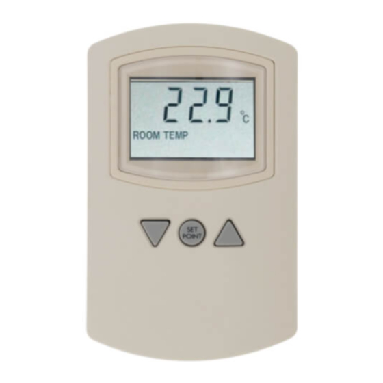
CTE-5201
Installation and Operation Guide
A
Electronic Room Thermostat (Modular)
C
D
RJ-12
Modular
Connector
Pin 6
B
Pin 1
Pin 1 and 6
N/C
*0 VDC during Unoccupied Off mode when temperature stays
above 50° F
from touching the circuit board in the thermostat, use
only the mounting screws supplied by KMC Controls.
Using other screws may damage the thermostat. Do
not turn screws in farther than necessary to remove
the cover.
2. Route the cable through the backplate.
3. With the hex screws toward the
4.
floor, fasten the backplate to the
outlet box with the supplied screws.
(The backplate mounts directly on
vertical 2 x 4 inch boxes, but re-
quires an HMO-1161 wall mounting
plate for horizontal or 4 x 4 boxes.)
4. Insert the modular end of the cable
into the jack of the thermostat.
5. Place the top of the thermostat over the top of
the mounting base and swing it down over the
hex screw brackets. Be careful not to pinch the
wiring.
6. Back the hex screws out of the backplate brackets
(counterclockwise) until they engage the ther-
mostat and hold it in place.
1
Pin 2 and 5
Pin 3
Common
Supply
(14–19 VDC)
Installation and Operation Guide
CTE-5201
E F
Pin 4
Output
(2–10 VDC)*
Advertisement

Subscribe to Our Youtube Channel
Related Manuals for KMC Controls CTE-5201


Summary of Contents for KMC Controls CTE-5201
-
Page 1: Mounting The Thermostat
(e.g., curtains, furniture). from touching the circuit board in the thermostat, use only the mounting screws supplied by KMC Controls. Complete rough-in wiring prior to installation: Using other screws may damage the thermostat. Do • Route the cable from the thermostat location to not turn screws in farther than necessary to remove the actuator to which it will connect. See Wiring... - Page 2 12 feet HSO-2220 20 feet HSO-2250 50 feet HSO-5010 3-Way “Y” Modular Connector Wires: Orange & Orange Stripe CTE-5201-16 Analog Electronic Thermostat HSO-2250 Thermostat Cable, 50-foot (typical) Wires: Green & Green Stripe Up to 6 MEP-4x42s XEE-6xxx-xxx HSO-2121 HSO-2212 on each side Transformer Cable...
- Page 3 3 for details. Up/Down buttons) until the display begins to flash. Toggle Between °F and °C Room temperature, setpoint, proportional band, deadband, and offset will thereafter be displayed in To temporarily view the other temperature scale, flip the desired units. See also Toggle Between °F and °C open the cover (hinged on the left side), and momen- on page tarily press the F/C button. The alternative scale will appear as long as the backlight is on. UNOCC To make the desired F or C scale mode permanent Momentarily pressing this button will put the unit (the scale persists instead of being momentary), press into the Unoccupied mode (Unoc). It will stay in and hold the F/C button down for approximately 10 this mode until either the Setpoint or Up/Down seconds until the display begins to flash. To return to buttons are pushed. There are two unoccupied mode the previous scale mode, repeat the process. options, Off (the default) or Deadband: • In Off Mode (OFF), the output voltage is forced to 0 VDC (0%). If the room temperature falls CTE-5201 3 Installation and Operation Guide...
-
Page 4: Additional Information
F, Min. of 20%, and Max. of 100%) in Deadband mild soap. Each component is designed for depend- Mode, while the room temperature is between 60 able, long-term reliability, and performance. Careful and 80°, the output remains at 60%. installation will also ensure long-term reliability and performance. NOTE: Using Deadband Mode would usually keep the unoccupied room temperature closer to the default (occupied) setpoint temperature Additional Information than the Off Mode. For specifications, a complete list of accessories, and PROP other information, see the CTE-5201-16 Data Sheet. The proportional band (Pb) is the temperature band around the setpoint over which the output will vary from MIN to MAX due to the proportional action alone. The proportional band is adjustable from 2 to 6° F (1.1 to 3.3° C). As long as there is an error between room tempera- ture and setpoint, the integral action (In) will cause the output to integrate up or down. The integral time is the time it takes the integral action to repeat the effect of the proportional action. The integral time is For more information about the sample application adjustable from 15 to 30 minutes. Setting the integral with MEP-4x42 actuators, see the MEP-4x42 Installa- time to 0 will disable the integral action. tion Guide and Data Sheet.
Need help?
Do you have a question about the CTE-5201 and is the answer not in the manual?
Questions and answers