Table of Contents
Advertisement
Quick Links
Installation
A
B
SET
POINT
A
B
3.25 in.
5.16 in.
0.88 in.
83 mm
116 mm
22 mm
NOTE: For specifications and other information,
see the
CTE-5202 Data
NOTE: For detailed applications, cross-references,
accessories, and other information, see the
CTE-5202 Applications
Rough-in Preparation
For optimum temperature sensor performance, the
thermostat must be mounted on an interior wall
and away from heat sources, sunlight, windows,
air vents, and air circulation obstructions (e.g.,
curtains, furniture).
If replacing an existing thermostat, label wires as
needed for reference when removing the existing
thermostat.
Complete rough-in wiring at each location prior to
thermostat installation. Cable insulation must meet
local building codes.
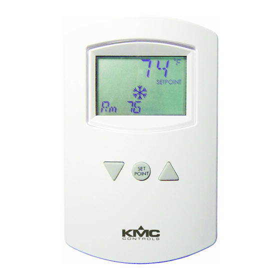
CTE-5202 Electronic Room Thermostat with LCD Display
Installation and Operation Guide
C
E
C
D
3.25 in.
0.15 in. diameter
83 mm
3.81 mm diameter
Sheet.
Guide.
Electronic Room Thermostat with LCD Display
Mounting and Wiring
The thermostat must NOT be:
• Mounted on an exterior wall.
• Mounted on or near a large thermal mass (e.g.,
concrete block wall).
D
• Blocked from normal air circulation by obstruc-
tions.
• Exposed to heat sources (e.g., lights, computers,
copiers, or coffee makers) or to sunlight (at any
time of the day).
• Exposed to drafts from windows, diffusers, or
E
returns.
• Exposed to air flow through the conduit (from
leaks in plenum ducts)—put plumber's putty or
similar material inside the conduit to block air
flow.
1. If the thermostat is locked on the backplate, turn
the two hex screws (in the two outermost holes)
in the backplate CLOCKWISE until they (just)
clear the cover. Swing the thermostat up and
away from the backplate to remove it.
CAUTION
To prevent damage to the board, do not insert
a screwdriver into any holes other than the two
outermost holes. To prevent mounting screw heads
from touching the circuit board in the thermostat, use
only the mounting screws supplied by KMC Controls.
Using other screws may damage the thermostat. Do
not turn screws in farther than necessary to remove
the cover.
2. Route the cable through the backplate.
1
CTE-5202
Installation and Operation Guide
Advertisement
Table of Contents

Related Manuals for KMC Controls CTE-5202


Summary of Contents for KMC Controls CTE-5202
-
Page 1: Mounting And Wiring
To prevent mounting screw heads needed for reference when removing the existing from touching the circuit board in the thermostat, use thermostat. only the mounting screws supplied by KMC Controls. Using other screws may damage the thermostat. Do Complete rough-in wiring at each location prior to not turn screws in farther than necessary to remove thermostat installation. Cable insulation must meet... - Page 2 (If no Auxiliary Flow is desired, set AO1 AUX to 0.) NOTE: For examples of applications, including To change any of the system or advanced features, replacing a CTE-510x with the CTE-5202, press the Up or Down button until the desired (flash- see the CSP-5001/5002 Applications Guide. ing) ADVANCE or SYSTEM menu appears and then press the Setpoint button. CTE-5202 Electronic Room Thermostat with LCD Display Installation and Operation Guide...
- Page 3 The SYSTEM menu enables changing: NOTE: For additional details of sequence op- • Sequence (SEQ1, SEQ2, or SEQ3)—see erations, see the CTE-5202 Applications Sequences charts Guide. • °F (ENGLISH) or °C (METRIC) NOTE: AO1 is typically used to control the cool- • BLANK—Display blanking (NO or YES)— ing output (primary air damper or cooling when blanked, the temperature will display for valve), and AO2 is used to control the heat- no more than 30 seconds after a button is pushed ing output (VAV reheat or heating valve). CTE-5202 Electronic Room Thermostat with LCD Display Installation and Operation Guide...
-
Page 4: Important Notices
REE-50xx Electric relay modules for stag- KMC Controls, Inc. makes no representations or ing, fan control, and reheat warranties with respect to this document. In no event STE-140x Duct temperature (Type III) sen- shall KMC Controls, Inc. be liable for any damages, sors direct or incidental, arising out of or related to the use of this document. STE-1454/1455 Strap-on temperature (Type III) sensors KMC Controls, Inc. 19476 Industrial Drive New Paris, IN 46553 574.831.5250 www.kmccontrols.com info@kmccontrols.com CTE-5202 Electronic Room Thermostat with LCD Display © 2013 KMC Controls, Inc. Installation and Operation Guide 821-019-02B...
Need help?
Do you have a question about the CTE-5202 and is the answer not in the manual?
Questions and answers
CAN i hâve information for And l’Oder thermostat manuel around 2011
The manual information for the KMC Controls CTE-5202 thermostat includes details on installation, specifications, applications, troubleshooting, and accessories. The CTE-5202 Installation Guide provides general mounting and connection details, including power and input/output connections. The CTE-5202 Data Sheet contains specifications and other information. The CTE-5202 Applications Guide covers detailed applications, cross-references, troubleshooting, and accessories. The thermostat features an LCD display, supports hot/cold air changeover using a Type III thermistor sensor, and includes an unoccupied/standby setback function. Maintenance instructions recommend cleaning dust from ventilation holes and wiping the display with a soft, damp cloth and mild soap.
This answer is automatically generated