Table of Contents
Advertisement
Quick Links
Download this manual
See also:
User Manual
Advertisement
Table of Contents

Related Manuals for Rosslare AuraSys L-4


Summary of Contents for Rosslare AuraSys L-4
- Page 1 ™ AuraSys 4-/8-Zone Alarm Panel Hardware Installation Manual Models: L-4K L-4PCBA...
- Page 2 ROSSLARE. ROSSLARE reserves the right to revise and change this document at any time, without being obliged to announce such revisions or changes beforehand or after the fact.
-
Page 3: Table Of Contents
Table of Contents Table of Contents 1. Introduction ............... 9 2. Technical Specifications and Features ......13 3. Installation and Wiring ..........16 Installation Quick Guide ..............16 Installation Prerequisites ..............16 3.2.1 Preparing the Installation Environment ............16 3.2.2 Preparing the Wiring ................. - Page 4 Table of Contents 5.2.2 Installer Level ..................... 41 5.2.3 User ......................42 Entering Programming Mode (Installer/Master) ........42 Enable Installer Code Access ............. 42 Installer Programming Level .............. 42 5.5.1 Entering Parameters .................. 43 5.5.2 General Procedural Steps ................43 5.5.3 Programming Tables ..................
- Page 5 Table of Contents B. Reporting Codes .............. 67 C. Battery Load Capacity ............ 69 D. Programming Worksheets ..........70 Customer Information............... 70 Installer Information ................70 Device Information ................70 Zone Worksheet ................71 E. Declaration of Conformity ..........72 F.
- Page 6 Figure 2: Rosslare L-4K Panel ................ 10 Figure 3: Rosslare L-4 PCBA Panel ..............11 Figure 4: Rosslare L-4C, L-4CL, and L-4CU Panels ......... 11 Figure 5: Rosslare L-4D, L-4DL, and L-4DU Panels ......... 12 Figure 6: L-4 PCBA Panel Mounting Holes............. 17 Figure 7: L-4C Mounting Template ...............
- Page 7 List of Tables List of Tables Table 1: Hardwiring Schematics for Single Zone System ........ 32 Table 2: Hardwiring Schematics for Doubled Zone System ......32 Table 3: Resistor Color Scheme ..............34 Table 4: Resistors Provided ................34 Table 5: User Function Buttons ..............37 Table 6: Operational Indicators ..............
- Page 8 ROSSLARE exclusive warranty and liability is limited to the warranty and liability statement provided in an appendix at the end of this document. This manual describes the maximum configuration of the system with the ...
-
Page 9: Introduction
Introduction Introduction The AuraSys™ L-4 4/8-zone Security System family is a compact and advanced 4-zone (doubled) hardwired control panel for residential and light commercial intrusion alarms. There are several versions of the L-4 product: L-4 – Arm Away, Arm Home, and Disarm using key switch ... -
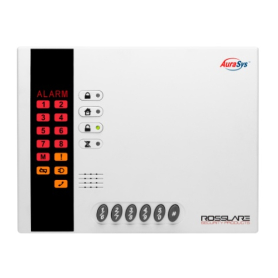
Page 10: Figure 1: Rosslare L-4 Panel
Introduction Figure 1: Rosslare L-4 Panel Figure 2: Rosslare L-4K Panel AuraSys™ L-4 Family Installation Manual... -
Page 11: Figure 3: Rosslare L-4 Pcba Panel
Introduction Figure 3: Rosslare L-4 PCBA Panel Figure 4: Rosslare L-4C, L-4CL, and L-4CU Panels AuraSys™ L-4 Family Installation Manual... -
Page 12: Figure 5: Rosslare L-4D, L-4Dl, And L-4Du Panels
Introduction Figure 5: Rosslare L-4D, L-4DL, and L-4DU Panels AuraSys™ L-4 Family Installation Manual... -
Page 13: Technical Specifications And Features
Technical Specifications and Features The AuraSys L-4 family supports a wide range of security features. This section lists the specifications for the features that comprise the security system, as well as the electrical and mechanical specifications of the Security System. - Page 14 Technical Specifications and Features Electrical Characteristics Power Supply Type Linear type (recommended) Input Voltage L-4PCBA 16 VAC with 25 VA transformer (14-18 VAC 50/60 Hz range) 24 VDC 1.2 A (20 to 30 VDC range) L-4/L-4K 16 VAC with 20 VA transformer (14-18 VAC 50/60 Hz range) 24 VDC 1A (20 to 30 VDC range) Input Current...
-
Page 15: Mechanical Specifications
Technical Specifications and Features Mechanical Specifications Dimensions L-4PCBA 165 x 65 mm Height x Width (6.5 x 2.6 in.) 130 x 170 x 38 mm L-4, L-4K (5.1 x 6.7 x 1.5 in.) Height x Width x Depth 254 x 255 x 92 mm L-4C, L-4CL, L-4CU (10 x 10.04 x 3.62 in.) Height x Width x Depth... -
Page 16: Installation And Wiring
Installation and Wiring Installation and Wiring This chapter provides steps for the installation of the AuraSys L-4 control panel family, and the preliminary testing of the system. It includes a Quick Guide for fast reference as well as complete programming and wiring instructions. -
Page 17: Mounting The Control Panel
Installation and Wiring The maximum wire length between the panel and accessories depends on the amount of current drawn by the accessory and the gauge of the conductors (wires) used. The distance between the panel and the furthest keypad or add-on must not exceed 200 meters due to the capacitance on the data line. -
Page 18: Figure 7: L-4C Mounting Template
Installation and Wiring To install the L-4C panel: Using the holes dimensions and locations shown in Figure 7, drill holes in the wall. Insert masonry anchors into the drilled holes. Wire the panel according to the wiring instructions (see Chapter 4). Mount the L-4C as shown in Figure 8. -
Page 19: Figure 8: L-4C Mounting
Installation and Wiring Figure 8: L-4C Mounting To install the L-4D panel: Using the holes dimensions and locations shown in Figure 9, drill holes in the wall. Insert masonry anchors into the drilled holes. Wire the panel according to the wiring instructions (see Chapter 4). Mount the L-4D as shown in Figure 10. -
Page 20: Figure 9: L-4D Mounting Template
Installation and Wiring Figure 9: L-4D Mounting Template AuraSys™ L-4 Family Installation Manual... -
Page 21: Figure 10: L-4D Mounting
Installation and Wiring Figure 10: L-4D Mounting To install the L-4 and L-4K panels: Using a Philips head screwdriver, unscrew the enclosure screws and open the L-4/L-4K enclosure. Use the mounting template as shown in Figure 11 to drill holes in the wall. -
Page 22: Installing The Keypad(S)
Installation and Wiring Place the PCB back into the back case of the enclosure; ensure that the claps are holding the PCB in place. Close and secure the enclosure using a Philips head screwdriver. Figure 11: L-4/4K Drilling Template 3.2.4 Installing the Keypad(s) The L-4 family can be wired to external keypads, this section explains how to mount and install the Keypad, see Section 4.2.4 for wiring instructions. -
Page 23: Figure 12: Keypad Mounting Dimensions Kx-04
Installation and Wiring Figure 12: Keypad Mounting Dimensions Kx-04 3.2.4.2 Assigning the Keypad ID Each keypad connected to the AuraSys panels has a unique ID that must be set prior to running the system. The ID can be 1-7 (single digit) and must be set for each keypad separately. -
Page 24: Wiring Instructions
Wiring Instructions Wiring Instructions This section instructs you on how to wire the L-4 family and describes the preliminary tests performed after completing wiring the system. Wiring Quick Reference The PCB board and components as well as general connections from the PCB in the control panel to other panel components and to the keypad(s) are shown in Figure 13 and Figure 14: Figure 13: L-4/L-4K Control Panel Components... -
Page 25: Figure 14: L-4 Pcba Control Panel Components And Dimensions
Wiring Instructions Connector: Function: + AUX – MatrixBUS™ Keypads and expansion terminals and AUX Voltage for other peripherals CLK (MatrixBUS™) D (MatrixBUS™) + BAT - BT-05/16 battery connector VIN AC/DC Power input for AC/DC Voltage 14-18 VAC Range, limited up to 1.2 A + BELL - Bell/Siren connection... -
Page 26: Figure 15: L-4C Casing Wiring Threads
Wiring Instructions Connector: Function: Tamper External tamper connection, typically from enclosure PC connection MD-62 connection to AuraSys PC software + BAT - BT-05/16 battery connector VIN AC/DC Power input for AC/DC Voltage 14-18 VAC Range, limited up to 1.2A + AUX – MatrixBUS™... -
Page 27: Wiring The System
Wiring Instructions Figure 16: L-4D Casing Wiring Threads L-4CU and L-4DU come without the power supply, contrary to the image shown. Backup battery is optional and is not supplied with the unit. Wiring the System General connections from the PCB in the control panels L-4, L-4K and L-4PCBA to other panel components are shown in Figure 13 and Figure 14. -
Page 28: Telephone Wiring
Figure 18: Telephone Diagram LINE PHONE In the US do not connect directly to the phone line but rather use Rosslare’s MD-31 to connect to a phone line, as explained in Appendix A. 4.2.4 Keypad and Expansion Wiring The system supports up to 4 keypads and one wireless expansion. Cabling can be shielded or unshielded. -
Page 29: Smoke Detector Connections
Wiring Instructions Figure 19: PGM Wiring Diagram 4.2.6 Smoke Detector Connections Smoke detectors which have a 2-wire input are wired exactly like zones. For four-wire detectors, In order to support the smoke detectors, the PGM output must be used as a strobe (see Figure 20). The version with the relay is used for power supervision purposes (see Figure 21). -
Page 30: Figure 20: Smoke Detectors Without Reset Mechanism
Wiring Instructions Figure 20: Smoke Detectors without Reset Mechanism AuraSys™ L-4 Family Installation Manual... -
Page 31: Zone Wiring
Wiring Instructions Figure 21: Smoke Detectors with Reset Mechanism 4.2.7 Zone Wiring 4.2.7.1 Single Zone Wiring Refer to Table 1 for hard wiring schematics of the AuraSys L-4 system zones: Normally Closed Normally Open Normally Closed + End-of-Line ... -
Page 32: Table 1: Hardwiring Schematics For Single Zone System
Table 1: Hardwiring Schematics for Single Zone System 4.2.7.2 Zone Doubling Refer to Table 2 for hard wiring schematics of the AuraSys L-4 system doubled zones: Doubled Zone – Normally Closed Doubled Zone –Normally Open Doubled Zone –Normally Closed + End-of-Line ... -
Page 33: Figure 22. Resistors
4.2.7.3 Resistors The AuraSys L-4 family is provided with 4 resistors for the various zones connections, including Tamper and EOL detection. The resistors are: 2.2K, 4.7K and 8.2K Figure 22, Table 3, and Table 4 help in the understanding of the resistor color scheme. -
Page 34: Sounder Connections
Wiring Instructions The color scheme is as follows: Table 3: Resistor Color Scheme Black Brown Orange Yellow Green Blue Violet Grey White Based on the above color scheme the resistor provided are as follows: Table 4: Resistors Provided Color ... -
Page 35: Preliminary Testing
Wiring Instructions Preliminary Testing Once the control panel and keypad(s) have been properly installed and wired: The panel must be physically checked to ensure that there are no shorted or open connections. The keypads must be checked to insure proper operation and the correct ... -
Page 36: Programming Via Keypad
Programming via Keypad Programming via Keypad All settings for the AuraSys L-4 family of control panels can be programmed from one of the supported standalone keypads or via a PC software to which you connect directly or remotely. Typically, system programming is done by the Installer or by the master User. -
Page 37: Keypad User Functions
5.1.1 Keypad User Functions The user function buttons are described briefly in Table 5. For a detailed description of how to use these functions, post-installation, refer to the AuraSys L-4 User Guide. Table 5: User Function Buttons Function Icon Description... -
Page 38: Indicator Bar
The Yellow Trouble indicator remains lit until the date and time are set after first time setup and/or after power loss. 5.1.3 Numeric Programming Pad The AuraSys L-4 family enables all installer programming functions from the attached (and active) numeric keypad. Figure 27 shows the actual keypad with the corresponding programming Icons. -
Page 39: Figure 27: Numeric Keypad With Programming Icons
Programming via Keypad Figure 27: Numeric Keypad with Programming Icons The programming function buttons described in Table 7 are applicable to all programming procedures described in this document. Table 7: Programming Function Buttons Function Icon Description PGM ON Turns the PGM output ON PGM OFF Turns the PGM output OFF Trouble... -
Page 40: System Audio Feedback
Programming via Keypad Function Icon Description ESC () key cancels and exits an existing entry on programming mode. Enter Confirms selection or value entry in Programming mode. Emergency Activating the emergency function press for over 2 seconds, on both buttons at once) behaves according to the panel’s emergency definitions. -
Page 41: Access Level Types
Chime#3: 3 Sequences of 4 x 200ms beeps, one silent second Access Level Types The AuraSys L-4 family provides for three levels of access. This section describes the three levels and their corresponding codes, as well as the duress code (available to all three user levels) for disarming a system under threat. The access levels are: Master Programmer, Installer, and User. -
Page 42: User
Enable Installer Code Access Within the AuraSys L-4 system, the Master User, the owner, must allow the Installer to access the system. He does this by providing the Installer with the installer entry code that allows him to reprogram the system. The system enters installation mode once the Installer enters his code. -
Page 43: Entering Parameters
Programming via Keypad 5.5.1 Entering Parameters Once the system is ready to accept parameters from the Installer, he is able to program the desired values from the keypad using a series of coded numbers. There are two values for each parameter, the section code and the programmed value. - Page 44 Programming via Keypad include: Section Code, Zone#, Input Type, Partition, PGM#, and finally, Crossing Paired Zone Therefore, the correct installer input should be: 101 01 01 02. This defines the Zone Input Type as “Single NO”. 5.5.3.1 Zone Description Table Each zone has a unique ID number and type.
- Page 45 Programming via Keypad 5.5.3.2 Entry/Exit Delay Table The Entry and Exit Delay codes define the delay time in seconds. These are the delays that allow the user to reach the keypad upon entry, or to reach the door upon exit without triggering an alarm. Section: 005 Section Default...
- Page 46 Programming via Keypad Code Description Arming/disarming (default) Alarm or trouble for specified zones/system Alarm or trouble for specific zone type in system Alarm or trouble for specific zone type/system Keypad or remote key activation Remote panic Emergency from keypad Fire detector control (onboard PGM only) 5.5.3.5 S ystem Options Table 8 1 B...
- Page 47 Programming via Keypad Section Default Description Options Store Arming/Disarming in Event Log 0=Disable, 1=Enable Key Switch AWAY 0=Disable, 1=Enable Jamming detect enable 0=Disable, 1= Enable Arm On Low Battery enable 0=Disable, 1= Enable Example: 014 1 0 0 0 0 0 0 Section: 015 Section Default...
-
Page 48: Advanced System Programming
5.5.4 Advanced System Programming This section describes the various system operating conditions and describes the procedures required to program the AuraSys L-4 security system. 5.5.4.1 Zone Definitions – Basic The table below describes the codes used to define the basic characteristics of the zones. - Page 49 Programming via Keypad Valid Zone name options: Main Entrance Master Bedroom Walkway Back Door Laundry Room Gate Garage Office Hall Garage Door Kitchen Closet Front Yard Bathroom Emergency Back Yard Master Bathroom Library Living Room Attic Fire Child Room Basement Upstairs Guest Room Guest Bathroom...
-
Page 50: Zone Definitions - Advanced
Programming via Keypad Valid Zone Families: Code Description Unknown Door/Window Fire/Smoke Glass Breaker RF Repeater Valid values: Partition: 01 PGM#: 00 = PGM not attached, 01 = PGM 1 attached Chime Type: 01-03 Zone Response Time, in 0.1 sec units: 01-99 ... - Page 51 Programming via Keypad Supervision: 0 = Disable, 1 = Enable No-Activity Monitoring: 0 = Disable, 1 = Enable Zone Crossing/Walkthrough: 0 = Disable, 1 = Enable 5.5.5.1 Dialing Setting Central Station Dialing Attempts This code defines the number of attempts the system makes to contact the central station when the system is violated.
-
Page 52: Panel Setup
Programming via Keypad Argentina Greece Peru Brazil Hong Kong Portugal Chile Israel Uruguay Columbia Italy Venezuela Costa Rica Mexico Other Region Cyprus Spain France Paraguay 5.5.6 Panel Setup Panel setup options include all the configurable options for the main user features. - Page 53 Programming via Keypad Section: 301 – 304 Section Default Description Valid values [301] Empty Primary CMS 4 Hex digits (Contact ID) Account [302] Empty Secondary CMS Account 4 Hex digits (Contact ID) [303] Empty Primary CMS phone Up to 20 digits use [304] Empty Secondary CMS Phone...
- Page 54 Values: 0–15 Example: 309 2 The AuraSys L-4 complies with the Admeco digital communication standard SIA DC-051999.09 which defines that the delay should be between 250-350ms (values 0, 1, or 2.) Changing the delay time to exceed 350ms effectively causes the unit to lose its compliance with the standard.
-
Page 55: Pgm Setup
5.5.7.8 Private Phone Reporting This code is used to enter the Private phone reporting phone numbers, the AuraSys L-4 panel support up to 3 private phone reporting numbers: Sections: 321, 322 and 323 Example: 321 001234567890 To enter pause in the telephone number string, press the DISARM button followed by press the '0' button. -
Page 56: System Timers
Programming via Keypad PGM operating mode options: Code Description Continuous active Single short pulse (100ms resolution) Single long pulse (1sec resolution) Repeated short period pulsing (100ms resolution) Repeated long period pulsing (1sec resolution) 5.5.9 S ystem Timers 5 9 B Define the system timers. - Page 57 Programming via Keypad Before enrolling a wireless siren, the Siren has to be defined in sections 821 up to 824. Setting the siren assignment to 00 disables that wireless siren. Section: 802 Device Value Description 05 – 08 Zone number 41 –...
-
Page 58: Remote Control Assignment
Programming via Keypad The STAY LED is off and the ARM AWAY LED flashes. Repeat the steps in this section to delete additional RF devices. • Wireless devices can be enrolled only if XR-16A is connected and functions properly. • If device is enrolled, another device cannot be enrolled on the same location. -
Page 59: Walk Test
Programming via Keypad 5.5.13 Walk Test Section: 801 To perform a Walk Test: Section 801 refers to Walk Test mode, where each zone activation emits a reception beep (see Section 5.5.10) and is logged in the event log. On Zone activation, the corresponding LED is lit to indicate last activation: the LED is ON when the signal is Strong or the Zone is wired;... -
Page 60: Duress Code
Programming via Keypad By default, there are no codes for the users; typing <#> without any number disables that user. 5.6.2 Duress Code Section Default [21] (Empty) Example: 21 4567 By default, Duress code is null, typing <#> without any number disables it. 5.6.3 Master User Section... -
Page 61: Factory And Access Code Defaults
Programming via Keypad 5.6.6 Factory and Access Code Defaults To restore the system to Factory or to Access Code Defaults, enter Section Code <99>, followed by the acknowledge number 4321 (Reset the Panel to Factory Defaults) or 8765 (Reset Access Codes to Defaults only). Example: 99 4321 AuraSys™... -
Page 62: Programming Via Pc Software
Programming via PC Software Programming via PC Software The AuraSys L-4 can be programmed using the AuraSys Lite Remote Programmer PC Software. There are several ways of connecting the unit to a PC, directly using Rosslare’s MD-62 TTL to RS-232 converter, or remotely via the telephone line. -
Page 63: Expansions And Accessories
Expansions and Accessories Expansions and Accessories MD-31 (RJ-31X Jack) Even though the RJ31X jack has more connections, typically only four wires are used; two for the connection to the outside phone line (T and R), and two for the connection to the inside phone lines (T1 and R1). The MD-31 has 8 screw terminals inside the housing. -
Page 64: Sa-59 Gsm Communicator
Expansions and Accessories When connected as shown (and nothing is plugged into the jack), the internal phones should be working. Replace the cover on the jack; the unit can now be connected to the security system. Figure 31: MD-31 to Alarm Panel Wiring Connect the 50 cm cord to the alarm panel: ... -
Page 65: Xr-16A - Wireless Expansion
The MatrixBUS™ XR-16A has two available models: XR-16AH for 868.35 MHz frequency XR-16AG for 433.92MHz frequency The MatrixBUS™ XR-16A is crafted to the highest manufacturing standards, out of the finest materials under Rosslare’s ISO 9001:2000 Certified Quality standards. AuraSys™ L-4 Family Installation Manual... -
Page 66: Figure 33: Xr-16A Wireless Expansion
Expansions and Accessories Figure 33: XR-16A Wireless Expansion AuraSys™ L-4 Family Installation Manual... -
Page 67: Reporting Codes
Reporting Codes Reporting Codes The tables below provide a listing of the Contact ID (CID) codes used to communicate with the CMS. Table 8: Event Codes: Contact ID – Burglary and Fire Burglary and Fire Event/Restore Description Description Emergency Alarm (Event) E101 Shorted Loop (Event) E142... - Page 68 Reporting Codes System Events Description Panel AC Fail (Restore) R301 Panel Low battery (Event) E302 Panel Low battery (Restore) R302 Aux Bell Over (Event) E312 Aux Bell Over (Restore) R312 REM Module Missing (Event) E330 REM Module Missing (Restore) R330 RF Jamming (Event) E344 RF Jamming (Restore)
-
Page 69: Battery Load Capacity
Battery Load Capacity Battery Load Capacity Panel Load Capacity BT-05 800mAh Standby Maximum 2 x PIRs, 1 x KE-04, 1 x SH-82 5.9 hours 1.9 hours L-4K 2 x PIRs, 1 x KE-04, 1 x SH-82 5.9 hours 1.9 hours Full 8 x PIRs, 2 x KE-04, 2 x KC-04, 120mA on PGM, 1 x SH-82 3.6 hours... -
Page 70: Programming Worksheets
Programming Worksheets Programming Worksheets There are several programming worksheets in this chapter so that the Installer can keep a record of what is done during the initial programming. Customer Information Customer: _________________________________________________ Address: ___________________________________________________ ____________________________________________________________ Telephone: _________________ Installation Date: _______________ Installer Information Name: ____________________________________________________ Address: ___________________________________________________... -
Page 71: Zone Worksheet
Programming Worksheets Zone Worksheet Print out this Zone Worksheet and use it to plan programming values for each zone. Zone Location Input Function Swinger Chime Verify Supervision No Activity Walkthrough Type Type Limit Active AuraSys™ L-4 Family Installation Manual... -
Page 72: Declaration Of Conformity
Declaration of Conformity Declaration of Conformity This equipment has been tested and found to comply with the limits for a Class B digital device, pursuant to part 15 of the FCC Rules. These limits are designed to provide reasonable protection against harmful interference in a residential installation. -
Page 73: Limited Warranty
The full ROSSLARE Limited Warranty Statement is available in the Quick Links section on the ROSSLARE website at www.rosslaresecurity.com. Rosslare considers any use of this product as agreement to the Warranty Terms even if you do not review them. AuraSys™ L-4 Family Installation Manual... - Page 74 Southlake, TX, USA support.cn@rosslaresecurity.com Toll Free: +1-866-632-1101 Local: +1-817-305-0006 India Fax: +1-817-305-0069 support.na@rosslaresecurity.com Rosslare Electronics India Pvt Ltd. Tel/Fax: +91 20 40147830 Europe Mobile: +91 9975768824 sales.in@rosslaresecurity.com Rosslare Israel Ltd. Rosh HaAyin, Israel Tel: +972 3 938-6838 Fax: +972 3 938-6830...
Need help?
Do you have a question about the AuraSys L-4 and is the answer not in the manual?
Questions and answers