Sign In
Upload
Download
Table of Contents
Contents
Add to my manuals
Delete from my manuals
Share
URL of this page:
HTML Link:
Bookmark this page
Add
Manual will be automatically added to "My Manuals"
Print this page
×
Bookmark added
×
Added to my manuals
Manuals
Brands
Rosslare Manuals
Control Panel
AC-225-B Series
Hardware installation
Rosslare AC-225-B Series Hardware Installation
Expandable 2-reader networked access control panel
Hide thumbs
1
2
Table Of Contents
3
4
5
6
7
8
9
10
11
12
13
14
15
16
17
18
19
20
21
22
23
24
25
26
27
28
29
30
31
32
33
34
35
36
37
38
39
40
41
42
43
page
of
43
Go
/
43
Contents
Table of Contents
Bookmarks
Table of Contents
Table of Contents
Introduction
Table 1: Description of AC-225X-B Panels
Axtraxng
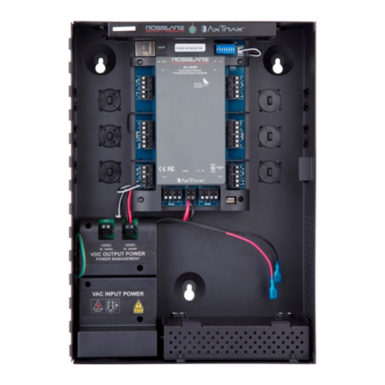
Figure 1: AC-225X-B Panel Layout
Table 2: Axtraxng Capabilities
Client-Server Structure
Configurable Links
Technical Specifications
AC-225X-DIN
AC-225X-B Installed in ME-1015
AC-225X-B Panel Setup
Figure 2: AC-225X-B Sample Configuration
Inputs Wiring - Non-Supervised Inputs
Inputs Wiring - Supervised Inputs
Figure 3: Inputs Wiring - Non-Supervised Inputs
Outputs Wiring
Figure 4: Door Lock - Failed Close
Figure 5: Door Lock - Failed Open
Power Supply
Figure 6: Wiring between PM-10 and AC-225X-B
AC-225X-B Wiring Communications
Figure 7: AC-225X-B Wiring Communications
Reader
MD-Io84B
MD-D02B
Figure 8: Reader Wiring
Figure 9: Connector Location for MD-IO84B or MD-D02B Expansions
Input and Output Connections
Input Types
Normally Open Input Connection
Figure 10: Normally Open Input Connection
Normally Closed Input Connection
Normally Open Supervised Single Resistor Input Connection
Normally Open Supervised Double Resistor Input Connection
Figure 11: Normally Closed Input Connection
Figure 12: Normally Open Supervised Input Connection (Single Resistor)
Normally Closed Supervised Single Resistor Input Connection
Figure 13: Normally Open Supervised Input Connection (Double Resistor)
Figure 14: Normally Closed Supervised Input Connection (Single Resistor)
Normally Closed Supervised Double Resistor Input Connection
Inputs Description
Request-To-Exit (REX) Button Input
Door Monitor Input
Figure 15: Normally Closed Supervised Input Connection (Double Resistor)
General Purpose Inputs
Outputs
Card Readers and Keypads
AC-225X-B Hardware Settings
DIP Switch Configuration
Figure 16: DIP Switches
Table 3: DIP Switches and Their Functions
Access Control Panel Baud Rate
Access Control Panel Type
Table 4: Switch Baud Rates
Table 5: Possible Hardware Settings
Access Control Panel Addressing
Table 6: Available Panel Addresses
Communications
Serial Network Connection
RS-232 Connection to the Computer
Figure 17: RS-232 Panel Connection to PC
RS-485 Connection to the Computer
Figure 18: RS-485 Panel Connection to PC
Table 7: RS-232 Connection
Daisy Chaining
Figure 19: Daisy Chaining
TCP/IP Network Connection
LAN and WAN Requirements
Figure 20: Connecting Multiple Access Control Panels to AC-225IP
Figure 21: Connecting a Single Control Panel with MD-N32
Figure 22: Connecting Multiple Access Control Panels with MD-N32
Declaration of Conformity
Radio Equipment Directive (RED)
Rohs Directive
UL 294 7Th Edition
Table 8: UL 294 Access Control Performance Ratings
Limited Warranty
Advertisement
Quick Links
1
Table of Contents
2
Table 1: Description of Ac-225X-B Panels
3
Figure 1: Ac-225X-B Panel Layout
4
Technical Specifications
5
Ac-225X-B Installed in Me-1015
6
Ac-225X-B Panel Setup
7
Ac-225X-B Wiring Communications
Download this manual
AC-225x-B Series
Expandable 2-Reader Networked
Access Control Panel
Hardware Installation and User Manual
Models:
AC-225-Bx
AC-225-DIN
AC-225IP-Bx
AC-225IP-DIN
Table of
Contents
Previous
Page
Next
Page
1
2
3
4
5
Advertisement
Table of Contents
Need help?
Do you have a question about the AC-225-B Series and is the answer not in the manual?
Ask a question
Questions and answers
Related Manuals for Rosslare AC-225-B Series
Control Panel Rosslare AC-020 Hardware Installation And User's Manual
Indoor dual-door standalone controller (61 pages)
Control Panel Rosslare AC-215-Bx Installation Manual And User's Manual
Ac-215x-b series 2-reader networked access control panel (40 pages)
Control Panel Rosslare AC-425x-B Series Installation And User Manual
Expandable 4-reader networked access control panel (46 pages)
Control Panel Rosslare AC-425 B Series Hardware Installation And User's Manual
Expandable 4-reader networked access (42 pages)
Control Panel Rosslare AC-425IP-BU Hardware Installation And User's Manual
Expandable 4-reader networked access control panel (42 pages)
Control Panel Rosslare AC-225IP-B Series Hardware Installation
Expandable 2-reader networked access control panel (43 pages)
Control Panel Rosslare AC-225-BE Hardware Installation
Expandable 2-reader networked access control panel (43 pages)
Control Panel Rosslare AC-225-BU Hardware Installation
Expandable 2-reader networked access control panel (43 pages)
Control Panel Rosslare AC-225IP-BE Hardware Installation
Expandable 2-reader networked access control panel (43 pages)
Control Panel Rosslare AC-225IP-BU Hardware Installation
Expandable 2-reader networked access control panel (43 pages)
Control Panel Rosslare HLX-24TH Series User Manual
Advanced wireless security panels (34 pages)
Control Panel Rosslare MD-D02B Installation Manual
2-reader expansion module for ax-225x-b control panel (3 pages)
Control Panel Rosslare AuraSys L-4 Hardware Installation Manual
(74 pages)
Control Panel Rosslare HomeLogix HLX-40 Installation And Programming Manual
Advanced wireless security panel (68 pages)
Control Panel Rosslare MD-IO84B Installation Manual
8 input/4 output expansion module for ac-225x-b/ac-425x/b control panels (3 pages)
This manual is also suitable for:
Ac-225ip-b series
Ac-225-din
Ac-225ip-din
Ac-225-ba
Ac-225-bb
Ac-225-be
...
Show all
Ac-225-bu
Ac-225ip-ba
Ac-225ip-bb
Ac-225ip-be
Ac-225ip-bu
Ac-225-bx
Ac-225ip-bx
Table of Contents
Print
Rename the bookmark
Delete bookmark?
Delete from my manuals?
Login
Sign In
OR
Sign in with Facebook
Sign in with Google
Upload manual
Upload from disk
Upload from URL


Need help?
Do you have a question about the AC-225-B Series and is the answer not in the manual?
Questions and answers