
Related Manuals for Rosslare AC-425IP-BU


Summary of Contents for Rosslare AC-425IP-BU
- Page 1 AC-425x-B Series Expandable 4-Reader Networked Access Control Panel Hardware Installation and User Guide Models: AC-425-B AC-425IP-B...
- Page 2 ROSSLARE. ROSSLARE reserves the right to revise and change this document at any time, without being obliged to announce such revisions or changes beforehand or after the fact.
-
Page 3: Table Of Contents
Table of Contents Table of Contents 1. Introduction ..................8 2. Technical Specifications ..............10 AC-425x-DIN ....................10 AC-425x-B Installed in ME-1015 ..............11 3. AC-425x-B Panel Setup ..............12 Inputs Wiring – Non-Supervised Inputs ............13 Inputs Wiring – Supervised Inputs .............. 14 Outputs Wiring ................... - Page 4 Table of Contents Card Readers and Keypads ................. 25 5. AC-425x-B Hardware Settings ............27 DIP Switch Configuration ................27 AC-425x-B Panel Baud Rate ................ 28 AC-425x-B Panel Type ................. 28 AC-425x-B Panel Address ................30 6. Communications ................32 Serial Network Connection .................
- Page 5 List of Figures List of Figures Figure 1: AC-425x-B Panel Layout ................9 Figure 2: Sample AC-425x-B Configuration ............. 12 Figure 3: Inputs Wiring – Non-supervised Inputs ............ 13 Figure 4: Door Lock – Failed Close ................14 Figure 5: Door Lock – Failed Open ................15 Figure 6: Wiring Between PM-10 and AC-425x-B ............
- Page 6 List of Tables List of Tables Table 1: DIP Switches and Their Functions .............. 27 Table 2: Switch Baud Rates ..................28 Table 3: Possible Hardware Settings ............... 28 Table 4: Available Panel Addresses ................. 31 Table 5: RS-232 Connection ..................33 AC-425x-B Series Hardware Installation and User Manual...
- Page 7 ROSSLARE exclusive warranty and liability is limited to the warranty and liability statement provided in an appendix at the end of this document.
-
Page 8: Introduction
Access Control Management Software, the system provides an ideal, modular, and expandable solution for commercial and institutional needs. It provides seamless integration with Rosslare's range of RFID proximity, PIN, Proximity & PIN, smartcard, and biometric readers with Rosslare’s selection of RFID credentials. -
Page 9: Figure 1: Ac-425X-B Panel Layout
Introduction Figure 1 shows the layout of the AC-425x-B panel. Figure 1: AC-425x-B Panel Layout AC-425x-B Series Hardware Installation and User Manual... -
Page 10: Technical Specifications
Technical Specifications Technical Specifications AC-425x-DIN Electrical Characteristics Operating Voltage 12 VDC, 1.5 A from a regulated power supply Maximum Input Current AC-425 Standby: 80 mA Maximum: 325 mA AC-425IP Standby: 120 mA Maximum: 370 mA General Inputs • 4 supervised high impedance inputs •... -
Page 11: Ac-425X-B Installed In Me-1015
Technical Specifications Environmental Characteristics Operating Temperature Range 0°C to 49°C (32°F to 120°F) Operating Humidity Range 0 to 85% (non-condensing) Dimensions Height x Width x Depth 193 x 136.5 x 39 mm (7.6 x 5.4 x 1.5 in.) Weight 0.36 kg (12.7 oz) AC-425x-B Installed in ME-1015 Electrical Characteristics –... -
Page 12: Ac-425X-B Panel Setup
AC-425x-B Panel Setup AC-425x-B Panel Setup Each AC-425x-B panel controls 2 or 4 doors (up to 8 doors with MD-D04B). The panels connect together in a network and are controlled by a central server computer, running the AxTraxNG/AxTraxPro Access Control Management Software. -
Page 13: Inputs Wiring - Non-Supervised Inputs
AC-425x-B Panel Setup Inputs Wiring – Non-Supervised Inputs Figure 3 presents a detailed view of the non-supervised inputs and their connection options. Figure 3: Inputs Wiring – Non-supervised Inputs AC-425x-B Series Hardware Installation and User Manual... -
Page 14: Inputs Wiring - Supervised Inputs
AC-425x-B Panel Setup Inputs Wiring – Supervised Inputs When wiring the AC-425x-B for supervised inputs, resistors should be placed on the input switch and not on the terminal block. For more details, refer to Chapter 4. Outputs Wiring Figure 4 and Figure 5 illustrate wiring for two main types of 12 VDC electrical release mechanisms. -
Page 15: Power Supply
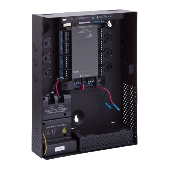
AC-425x-B Panel Setup Figure 5: Door Lock – Failed Open Power Supply Figure 6 illustrates wiring between the PM-10 power management board and the AC-425x-B. Make sure the connection polarity is correct, (+) to (+) and (-) to (-). Connect the power to the input power terminals of the control panel. It is recommended to add a 12 VDC lead acid backup battery (requires the ME-1015 Power Management Enclosure) to have uninterrupted operation in case main power supply fails. -
Page 16: Figure 6: Wiring Between Pm-10 And Ac-425X-B
AC-425x-B Panel Setup Figure 6: Wiring Between PM-10 and AC-425x-B AC-425x-B Series Hardware Installation and User Manual... -
Page 17: Ac-425X-B Wiring Communications
AC-425x-B Panel Setup AC-425x-B Wiring Communications Figure 7 presents a detailed view of the access control panel with all its necessary wiring for communications. Figure 7: AC-425x-B Wiring Communications Readers Proximity and keypad readers are supplied with a limited cable. The color of the cable cover represents the cable’s function according to Wiegand standards (Figure 8). -
Page 18: Md-Io84B
AC-425x-B Panel Setup Figure 8: Reader Wiring MD-IO84B The MD-IO84B is an optional I/O expansion board that adds 4 relay outputs and 8 supervised inputs to the Access Control Panel. Attach the MD-IO84B to the AC- 425x-B's expansion slot, as marked in red in Figure 9). Figure 9: Connector Location for MD-IO84B or MD-D04B Expansions For more information, see the MD-IO84B Installation and User Guide. -
Page 19: Input And Output Connections
Input and Output Connections Input and Output Connections This chapter describes the AC-425x-B access control panel's input and output connections. Input Types There are four input types: Normally Closed (N.C.) Normally Open (N.O.) Single EOL resistor Double EOL resistor ... -
Page 20: Normally Closed Input Connection
Input and Output Connections 4.1.2 Normally Closed Input Connection A Normally Closed Input has two states: Switch Closed – Normal State: Loop resistance = 0 (short circuit) Switch Open – Abnormal State: Loop resistance = Infinite (open circuit) Figure 11: Normally Closed Input Connection 4.1.3 Normally Open Supervised Single EOL Resistor Input Connection... -
Page 21: Normally Open Supervised Double Eol Resistor Input Connection
Input and Output Connections 4.1.4 Normally Open Supervised Double EOL Resistor Input Connection Connect a 2.2 kΩ resistor in series to the input switch contacts. Connect an 8.2 kΩ resistor parallel to the input switch contacts. A Normally Open Supervised Input has 3 states: Switch Open –... -
Page 22: Normally Closed Supervised Double Eol Resistor Input Connection
Input and Output Connections 4.1.6 Normally Closed Supervised Double EOL Resistor Input Connection Connect a 2.2 kΩ resistor in series to the input switch contacts. Connect an 8.2 kΩ resistor parallel to the input switch contacts. A Normally Closed Supervised Input has 3 states: Switch Closed –... -
Page 23: Door Monitor Input
Input and Output Connections Scenario Setting Door 3 – IN3 Door 4 – IN4 Door 5 – IN5 Door 6 – IN6 Door 7 – IN7 Door 8 – IN8 4.2.2 Door Monitor Input The Door Monitor input typically connects to a Normally Closed door sensing micro-switch for door status monitoring. -
Page 24: Outputs
IN5 to IN12 MD-D04B IN5 to IN8 except the dedicated inputs Outputs Rosslare Security recommends the use of suppression diodes for all outputs that activate an inductive load. 4.3.1 Door Lock There are two types of door locking devices: Fail open (fail secure) ... -
Page 25: Card Readers And Keypads
Input and Output Connections For UL installations, the installer must configure the system as fail-safe to comply with NFPA (National Fire Protection Association) regulations. Card Readers and Keypads Each access control panel can be connected to a maximum of four readers or 8 readers when using MD-D04B. - Page 26 Input and Output Connections Scenario Setting Door 7 – Reader 7 IN/OUT Door 8 – Reader 8 IN/OUT Use the AxTraxNG/AxTraxPro Access Control Management Software to set the readers for IN or OUT use and to set the data transmission format for each reader. The reader’s tamper output connects to the access control panel's Reader-Tamper input.
-
Page 27: Ac-425X-B Hardware Settings
AC-425x-B Hardware Settings AC-425x-B Hardware Settings DIP Switch Configuration The DIP switches in the access control panel determine the baud rates for serial communication, control panel type, and the device address, as summarized in Table 1. Table 1: DIP Switches and Their Functions DIP Switch Function The panel's communication baud rate The panel type defines the number of readers for each... -
Page 28: Ac-425X-B Panel Baud Rate
AC-425x-B Hardware Settings AC-425x-B Panel Baud Rate The AC-425x-B panel serial port baud rate, set in DIP switches 1 and 2, defines the communication speed for connecting with a PC in a network connection. The default baud rate is set to 9600 bits per second. Table 2 lists the status of Switches 1 and 2 and the baud rate: Table 2: Switch Baud Rates Switch 1... - Page 29 AC-425x-B Hardware Settings Connectors Description Setup Door monitor input (IN 3) Door 2: Request to exit (IN 2) Door monitor input (IN 4) Readers Reader1 – Door1 Door Entry or Exit Reader2 – Door2 Door Exit or Entry Reader3 – Door1 Door Entry or Exit Reader4 –...
-
Page 30: Ac-425X-B Panel Address
AC-425x-B Hardware Settings Connectors Description Setup Reader5 (Door3 IN/OUT) Reader6 (Door4 OUT/IN) Reader7 (Door3 IN/OUT) Reader8 (Door4 OUT/IN) One reader per door with 8 readers (MD-D04B) Outputs Door1 Lock output (OUT 1) Door2 Lock output (OUT 2) Door3 Lock output (OUT 3) Door4 Lock output (OUT 4) -
Page 31: Table 4: Available Panel Addresses
AC-425x-B Hardware Settings Table 4: Available Panel Addresses Address Switch 4 Switch 5 Switch 6 Switch 7 Switch 8 The AC-425x-B panel address is defined in the AxTraxNG/AxTraxPro Access Control Management Software. The DIP switch and the software must be set to the same address. AC-425x-B Series Hardware Installation and User Manual... -
Page 32: Communications
Communications Communications Communication lines are used to upload and download information between the AC-425x-B panel and the AxTraxNG/AxTraxPro server. When the access control panel and the computer are communicating, the system’s two LEDs flash accordingly. The RX LED flashes when the controller receives data ... -
Page 33: Rs-232 Connection To The Computer
Communications 6.1.1 RS-232 Connection to the Computer Set the J1 switch to the RS-232 position. The RS-232 connection can only connect a single access control panel to the computer (Figure 17). Figure 17: RS-232 Panel Connection to PC The distance between the computer and the access control panel must be no more than 150 feet (50 meters). -
Page 34: Daisy Chaining
Communications The AC-425x-B supports the 2-wire RS-485 interface, which can significantly increase the distance between the server and the last panel. To use the RS-485 interface, the panels must be connected in a daisy-chain formation with an MD- 14U RS-485 to RS-232 adapter (Section 6.1.3). The recommended cable type to be used is STP cat5 (shielded twisted pair category 5). -
Page 35: Tcp/Ip Network Connection
IP port can support up to 32 AC-425IP-B panels (Figure 20). Figure 20: MD-N32 Configuration Connecting a Single Panel To connect to a TCP/IP network using AC-425 non-IP models, add Rosslare's MD- N32 TCP/IP to RS-232 gateway converter. -
Page 36: Lan And Wan Requirements
When using an MD-N32, for a single panel, either an RS-232 cable or Rosslare's MD-14U RS-485 to RS-232 converter can be used. To connect an MD-N32 to more than one panel (up to 32 panels), Rosslare's MD- 14U RS-485 to RS-232 converter must be used. Connect the MD-14U between the RS-485 access control panel network and the MD-N32 converter (Figure 22). -
Page 37: Declaration Of Conformity
Declaration of Conformity Declaration of Conformity FCC ID = GCD-AC425x This device complies with Part 15 of the FCC Rules. Operation is subject to the following two conditions: This device may not cause harmful interference. This device must accept any interference received, including interference ... -
Page 38: Radio Equipment Directive (Red)
Radio Equipment Directive (RED) Radio Equipment Directive (RED) Under our sole responsibility that the following labeled AC-425-Bx, AC-425-DIN, AC-4215IP-Bx, and AC-425IP-DIN are tested to conform to the EU Radio Equipment Directive – RED 2014/53/EU – in electrical and electronic equipment. AC-425x-B Series Hardware Installation and User Manual... -
Page 39: Rohs Directive
RoHS Directive RoHS Directive Under our sole responsibility that the following labeled AC-425-Bx, AC-4215-DIN, AC-425IP-Bx, and AC-425IP-DIN are tested to conform to the Restriction of Hazardous Substances (RoHS) directive – 2011/65/EU – in electrical and electronic equipment AC-425x-B Series Hardware Installation and User Manual... -
Page 40: Limited Warranty
The full ROSSLARE Limited Warranty Statement is available in the Quick Links section on the ROSSLARE website at www.rosslaresecurity.com. Rosslare considers any use of this product as agreement to the Warranty Terms even if you do not review them. AC-425x-B Series Hardware Installation and User Manual... - Page 42 755 8610 6101 Europe support.cn@rosslaresecurity.com Rosslare Israel Ltd. 22 Ha'Melacha St., P.O.B. 11407 India Rosh HaAyin, Israel Rosslare Electronics India Pvt Ltd. Tel: +972 3 938-6838 Fax: +972 3 Tel/Fax: +91 20 40147830 Mobile: 938-6830 +91 9975768824 support.eu@rosslaresecurity.com sales.in@rosslaresecurity.com 0706-0960748+01...
Need help?
Do you have a question about the AC-425IP-BU and is the answer not in the manual?
Questions and answers