Table of Contents
Advertisement
Quick Links
Advertisement
Table of Contents

Related Manuals for Emerson Liebert ITA


Summary of Contents for Emerson Liebert ITA
- Page 1 ® ™ Liebert User Manual – 16-20kVA UPS...
-
Page 3: Safety Precautions
When operating Emerson products, the operation personnel must observe the safety rules in the industry, the general safety points and special safety instructions provided by Emerson. - Page 4 Conformity and standards The UPS complies with 2006/95/EC (LV Safety) and 2004/108/EC (EMC), with Australia and New Zealand EMC Framework (C-Tick) and with the following product standards for UPS: IEC 62040: 2008 General and safety requirements IEC62040-2: EMC requirements, Class C2 compliant ...
-
Page 5: Table Of Contents
Contents Chapter 1 Product Introduction ............................1 1.1 Features................................1 1.2 Model Configurations ............................1 1.3 Appearance And Components ..........................2 1.3.1 Appearance ............................... 2 1.3.2 Components .............................. 2 1.4 Operating Principle ............................... 3 ... - Page 6 Chapter 3 Parallel UPS Installation And Commissioning ....................27 3.1 Features................................27 3.2 Requirements ..............................27 3.3 Mechanical Installation............................27 3.4 Connecting Power Cables ..........................28 3.4.1 Connecting I/O Cables..........................28 3.4.2 Connecting Parallel Cables ........................29 ...
- Page 7 5.4 EPO ..................................49 5.5 Auto Restart ................................ 49 5.6 UPS Reset ................................49 5.7 Language Selection ............................50 5.8 Changing Current Date And Time........................50 5.9 Control Password..............................50 Chapter 6 Communication..............................51 ...
-
Page 9: Chapter 1 Product Introduction
ITA 16kVA and 20kVA UPS (UPS for short) is an intelligent online UPS system with sine wave output ® developed by Emerson Network Power Co., Ltd. The UPS offers reliable and high quality AC power to the precision instrument. The UPS adopts modular design, and rack/tower installation can be used depending on your requirements. It is applicable to supplying AC power to small scale computer center, network, communication system, automatic control system and precision instrument. -
Page 10: Appearance And Components
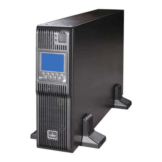
Chapter 1 Product Introduction 1.3 Appearance And Components 1.3.1 Appearance The UPS appearance is shown in Figure 1-1. Figure 1-1 UPS appearance 1.3.2 Components Front panel As shown in Figure 1-2, the UPS front panel provides ventilation holes, operation and display panel, LED indicators, DIP switch and battery cold start button. -
Page 11: Operating Principle
Chapter 1 Product Introduction 1.4 Operating Principle The operating principle of the UPS is shown in Figure 1-4. Bypass input Bypass Input filter Output Main input Inverter Output filter Rectifier /PFC Auxiliary power Battery Charger controller Figure 1-4 UPS operating principle 1. -
Page 12: Normal Mode
Chapter 1 Product Introduction Normal mode Battery mode Bypass mode Maintenance Bypass mode Figure 1-5 Operation schematic diagram For the LED indicators introduced in this section, refer to 4.1.1 LED Indicators. 1.5.1 Normal Mode When the mains input is normal, the load is supplied with voltage-stabilizing and frequency-stabilizing power by the mains after processing of the rectifier and the inverter, and meanwhile, the charger is charging the battery. -
Page 13: Battery Mode
Note When the UPS has malfunctions and can not working normally, please get in touch with the nearest Emerson branch office or local service center. It is prohibited to repaire the UPS by yourself, otherwise the personnel injury and damage to the equipment will occur. - Page 14 Chapter 1 Product Introduction Table 1-2 Specifications Specifications Item UHA3R-0160L UHA3R-0200L Rated voltage 380Vac/400Vac/415Vac 304Vac ~ 478Vac, at full load Voltage range 228Vac ~ 304Vac, linear derating 228Vac, at half load Input Rated frequency 50Hz/60Hz Frequency range 40Hz ~ 70Hz Power factor ≥...
-
Page 15: Chapter 2 Single Ups Installation And Commissioning
The UPS should be installed by a qualified engineer according to the information contained in this chapter. If any problem is found, please get in touch with Emerson local service center immediately. The UPS shall not be powered on without approval of the commissioning engineer. - Page 16 Chapter 2 Single UPS Installation And Commissioning equipment (see Figure 2-1), to avoid obstructing the UPS ventilation and heat dissipation. Otherwise, the UPS internal temperature will rise, which will shorten the UPS life. If necessary, an indoor exhaust fan should be installed to keep the indoor temperature from rising. An air filter should be used in a dusty environment where the UPS is to be operated.
-
Page 17: Installation Tools
Chapter 2 Single UPS Installation And Commissioning When the UPS uses an external battery, you must install a battery protective device (such as fuse or circuit breaker) in areas near the battery, and use the shortest wiring distance for the connection between the protective device and the battery. -
Page 18: Battery Input
(to load). 2.3.2 Battery Input If the battery module option is provided by Emerson, the battery module has a built-in overcurrent protective device. Otherwise, the external battery cabinet should provide DC compatible circuit breaker to provide the overcurrent protection for the UPS and its batteries. -
Page 19: Rack Installation
Chapter 2 Single UPS Installation And Commissioning Support base extension Support base Fastening Figure 2-4 Connecting the support base with support base extension 3. Place the UPS on the support bases and support base extensions, as shown in Figure 2-5. Battery module (4 pcs) Support... - Page 20 Chapter 2 Single UPS Installation And Commissioning Installation hole (6 pcs) Left guide rail Right guide rail Figure 2-7 Appearance of the guide rail Distinguish the guide rail screw and the panel screw according to Figure 2-8. Guide rail screw Panel screw Figure 2-8 Appearance of the screw 2) Adjust the length of the guide rail according to the dimensions of the rack.
-
Page 21: Connecting Power Cables
Chapter 2 Single UPS Installation And Commissioning 3. Place the UPS on the guide rails in the rack, and push it completely into the rack. Use four M6 × 16 screws to fix the UPS in the rack through the brackets, as shown in Figure 2-11. Guide rail Rack Bracket... -
Page 22: Connecting I/O Cables
Chapter 2 Single UPS Installation And Commissioning Rated current (A) 1, 2 UPS rated Mains input current upon battery Gross output current at full load Battery discharging current upon power (kVA) charging with max. ability min. battery voltage 380V 400V 415V 380V 400V... - Page 23 Power distribution mode There are two modes for UPS power distribution: using the single power output distribution unit (POD, optional) provided by Emerson, self-distribution. According to user’s requirements, the I/O cable connections are divided into four types: 3-in 3-out, common source configuration (factory default), 3-in 3-out, split-bypass configuration, 3-in 1-out, common source configuration, 3-in 1-out, split-bypass configuration.
- Page 24 Chapter 2 Single UPS Installation And Commissioning 2. Self-distribution The I/O cable connection procedures of the self-distribution for the four types are as follows: 3-in 3-out, common source configuration (factory default) 1. Remove the protective cover A of the I/O terminal block. 2.
- Page 25 Chapter 2 Single UPS Installation And Commissioning 3-in 1-out, common source configuration Warning The factory default of the UPS is 3-in 3-out, common source configuration. If you need to change the power distribution mode to 3-in 1-out ,follow the steps described in the next section Changing power distribution mode. Continue the input and output power cable connection and power-on commissioning after confirming that the change has been successful.
- Page 26 Chapter 2 Single UPS Installation And Commissioning 3-in 1-out, split-bypass configuration Warning The factory default of this product is 3-in 3-out, common source configuration. If you need to change the power distribution mode of the main UPS to 3-in 1-out according to the steps described in the next section Changing power distribution mode. Continue the input and output power cable connection and power-on commissioning after confirming that the change has been successful.
- Page 27 Chapter 2 Single UPS Installation And Commissioning Figure 2-21 Label Changing power distribution mode Note This product is compatible with 3-in 3-out and 3-in 1-out, factory default: 3-in 3-out. Change the format according to the following steps if you need to change the power distribution mode. ...
-
Page 28: Connecting Battery Cables
Chapter 2 Single UPS Installation And Commissioning 2.5.2 Connecting Battery Cables Notes 1. If the battery module is not configured, this product needs to be equipped with positive and negative batteries. Each battery string ranges from 15-cell to 20-cell, and 12V for each cell. 2. - Page 29 Chapter 2 Single UPS Installation And Commissioning First cell Second cell Third cell Sixteenth cell + + + + …… Bat - - - - - First cell Second cell Third cell Sixteenth cell Bat N + + + + ……...
- Page 30 Chapter 2 Single UPS Installation And Commissioning Bat N Bat + Bat - Figure 2-27 Cable connection diagram of the positive battery module Liebert ITA 16kVA And 20kVA UPS User Manual ®...
-
Page 31: Single Ups Commissioning
Chapter 2 Single UPS Installation And Commissioning Bat N Bat + Bat - Figure 2-28 Cable connection diagram of the negative battery module 2.6 Single UPS Commissioning 2.6.1 Check Before Start-Up 1. Check and confirm that the power distribution mode of the UPS and the POD (if configured) is correct, that the connection of the power cables and signal cables is correct and there is no short circuit. - Page 32 Chapter 2 Single UPS Installation And Commissioning Parameters Default value Parameters setting System Configuration Single Single ECO Mode Normal Normal Set the parameter according to the actual power grid, 50Hz/60Hz can be Output frencency level* 50Hz selected Set the parameter according to the actual power grid, 380V/400V/415V can Output voltage level* 380V be selected...
- Page 33 Chapter 2 Single UPS Installation And Commissioning Set ‘Single Group Batt Cap’ according to the actual total battery capability, for ‘Battery Cells Number’, 30, 32, 34, 36, 38 or 40 can be selected, set ‘Equalize Charge Allowed’, ‘Temp Compensation’ and ‘Batt Temp Sensor Position’ (battery temperature sensor is optional) according to the user requirement.
-
Page 34: Normal Mode Start-Up
Chapter 2 Single UPS Installation And Commissioning Single ITA 016kVA Single ITA 016kVA 14:30:36 14:30:36 Output Voltage Level Protocol 380V YDN23 YDN23 Velocity LBS Function MASTER 3 Phase Output or 1 Phase Output Three NONE SLAVE MASTER Three Single Command password ***** Settings Settings... -
Page 35: Chapter 3 Parallel Ups Installation And Commissioning
Chapter 3 Parallel UPS Installation And Commissioning Chapter 3 Parallel UPS Installation And Commissioning This chapter introduces the features, requirements, installation and commissioning of the parallel system. The UPS parallel system provides the user with N + X (2 ≤ N + X ≤ 4) parallel configuration, N stands for the basic parallel sets, X stands for the redundant sets. -
Page 36: Connecting Power Cables
Power distribution mode There are two modes for UPS parallel power distribution: using the 1 + 1 parallel POD (optional) provided by Emerson, self-distribution. The I/O cable connections are divided into four types: 3-in 3-out, common source configuration (factory default), 3-in 3-out, split-bypass configuration, 3-in 1-out, common source configuration, 3-in 1-out, split-bypass configuration. -
Page 37: Connecting Parallel Cables
Chapter 3 Parallel UPS Installation And Commissioning User input power User output power distribution unit distribution unit UPS1 Input cable Output cable UPS2 UPS3 Figure 3-2 Block diagram of three UPSs parallel system Warning Configure each UPS with extenal input MCB and extenal output MCB when carring out the power distribution for the parallel system, as shown in Figure 3-2. - Page 38 Figure 3-3 Cable connection schematic diagram of 3 + 1 parallel system Note 1. The Emerson parallel cables must be used for the parallel system. 2. The parallel communication fault occurs during the parallel commissioning, check whether the connection of the parallel cables is correct, and whenther the pin1~ pin9 of the parallel cables are connected.
-
Page 39: Connecting Battery Cables
Chapter 3 Parallel UPS Installation And Commissioning Warning 1. The default setting of the DIP switch is ‘1’. However, you should set the DIP switch position for the parallel system according to the descriptions listed in Table 3-2. Otherwise, a UPS fault will occur. 2. - Page 40 Chapter 3 Parallel UPS Installation And Commissioning Sharing battery strings Using the shared battery strings in the parallel system can save investment in equipment for the users. Note 1. If the battery strings (four standard battery modules, option) are shared in parallel system, the backup time of the battery module ranges from two minutes to three minutes at full load.
-
Page 41: Commissioning Parallel System
Chapter 3 Parallel UPS Installation And Commissioning Note 1. For the parallel system using the shared battery strings, make sure that the LCD settings are correct. Refer to 3.5.2 Parallel System Parameters Settings for details. 2. For the parallel system using the shared battery strings, the ‘Single Group Batt Cap’ on the LCD setting of each UPS stands for total capacity of the battery strings, and each UPS can calculate the shared battery capacity automatically. -
Page 42: Power-On Commissioning For Parallel System
Chapter 3 Parallel UPS Installation And Commissioning Table 3-3 Parallel parameters setting Parameters Default value Parallel parameters setting Single Group Batt Cap 0014 Set the parameter according to the actual battery capicitity Battery Cells Number Set the parameter according to the actual battery number Equalize Charge Allowed Enabled Set the parameter according to the actual battery charicteristic... -
Page 43: Installation And Commissioning For Double Bus System
Chapter 3 Parallel UPS Installation And Commissioning tested will enter bypass state. Because the POD output MCB of the other UPS is not closed, the Input Disconnect Fault will be displayed, and Bypass unable to trace or Bypass protection may occur, ignore these alarms at the moment. -
Page 44: Installing External Protective Device
Chapter 3 Parallel UPS Installation And Commissioning Bypass input Bypass Output UPS 1 Main input Main Bypass Output UPS 2 Main Connect to load LBS cable Bypass input Bypass Output UPS 3 Main input Main Bypass Output UPS 4 Main Note: UPS1 and UPS2 are master system, UPS3 and UPS4 are slave system Figure 3-9 LBS system schematic diagram Note... -
Page 45: Setting Parameters Of Double Bus System
Chapter 3 Parallel UPS Installation And Commissioning DB9 male port DB9 female port oN oN oA oB oC PE PE UPS 1 DB9 male port DB9 female port oN oN oA oB oC PE PE UPS 2 LBS cable oN oN oA oB oC PE PE UPS 3 oN oN oA oB oC... - Page 46 Chapter 3 Parallel UPS Installation And Commissioning Unit 1# ITA 016 kVA Unit 1# ITA 016kVA 14:30:36 14:30:36 Shared Battery Parallel Redundant Units Disabled Enabled Disabled System Configuration Parallel ECO Mode Normal Single Parallel Normal Parallel requisite units Output frequency Level 50Hz 50Hz 60Hz...
-
Page 47: Chapter 4 Operation And Display Panel
Chapter 4 Operation And Display Panel Chapter 4 Operation And Display Panel This chapter introduces the functions and use of the components on the UPS operation and display panel, and provides LCD display information, including the LCD screen types, detailed menu messages, prompt windows message and UPS alarm list. -
Page 48: Control Buttons
Chapter 4 Operation And Display Panel 4.1.3 Control Buttons The operation and display panel provides five control buttons, the functions are described in Table 4-3. Table 4-3 Description of control buttons Control button Silkprint Description Used to disconnect the load power and close the rectifier, the inverter, the EPO switch static bypass and the battery Inverter on... -
Page 49: Primary Screen
Chapter 4 Operation And Display Panel 4.2.2 Primary Screen After the self-test of the UPS, the primary screen shown in Figure 4-3 will appear. The primary screen is composed of four windows: system information window, data window, menu window and keypad window. System Unit 1# ITA 016kVA... -
Page 50: Detailed Description Of Menus
Chapter 4 Operation And Display Panel 4.3 Detailed Description Of Menus The following description refers to the LCD primary screen shown in Figure 4-3. System information window The system information window displays the current time and the UPS name. You are not required for operating the information of this window. -
Page 51: Prompt Window
Chapter 4 Operation And Display Panel Menu Item Explanation Comm2 baud rate For internal communication only, which cannot be set Comm3 baud rate Set the communication baud rate of the SNMP card port Communication address For RS485 communication Single Group Batt Cap Set the total battery capacity according to the configuration Set the battery cell. -
Page 52: Ups Alarm Message List
Chapter 4 Operation And Display Panel Prompt Meaning The number of paralleled inverters already turned on is insufficient to carry the Turn on more UPS to carry current load current load, thus more inverters are required The battery maintenance test discharges the battery completely. A prompt screen Battery will be depleted, confirm or cancel will appear to require your confirmation. - Page 53 Chapter 4 Operation And Display Panel Alarm message Description This alarm is triggered by an inverter software program when the amplitude or frequency of bypass voltage is too high or too low. The amplitude threshold is fixed for ±10% rating. This alarm will automatically recover when the bypass voltage is normal.
- Page 54 (3-in 3-out or 3-in 1-out) trace Note: If the alarm is caused through setting the software value by Emerson authorized engineer, and when you wish to change the setting values, please get in touch with the Emerson local customer service center Liebert ITA 16kVA And 20kVA UPS User Manual ®...
-
Page 55: Chapter 5 Ups Operation Instructions
Chapter 5 UPS Operation Instructions Chapter 5 UPS Operation Instructions This chapter gives a detailed description of the UPS operation procedures. During the operation, the buzzer alarm may appear, at this point, you can press the ALARM CLEAR button to silence the audible alarm. -
Page 56: Transfer From Inverter Mode To Maintenance Bypass Mode
Chapter 5 UPS Operation Instructions 5.2.4 Transfer From Inverter Mode To Maintenance Bypass Mode When the UPS is running in Normal mode, you can use this procedure to make the load transfer from inverter output to maintenance bypass. Caution 1. Before performing this procedure, you should check the LED information first, and make sure the bypass is normal and synchronizes with the inverter. -
Page 57: Epo
Chapter 5 UPS Operation Instructions Figure 5-1 Configuration of the UPS with external maintenance bypass For the UPS system which the distribute power is accomplished by user, if you need to isolate the UPS from AC power, disconnect the external input MCB. (If the main and bypass are independently powered, close the two input MCBs). -
Page 58: Language Selection
Chapter 5 UPS Operation Instructions Note 1. The rectifier restarts, and the bypass supplies power to the load. When the rectifier starts, the fault indicator blinks. When the rectifier runs in normal operation state (about 30 seconds later), the fault indicator will turn off. 2. -
Page 59: Chapter 6 Communication
Emerson have network communication capability. The SIC card can also be used with the Network Shutdown designed by Emerson to provide safe automatic shutdown function for the computer, in which the Network Shutdown has been installed, to protect data and reduce loss. -
Page 60: Connection Cables For Dry Contact Port
Chapter 6 Communication Extended dry contact card Except for the function of the UPS dry contact card, the extended dry contact card provides RS232 and RS485 communication function to support the JBUS/MODBUS (RTU) communication protocol, and provides four routes analog acquisition function. Refer to the corresponding user manual for the installation and operation guide. -
Page 61: Connecting Usb Communication Cables
Chapter 6 Communication In emergency conditions, close the REPO switch (prepared by users) to shut down the rectifier and inverter, and the UPS is powered off. In normal condition, the REPO switch cannot cut off the UPS input power. If a switch of electronic control tripping function is adopted at the UPS input, the REPO switch can help the switch trip and thus cut off the UPS input power. -
Page 62: Chapter 7 Maintenance
Emerson is not liable for the environment results caused by failure to comply with the notices in this section or to use the waste battery recycle system provided by Emerson. -
Page 63: Cleaning Ups
Chapter 7 Maintenance 7.3 Cleaning UPS Clean the UPS periodically, especially the ventilation holes, to ensure free airflow inside the UPS. If necessary, clean the UPS with a vacuum cleaner. Confirm that the ventilation holes are unobstructed. 7.4 Checking UPS State It is recommended to check the UPS operation status once every half year. -
Page 64: Chapter 8 Options
Chapter 8 Options Chapter 8 Options This chapter introduces the options of the UPS. 8.1 Option List See Table 8-1 for the option list. Table 8-1 Option list Option name Model Remark U16-07C1 Battery module with built-in 16-cell 12V (7.2Ah) batteries Battery module U16-09C1 Battery module with built-in 16-cell 12V (9Ah) batteries... -
Page 65: Appearance Of Battery Module
Chapter 8 Options Note 1. The battery loop and the AC input are not insulated, so the hazardous voltage may exist between the battery port and the earth. Never touch them by hand to avoid electrical shock. 2. See Figure 2-25 and Figure 2-26 for the appearance and the length of the battery cable (battery module accessory). If the longer cables are needed, please contact the dealers. -
Page 66: Pod
Chapter 8 Options Table 8-3 Backup time list 1 No. of the Backup time battery module 18kW 14.4kW 13.5kW 10.8kW 7.2kW 1h30m Table 8-4 Backup time list 2 No. of the Backup time battery module 5.4kW 4.5kW 3.6kW 1.8kW 1.5kW 1h25m 2h30m 1h25m... - Page 67 Chapter 8 Options Main input MCB Maintenance bypass MCB Bypass input MCB Output MCB Front panel of the single POD User terminal block (Silkprint: USER) oN oN oA oB oC mN bN mA bA mB bB mC bC oN oN oA oB oC mN bN mA bA mB bB mC bC PE terminal...
-
Page 68: Communication Cables
Chapter 8 Options User terminal block (Silkprint: USER) oN oN oA oB oC mN bN mA bA mB bB mC bC oN oN oA oB oC mN bN mA bA mB bB mC bC oN oN oA oB oC mN bN mA bA mB bB mC bC PE terminal PE terminal UPS terminal block... -
Page 69: Battery Cabinet
Chapter 8 Options Table 8-10 Double bus parts Type Name Description Appearance Be used to form LBS system. UHRK2S671SL5 LBS cable Two LBS cables are recommended 16A single-phase LTS Front panel 前面板 (Height: 1U) is a single pole single-phase double-throw switch, which is UF-LTS16-1P load transfer used for the priority load with... -
Page 70: Communication Options And Monitoring Options
Chapter 8 Options The standard battery cabinets are listed in Table 8-11. Table 8-11 Standard battery cabinet list Corresponding Battery cabinet type UPS power Configuration Dimension/Weight battery (CSB) Four layers, can load 32-cell batteries; configure 250A ABB 800mm × 1100mm × 2000mm PM32-75C4-2-50-A ≤... - Page 71 Chapter 8 Options Note 1. When using the SIC card to connec to the temperature sensor as battery temperature compensation, connect to the COM1 port of the SIC card, and set DIP switch of the temperature sensor to ‘1’. For the installation and setting of the SIC card, refer to RDU-SIC Card User Manual.
- Page 72 Network Power service technicians. While every precaution has been taken to ensure the accuracy and completeness of this literature, Emerson Network Power assumes no responsibility and disclaims all liability for damages resulting from use of this information or for any errors or omissions.
Need help?
Do you have a question about the Liebert ITA and is the answer not in the manual?
Questions and answers