
Related Manuals for OpenEye CM-512


Summary of Contents for OpenEye CM-512
- Page 1 Outdoor Speed Dome Camera User Manual Camera Accessories CM-512 CA-510G CA-510PML CA-510W CA-510PMS CA-510C CA-510PA25 CA-510P25 CA-510PA50 CA-510P50 www.openeye.net...
- Page 3 The information in this publication is provided “as is” without warranty of any kind. The entire risk arising out of the use of this information remains with recipient. In no event shall OPENEYE be liable for any direct, consequential, incidental, special, punitive, or other damages whatsoever...
-
Page 4: Important Safeguards
Important Safeguards Read Instructions Read all of the safety and operating instructions before using the product. Retain Instructions Save these instructions for future reference. Attachments / Accessories Do not use attachments or accessories unless recommended by the appliance manufacturer as they may cause hazards, damage product and void warranty. Installation Do not place or mount this product in or on an unstable or improperly supported location. - Page 5 Installation and Storage • Do not install the camera in areas of extreme temperatures in excess of the allowable range. ( -58°F ~ 122°F / -50°C ~ 50°C) • Avoid installing in humid or dusty places. The relative humidity must be below 90%.
- Page 6 Warning DANGEROUS HIGH VOLTAGES ARE PRESENT INSIDE THE ENCLOSURE. DO NOT OPEN THE CABINET. REFER SERVICING TO QUALIFIED PERSONNEL ONLY. Caution C A U T I O N RISK OF ELECTRIC SHOCK DO NOT OPEN CAUTION: TO REDUCE THE RISK OF ELECTRIC SHOCK, DO NOT REMOVE COVER (OR BACK).
-
Page 7: Table Of Contents
TABLE OF CONTENTS Introduction ........................... 11 Overview ............................ 11 Product Features ........................11 General Operation Requirements ....................12 System Configuration ......................12 Getting Started ..........................13 Box Contents ..........................13 Camera Overview ........................14 Dimensions ..........................14 Preparations for Dome Setup ....................15 Connections ........................... - Page 8 DNR ..........................34 Image Inverse ........................35 Freeze ..........................35 Aperture ..........................35 Stabilizer ........................... 35 Exit ............................ 35 Telemetry Control ........................36 Flip ............................ 36 Angle Adjusters ......................... 36 PT Position ........................37 Speed by Zoom ......................... 37 Auto Calibration......................... 37 Password ..........................
- Page 9 Speed ..........................43 Run Autoscan........................43 Exit ............................ 43 Pattern ........................... 44 Pattern Line ........................44 Record Start ........................44 Record End ........................44 Run Pattern ........................44 Exit ............................ 45 Home Setting ......................... 45 Home Function ........................45 Select Mode ........................45 Preset Point ........................
- Page 10 Schedule ..........................54 Switch ..........................54 Point ..........................54 Hour / Minute........................54 Mode ..........................54 Schedule Reset ......................... 55 Exit ............................ 55 Exit OSD ..........................55 Appendix A: Specifications ......................56 Camera Specifications ........................ 56 PTZ Specifications ........................57 Appendix B: OSD Menu Notes ....................
-
Page 11: Introduction
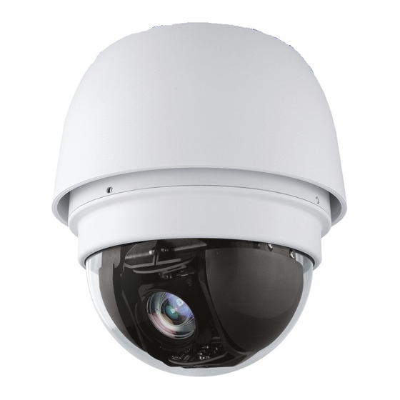
OpenEye recorders and keyboard controllers, making installation or configuration quick and easy. OpenEye’s CM-512 offers you the options that matter in total security protection. Equipped with a 36x optical zoom, indoor/outdoor temperature controlled housing, and sun shield, the CM-512 camera is ruggedly constructed for every environment. -
Page 12: General Operation Requirements
GENERAL OPERATION REQUIREMENTS A minimum of one control device is required for operation, such as a control keyboard, or a recorder. The CM-512 includes a built-in receiver that decodes commands from a control device. Connect dome cameras to other devices, as shown in the diagram below, to complete a video surveillance system. -
Page 13: Getting Started
Before proceeding, please check that the box contains the items listed here. If any item is missing or has defects, DO NOT install or operate the product. Contact your dealer for assistance. CM-512 Camera Optical Cover Screws (x4) Quick Start Guide... -
Page 14: Camera Overview
CAMERA OVERVIEW Before installing or connecting the dome camera, please refer to this section and complete preparations for dome setup and all switch settings. Dimensions • Diameter – 7.5 inches (190.5 mm) • Height – 11.1 inches (282 mm) -
Page 15: Preparations For Dome Setup
Preparations for Dome Setup The following installation procedure is for the outdoor dome equipped with the sunshield housing. Please follow the steps below to complete dome housing installation. Unpack the dome package and take out the dome body. Remove the protective cover and PE sheet. Attach the dome cover to the camera body. -
Page 16: Connections
Connections The dome ID and communication switch settings must be set before connecting the dome camera to other CCTV devices. These switches are located on the bottom of the dome camera. Alarm inputs RS485 connector Camera ID switch BNC output Protocol switch ISP connector (reserved) -
Page 17: Communication Switch
Communication Switch Communication Switch RS-485 Setting Termination Line Lock System Initialization Reserved RS-485 is the interface that the dome RS-485 Setting camera uses to communicate with its control device; for this reason, the RS- Half-duplex Full -duplex 485 setup of the dome and the control device must be the same. -
Page 18: Protocol Switch
Protocol Switch Define the protocol you are going to use based on the devices of your surveillance system. Generally, use one protocol even if the devices are provided by different manufacturers. Use the switch to set your dome control protocol and the baud rate. Refer to the table below and turn the arrow to choose a protocol for your speed dome. -
Page 19: Power Connector
AC IN - Apply Alarm I/O The CM-512 supports 4 digital alarm inputs and 2 digital alarm outputs. Please make sure the alarm connections are properly wired before starting to configure alarm- related settings. Please refer to the pin definition table for alarm system wiring. -
Page 20: Rs-485 Connector Definition
The dome camera uses the RS-485 interface to communicate with a connected control device. Connect a control keyboard to the speed dome using the terminal block. OpenEye recommends using CAT 5 cables for RS-485 communication with a maximum length of 4000 feet (1219 meters) for 24-gauge wire. If the total cable length exceeds 4000 feet, use a repeater to maintain the signals. -
Page 21: Operations And Configuration
OPERATIONS AND CONFIGURATION OSD FORMAT The information displayed on the screen is described in terms of OSD, position, and function description in the table below. Position Function OSD Display Description Motion MOTION Alarm Detect Message Alarm ALARM 1 Alarm Message Auto Focus Mode Manual Focus Mode Focus Modes &... -
Page 22: Osd Menu Tree
OSD MENU TREE The OSD setup menu structure of the 512 dome camera is listed below. The star symbol indicates the factory default. For detailed function descriptions, see Configuration Menu ON. Item Layer 1 Layer 2 Layer 3 Default <ENGLISH>, <JAPANESE>, <PORTUGUESE>, <SPANISH>, <FRENCH>, <GERMAN>, <ITALIAN>, <POLISH>, <RUSSIAN>, ENG- LANGUAGE... - Page 23 Item Layer 1 Layer 2 Layer 3 Default <OFF>, EXPOSURE VALUE: <-10.5dB> ~ <10.5dB> EXPOSURE COMP. EXIT + SAVE: YES BRIGHT VALUE / SHUTTER SPEED / IRIS VALUE / AUTO GAIN VALUE: AUTO EXIT + SAVE: YES SHUTTER SPEED: <1/60> ~ SHUTTER <1/10000>...
- Page 24 Item Layer 1 Layer 2 Layer 3 Default ☆ AUTO (Auto White Balance) INDOOR OUTDOOR WBC MODE ATW (Auto-tracing WBC) R GAIN <000> ~ <127> MANUAL B GAIN <000> ~ <127> EXIT + SAVE: YES MAX DIGITAL <OFF>, <2x> ~ <12x> ZOOM SLOW SHUTTER <ON>, <OFF>...
- Page 25 Item Layer 1 Layer 2 Layer 3 Default <OFF>, <M.E.>, <IMAGE> FLIP EXIT + SET: YES MIN ANGLE <-10 ~ +10 DEG> ANGLE ADJUSTER MAX ANGLE <080 ~ 100 DEG> EXIT + SET: YES SPEED BY ZOOM <ON>, <OFF> TELE- METRY AUTO CALIBRATE <ON>, <OFF>...
- Page 26 Item Layer 1 Layer 2 Layer 3 Default AUTOSCAN LINE <1> ~ <4> START POINT <PT MOVE >, <TO SAVE> END POINT <PT MOVE>, <TO SAVE> AUTOSCAN DIRECTION <RIGHT>, <LEFT> RIGHT SPEED <01> ~ <04> RUN AUTOSCAN ENTER EXIT PATTERN LINE <1>...
- Page 27 Item Layer 1 Layer 2 Layer 3 Default ALARM PIN <1> ~ <4> ALARM SWITCH <ON>, <OFF> ALARM TYPE <NO> (Normal Open), <NC> (Normal Close) <PRESET>, <TOUR>, <AUTOSCAN>, ALARM ACTION PRESET <PATTERN> PRESET POINT <001> ~ <256> ALARM SETTING SEQUENCE LINE <1>...
- Page 28 Item Layer 1 Layer 2 Layer 3 Default PRIVACY SWITCH <ON>, <OFF> TRANSPARENCY <ON>, <OFF> <BLACK>, <WHITE> ,<RED> , <GREEN> , <BLUE>, <CYAN> , <YELLOW>, COLOR BLACK <MAGENTA>, <MOSAIC 1>, <MOSAIC 2>, <MOSAIC 3> H CENTER: L/R V CENTER: D/U PRIVACY MASK H SIZE <000>...
- Page 29 Item Layer 1 Layer 2 Layer 3 Default TIME DISPLAY <ON>, <OFF> SET YEAR <00> ~ <99> SET MONTH <01> ~ <12> TIME SET DAY <00> ~ <31> SETTING SET HOUR <00> ~ <23> SET MINUTE <00> ~ <59> EXIT+SAVE SWITCH <ON>, <OFF>...
-
Page 30: Configuration Menu
CONFIGURATION MENU The detailed functions and parameter settings of your high speed dome can be set through the OSD (On Screen Display) menu with a control device, such as a control keyboard. The items in the OSD menu are described in the following sections. For further detailed setup procedures, please refer to the user manual of your installed control devices. -
Page 31: Language
Language The camera supports multi-language OSD function; the available languages include English, Japanese, Portuguese, Spanish, French, German, Italian, Polish, Russian, Traditional Chinese, Simplified Chinese, and Turkish. The default language is English. MAIN PAGE 1 LANGUAGE ENGLISH DEFAULT CAMERA BACKLIGHT FOCUS AUTO AE MODE ENTER... -
Page 32: Focus
Focus The focus of the dome camera can be operated in two modes: Auto Focus and Manual Focus. Auto The optimum focus is achieved by the internal digital circuit. Auto Focus options include the following. • NORMAL – The camera will automatically adjust the focus of the image. •... -
Page 33: Wbc (White Balance Control) Mode
WBC (White Balance Control) Mode The unit for measuring the color temperature ratio is Kelvin (K). you can select one of the White Balance Control modes according to the condition. The following table shows the color temperature of some light sources. Light Sources Color Temperature in K Cloudy Sky... -
Page 34: Image
Image IMAGE CTRL MAX DIGI. ZOOM SLOW SHUTTER D.N.R. ENTER IMAGE INVERSE FREEZE APERTURE STABILIZER EXIT Digital Zoom With this item, users can enable or disable the 12x Digital Zoom. The Digital Zoom will be activated after the full Optical Zoom level is reached. Digital zoom ratio is adjustable between 2x and 12x. -
Page 35: Image Inverse
Image Inverse Users can select ON to make the displayed image inversed vertically and horizontally. Occasions to employ the function include conferences, demonstration, testing, etc. When this function is enabled, the preset masks will be set off automatically (see Privacy mask). The default setting is OFF. Freeze The Freeze function allows you to freeze the image while the camera is moving between preset positions such as in PRESET and SEQUENCE modes. -
Page 36: Telemetry Control
Telemetry Control TELEMETRY CTRL FLIP ENTER ANGLE ADJUSTER ENTER PT POSITION ENTER SPEED BY ZOOM AUTO CALIBRATE PASSWORD OSD AUTO CLOSE 20 SEC SYSTEM RESET ENTER EXIT Flip Users can track an object continuously when it passes through under the dome camera with setting Flip to IMAGE (digital flip) or ME (mechanical flip). -
Page 37: Pt Position
PT Position PT Position can display the Pan/Tilt position of the dome camera on the screen. • PT Display – Enable this time to display the pan/tilt position on the screen. The display format will be “XX YYY/ YY.” • Set Pan Zero –... -
Page 38: Osd Auto Close
OSD Auto Close Use this function to set your camera to turn off the on-screen display (OSD) after a period of inactivity. set the OSD to close automatically after 1 to 30 seconds of inactivity, or set the function to OFF to leave the OSD open unless a user manually closes it. -
Page 39: Title Display
Title Display You can name a view area and the title will be displayed on screen for easy recognition. On – Display the title set for a view area on screen while the camera is aimed at the view area. Off –... -
Page 40: Preset
Preset You can set up to 256 preset points by following these instructions. You can set preset points through the keyboard. Refer to the control keyboard user manual for more information. Setting Preset Points Press the right/left key on the keyboard to select a number. Press CAMERA MENU on the keyboard, then rotate the camera to the desired position. -
Page 41: Tour
Tour This function executes pre-positioning of the pan, tilt, zoom, and focus features in a given tour for a camera. Before setting this function, you must define at least two preset points. TOUR TOUR LINE TOUR POINT PRESET POSITION SPEED DWELL TIME RUN TOUR ENTER... -
Page 42: Run Tour
Run Tour Run the tour line manually. Exit Select the item to exit the TOUR menu and go back to MAIN PAGE 2 to carry on setup of Autoscan. Note You can execute the Tour function using the keyboard controller. Refer to the keyboard user manual for more information. -
Page 43: End Point
End Point Set the end point after the start point is defined. Pan the camera to another position and press ENTER to save the position as the end point. Direction Use this to set the AUTOSCAN directions on the camera. The dome will start to pan clockwise from the start point to the end point if your selection is RIGHT, and then return to the start point. -
Page 44: Pattern
Pattern A pattern is a route that can be stored and recalled to execute repeatedly. PATTERN PATTERN LINE RECORD START ENTER RECORD END ENTER RUN PATTERN ENTER EXIT Pattern Line Create up to eight Pattern paths with the camera. Using the left or right keys, select an available line, then follow the steps below to start recording the pattern path. -
Page 45: Exit
Exit Exit the PATTERN menu and return to MAIN PAGE 2 to continue setting up the Home setting. Note You can execute the pattern function using the keyboard controller. Refer to the keyboard user manual for more information. Home Setting You can set an operation mode to ensure constant monitoring. -
Page 46: Preset Point
Preset Point Select a preset point where the dome should go after the Return Time function is activated. The preset point(s) should be set prior either in the PRESET setup menu or through the keyboard. • Tour Line – Select a tour line that the dome camera should execute after the Return Time function is activated. -
Page 47: Ir Function (Removable Ir Cut)
IR Function (Removable IR Cut) MAIN PAGE 3 IR FUNCTION AUTO ALARM SETTING ENTER ALARM DETECT NONE WDR FUNCTION PRIVACY MASK ENTER TIME SETTING ENTER SCHEDULE ENTER EXIT OSD With the IR cut filter, the dome can still catch a clear image at night or in very dark lighting conditions. -
Page 48: Alarm Setting
Alarm Setting The integrated high speed dome camera provides eight alarm inputs and one alarm output (NO or NC) to connect with alarm devices. With this function, the dome can be integrated with an alarm system to capture images of alarm events as they occur. For wiring, please refer to the installation manual and/or qualified service personnel. -
Page 49: Alarm Type
Alarm Type There are two alarm types: Normally Open and Normally Closed, which are illustrated here. Select an alarm type that corresponds with the alarm application. Alarm In Normal Open Alarm In Normal Close Alarm Action The alarm actions include PRESET, SEQUENCE, AUTOPAN, and CRUISE. Select one of these modes so that certain actions will be executed when an alarm is triggered. -
Page 50: Dwell Time
The Alarm Output setting allows you to select which alarm (relay) output to activate when the alarm input is activated. The CM-512 has two available relays, and you can select to use 1, 2, or both (1 + 2), as well as Off to disable the function. -
Page 51: Privacy Mask
Privacy Mask The purpose of the Privacy Mask function is to avoid any intrusive monitoring. Users can adjust the camera view position using the joystick and adjust the mask size and area via the direction keys on the control keyboard. The dome camera will recognize the center of the selected view as a starting point, so the joystick will be locked as users enter the SET MASK menu. -
Page 52: Set Mask
Set Mask After pressing ENTER to enter the sub-menu of the SET MASK, the dome will memorize the present position as the privacy mask position. Up to 16 masks can be set. The camera prevents the mask zones from being set too close to one another. MASK01 MENU H CENTER V CENTER... -
Page 53: Clear Mask
Clear Mask To delete a preset mask zone, follow these steps. Select the mask zone that will be erased. Press ENTER to confirm the selection. Exit Exit the PRIVACY MASK menu and go back to MAIN PAGE 3 to continue setting up time-related options. -
Page 54: Schedule
Schedule The Schedule function enables users to program a preset point or function (Tour, Autoscan, or Pattern) automatically to be executed in a specific period of time. SCHEDULE SWITCH POINT HOUR MINUTE MODE PRESET PRESET POINT SCHEDULE RESET EXIT Switch Enable or disable the schedule function. -
Page 55: Schedule Reset
Schedule Reset Select YES to reset the entire schedule. Exit Exit SCHEDULE and return to MAIN PAGE 3. Exit OSD To exit the OSD setup menu, select EXIT on the bottom of MAIN PAGE 3. 31362AC... -
Page 56: Appendix A: Specifications
APPENDIX A: SPECIFICATIONS CAMERA SPECIFICATIONS Model CM-512 Image Sensor 1/4” Sony CCD IP Rating IP66 Type / Format NTSC Wide Dynamic Range Minimum Illumination 0.4 Lux (B/W) / 1 Lux (Color) (DSS OFF) @ 50IRE Minimum Illumination 0.2 Lux (B/W) / 0.6 Lux (Color) (DSS OFF) -
Page 57: Ptz Specifications
Dimensions Ø7.5" (190.5mm) x H: 11.1" (282mm) Housing / Dome Cover White / Clear PTZ SPECIFICATIONS Model CM-512 Outdoor Speed Dome Built-in Protocol Optix III, Pelco D & P, VCL Optical Zoom Pan/Tilt Range 360° Endless / -10° ~ 190°... -
Page 58: Appendix B: Osd Menu Notes
APPENDIX B: OSD MENU NOTES Item Layer 1 Layer 2 Layer 3 Notes <ENGLISH>, <JAPANESE>, <PORTUGUESE>, <SPANISH>, <FRENCH>, <GERMAN>, <ITALIAN>, <POLISH>, <RUSSIAN>, LANGUAGE <TRADITIONAL CHINESE>,<SIMPLIFIED CHINESE>, <TURKISH> DEFAULT <ON>, <OFF> CAMERA <ON> BACKLIGHT <OFF> AF MODE <NORMAL>, <Z. TRIG.>, <PTZ TRIG.>... - Page 59 Item Layer 1 Layer 2 Layer 3 Notes <OFF>, EXPOSURE VALUE: <-10.5dB> ~ <10.5dB> EXPOSURE COMP. EXIT + SAVE: YES BRIGHT VALUE / SHUTTER SPEED / IRIS VALUE / AUTO GAIN VALUE: AUTO EXIT + SAVE: YES SHUTTER SPEED: <1/60> ~ SHUTTER <1/10000>...
- Page 60 Item Layer 1 Layer 2 Layer 3 Notes AUTO (Auto White Balance) INDOOR OUTDOOR WBC MODE ATW (Auto-tracing WBC) R GAIN <000> ~ <127> MANUAL B GAIN <000> ~ <127> EXIT + SAVE: YES ZOOM SPEED <8> MAX DIGITAL <OFF>, <2x> ~ <12x> ZOOM SLOW SHUTTER <ON>, <OFF>...
- Page 61 Item Layer 1 Layer 2 Layer 3 Notes <OFF>, <M.E.>, <IMAGE> FLIP EXIT + SET: YES MIN ANGLE <-10 ~ +10 DEG> ANGLE ADJUSTER MAX ANGLE <080 ~ 100 DEG> EXIT + SET: YES SPEED BY ZOOM <ON>, <OFF> TELE- METRY AUTO CALIBRATE <ON>, <OFF>...
- Page 62 Item Layer 1 Layer 2 Layer 3 Notes AUTOSCAN LINE <1> ~ <4> START POINT <PT MOVE>, <TO SAVE> END POINT <PT MOVE>, <TO SAVE> AUTOSCAN DIRECTION <RIGHT>, <LEFT> SPEED <01> ~ <04> RUN AUTOSCAN ENTER EXIT PATTERN LINE <1> ~ <8> RECORD START ENTER PATTERN...
- Page 63 Item Layer 1 Layer 2 Layer 3 Notes ALARM PIN <1> ~ <8> ALARM SWITCH <ON>, <OFF> ALARM TYPE <NO> (Normal Open), <NC> (Normal Close) <PRESET>, <TOUR>, <AUTOSCAN>, ALARM ACTION <PATTERN> PRESET POINT <001> ~ <256> ALARM SETTING TOUR LINE <1>...
- Page 64 Item Layer 1 Layer 2 Layer 3 Notes PRIVACY SWITCH <ON>, <OFF> TRANSPARENCY <ON>, <OFF> <BLACK>, <WHITE> ,<RED> , <GREEN> , COLOR <BLUE>, <CYAN> , <YELLOW>, <MAGENTA> H CENTER: L/R V CENTER: D/U PRIVACY MASK H SIZE <000> ~ SET MASK <01>...
- Page 65 Item Layer 1 Layer 2 Layer 3 Notes TIME DISPLAY <ON>, <OFF> SET YEAR <00> ~ <99> SET MONTH <01> ~ <12> TIME SET DAY <00> ~ <31> SETTING SET HOUR <00> ~ <23> SET MINUTE <00> ~ <59> EXIT+SAVE SWITCH <ON>, <OFF>...
-
Page 66: Appendix C: Camera Id Setup
APPENDIX C: CAMERA ID SETUP Use this table to set the camera ID. Switch Setting ID Number... - Page 67 Switch Setting ID Number 31362AC...
- Page 68 Switch Setting ID Number...
- Page 69 Switch Setting ID Number 31362AC...
- Page 70 Switch Setting ID Number...
- Page 71 Switch Setting ID Number 31362AC...
- Page 72 Switch Setting ID Number...
- Page 73 Switch Setting ID Number 31362AC...
- Page 74 Switch Setting ID Number...
- Page 75 Switch Setting ID Number 31362AC...
- Page 77 © 2013 OpenEye All rights reserved. No part of this publication may be reproduced by any means without written permission from OpenEye. The information in this publication is believed to be accurate in all respects. However, OpenEye cannot assume responsibility for any consequences resulting from the use thereof.
Need help?
Do you have a question about the CM-512 and is the answer not in the manual?
Questions and answers