
Subscribe to Our Youtube Channel
Related Manuals for OpenEye CM-512


Summary of Contents for OpenEye CM-512
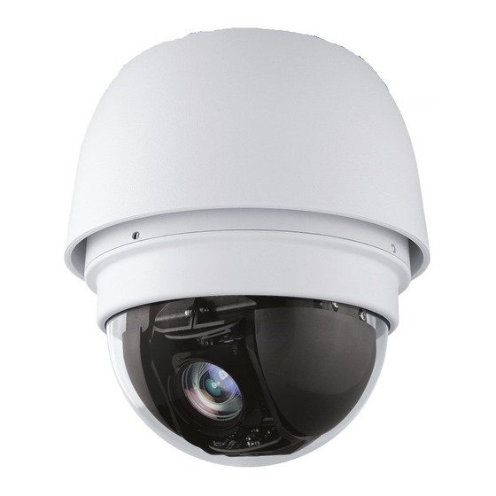
- Page 1 Outdoor Speed Dome Camera Installation Manual Camera Accessories CM-512 CA-510G CA-510PML CA-510W CA-510PMS CA-510C CA-510PA25 CA-510P25 CA-510PA50 CA-510P50 www.openeye.net...
- Page 3 The information in this publication is provided “as is” without warranty of any kind. The entire risk arising out of the use of this information remains with recipient. In no event shall OPENEYE be liable for any direct, consequential, incidental, special, punitive, or other damages whatsoever...
-
Page 4: Important Safeguards
Important Safeguards Read Instructions Read all of the safety and operating instructions before using the product. Retain Instructions Save these instructions for future reference. Attachments / Accessories Do not use attachments or accessories unless recommended by the appliance manufacturer as they may cause hazards, damage product and void warranty. Installation Do not place or mount this product in or on an unstable or improperly supported location. - Page 5 Installation and Storage • Do not install the camera in areas of extreme temperatures in excess of the allowable range. ( -58°F ~ 122°F / -50°C ~ 50°C) • Avoid installing in humid or dusty places. The relative humidity must be below 90%.
- Page 6 Warning DANGEROUS HIGH VOLTAGES ARE PRESENT INSIDE THE ENCLOSURE. DO NOT OPEN THE CABINET. REFER SERVICING TO QUALIFIED PERSONNEL ONLY. Caution C A U T I O N RISK OF ELECTRIC SHOCK DO NOT OPEN CAUTION: TO REDUCE THE RISK OF ELECTRIC SHOCK, DO NOT REMOVE COVER (OR BACK).
-
Page 7: Standard Warranty
OpenEye will warrant all otherwise out-of-warranty replacement parts and repairs for 90 days from the date of OpenEye shipment. The above warranty is the sole warranty made by OpenEye and is in lieu of all other warranties by OpenEye express and implied, including without limitation the warranties of merchant ability and fitness for a particular purpose. -
Page 8: Table Of Contents
TABLE OF CONTENTS Introduction ........................... 10 Overview ............................ 10 General Operation Requirements ....................10 System Configuration ......................10 Getting Started ..........................12 Box Contents ..........................12 Dome Setup and Cable Connection ................... 13 Preparations for Dome Setup ....................13 Switch Definitions ......................15 RS-485 Switch Setting ...................... - Page 9 NOTES: 31515AB...
-
Page 10: Introduction
GENERAL OPERATION REQUIREMENTS A minimum of one control device is required for operation, such as a control keyboard, or a recorder. The CM-512 includes a built-in receiver that decodes commands from a control device. Connect dome cameras to other devices, as shown in the diagram below, to complete a video surveillance system. - Page 11 NOTES: 31515AB...
-
Page 12: Getting Started
Before proceeding, please check that the box contains the items listed here. If any item is missing or has defects, DO NOT install or operate the product. Contact your dealer for assistance. CM-512 Camera Optical Cover Screws (x4) Quick Start Guide... -
Page 13: Dome Setup And Cable Connection
DOME SETUP AND CABLE CONNECTION Before installing or connecting the dome camera, please refer to this section and complete preparations for dome setup and all switch settings. Preparations for Dome Setup The following installation procedure is for the outdoor dome equipped with the sunshield housing. Please follow the steps below to complete dome housing installation. - Page 14 Using both hands, gently press the dome cover. Do not press the cover from the dome. Use screws to affix the dome cover to the body. Set the switches located on the bottom of the camera. Refer to the user manual for information about various switch settings.
-
Page 15: Switch Definitions
Dome Camera Setup Before connecting the dome camera to other CCTV devices, please complete the camera ID and communication switch settings. These switches are located on the bottom of the dome camera. Switch Definitions Alarm inputs RS485 connector Camera ID switch BNC output Protocol switch ISP connector... -
Page 16: Rs-485 Switch Setting
RS-485 Switch Setting Switch RS-485 Setting Termination Line Lock System Initialization Reserved RS-485 is the interface that the dome RS-485 Setting camera uses to communicate with its control device; for this reason, the RS- Half-duplex Full -duplex 485 setup of the dome and the control device must be the same. -
Page 17: Dome Control Protocol Setting
Dome Control Protocol Setting Define the protocol you are going to use based on the devices of your surveillance system. Generally, use one protocol even if the devices are provided by different manufacturers. Use the switch to set your dome control protocol and the baud rate. Refer to the table below and turn the arrow to choose a protocol for your speed dome. -
Page 18: Power Connector
AC IN - Apply Alarm I/O The CM-512 supports 4 digital alarm inputs and 2 digital alarm outputs. Please make sure the alarm connections are properly wired before starting to configure alarm-related settings. Please refer to the pin definition table for alarm system wiring. -
Page 19: Rs-485 Connector Definition
The dome camera uses the RS-485 interface to communicate with a connected control device. Connect a control keyboard to the speed dome using the terminal block. OpenEye recommends using CAT 5 cables for RS-485 communication with a maximum length of 4000 feet (1219 meters) for 24-gauge wire. If the total cable length exceeds 4000 feet, use a repeater to maintain the signals. -
Page 20: Grounding Recommendation
Grounding Recommendation The GND wire must be directly connected to the middle pin of the AC24V power connector. Failure to connect the ground can cause damage and failure of the camera and may void the warranty. If the connection of the GND wire causes video noise, use a video isolator. This is only necessary in some situations. -
Page 21: Dome Dimensions
DOME DIMENSIONS The dome dimensions are Ø172 x 228.71mm (6.77 x 9.0 inches) and Ø191.97 x 282.11mm (7.5 x 11.1 inches) with the sunshield. 31515AB... -
Page 22: Optional Accessories
OPTIONAL ACCESSORIES Dome Camera Accessories Transparent/Smoke Cover Part Number: CA-510-DT Mounting Accessories Wall Mount Bracket (w/ Anti Drop) Part Number: CA-510W Long Wall Mount Bracket (w/ Anti Drop) Part Number: CA-510WL 50 cm Pole Part Number: CA-510P50 25 cm Pole Part Number: CA-510P25 Corner Mounting Plate Part Number: CA-510C... -
Page 23: Ceiling Mounting With Pole
Ceiling Mounting with Pole The pole is available in two lengths: 25 cm and 30 cm. Items Needed: Tools Needed: • • Dome Camera Drill • • Ceiling Pole Accessory Screwdriver • Waterproof Gasket (supplied) • Screws and Anchors appropriate for the mounting surface (not supplied) Installation Steps: Note... -
Page 24: Wall Mounting With Wall Mount Bracket
Wall Mounting with Wall Mount Bracket Items Needed: Tools Needed: • • Dome Camera Drill • • Wall Mount Bracket or Long Screwdriver Wall Mount Bracket • Waterproof Gasket (supplied) • Screws and Anchors appropriate for the mounting surface (not supplied) Installation: Cut a cable access hole on the wall. - Page 25 Attach the wall mount bracket to the wall with the appropriate screws and screw anchors (not provided). Attach the waterproof gasket to the wall mount bracket. Thread the cables through the top holder and attach the dome to the wall mount bracket with the supplied screws and washers.
-
Page 26: Wall Mounting With Corner Mount
Wall Mounting with Corner Mount The corner mount must be used in conjunction with the wall mount bracket. Items Needed: Tools Needed: • • Dome Camera Drill • • Wall Mount Bracket Accessory Screwdriver • Corner Mounting Plate • Waterproof Gasket (supplied) •... -
Page 27: Pole Mounting
Pole Mounting The dome can be mounted on a pole with the small or large direct mounting assembly and a wall mount bracket. Items Needed: Tools Needed: • • Dome Camera Stainless Steel Strap Cutter • Screwdriver Wall Mount Bracket Accessory •... -
Page 28: Specifications
SPECIFICATIONS CAMERA SPECIFICATIONS Model CM-512 Image Sensor 1/4” Sony CCD IP Rating IP66 Type / Format NTCS Wide Dynamic Range Minimum Illumination 0.4 Lux (B/W) / 1 Lux (Color) (DSS OFF) @ 50IRE Minimum Illumination 0.2 Lux (B/W) / 0.6 Lux (Color) (DSS OFF) -
Page 29: Ptz Specifications
Dimensions Ø7.5" (190.5mm) x H: 11.1" (282mm) Housing / Dome Cover White / Clear PTZ SPECIFICATIONS Model CM-512 Outdoor Speed Dome Built-in Protocol Optix III, Pelco D & P, VCL Optical Zoom Pan/Tilt Range 360° Endless / -10° ~ 190°... - Page 31 © 2012 OpenEye All rights reserved. No part of this publication may be reproduced by any means without written permission from OpenEye. The information in this publication is believed to be accurate in all respects. However, OpenEye cannot assume responsibility for any consequences resulting from the use thereof.
Need help?
Do you have a question about the CM-512 and is the answer not in the manual?
Questions and answers