
Subscribe to Our Youtube Channel
Related Manuals for OpenEye CM-L812


Summary of Contents for OpenEye CM-L812
- Page 1 36x Outdoor IP PTZ Dome User Manual Camera Accessories CM-L812 CA-510G CA-510PML CA-510W CA-510PMS CA-510C CA-510PA25 CA-510P25 CA-510PA50 CA-510P50 www.openeye.net...
- Page 3 No part of this documentation may be reproduced in any means, electronic or mechanical, for any purpose, except as expressed in the Software License Agreement. OpenEye shall not be liable for technical or editorial errors or omissions contained herein. The information in this document is subject to change without notice.
-
Page 4: Important Safeguards
Important Safeguards Read Instructions Read all of the safety and operating instructions before using the product. Retain Instructions Save these instructions for future reference. Attachments / Accessories Do not use attachments or accessories unless recommended by the appliance manufacturer as they may cause hazards, damage product and void warranty. - Page 5 Installation and Storage • Install electricity wiring carefully. Please note that input electricity to the unit is at tolerance of DC 12V/AC 24V ± 10%. The camera is capable of surge protection; ensure AC power model unit is grounded appropriately against damage by heavy current or electric shock. •...
- Page 6 Warning DANGEROUS HIGH VOLTAGES ARE PRESENT INSIDE THE ENCLOSURE. DO NOT OPEN THE CABINET. REFER SERVICING TO QUALIFIED PERSONNEL ONLY. Caution C A U T I O N RISK OF ELECTRIC SHOCK DO NOT OPEN CAUTION: TO REDUCE THE RISK OF ELECTRIC SHOCK, DO NOT REMOVE COVER (OR BACK).
-
Page 7: Standard Warranty
OpenEye will warrant all otherwise out of warranty replacement parts and repairs for 90 days from the date of OpenEye shipment. The above warranty is the sole warranty made by OpenEye and is in lieu of all other warranties by OpenEye express and implied, including without limitation the warranties of merchantability and fitness for a particular purpose. -
Page 8: Table Of Contents
Wall Mounting with Wall Mount Bracket ................23 Wall Mounting with Corner Mount ..................25 Pole Mounting ........................26 Locate Camera ..........................27 OpenEye Network Camera manager ..................27 Installation ..........................27 Starting Network Camera Manager ..................27 Device Addressing ....................... 28 Finding Network Devices .................... - Page 9 Viewer Software ........................32 Viewer Tabs ......................... 32 Home ........................... 33 System ..........................36 System ..........................36 Security ........................... 38 Admin Password ......................38 Add User ........................39 Delete User ........................ 39 Edit User ........................39 Network........................... 40 Get IP address automatically (DHCP) ................ 40 Use Fixed IP Address ....................
- Page 10 Video OCX Protocol ......................68 Multicast Mode ......................68 Frame Rate Control ......................69 Audio ..........................70 Transmission Mode....................70 Server Gain Settings ....................70 Bit Rate ........................71 PTZ Settings ..........................72 Preset ..........................72 Preset Setting ......................... 72 Preset Go ........................
-
Page 11: Introduction
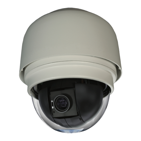
INTRODUCTION OVERVIEW With an IP66 rating, the CM-L812 Outdoor PTZ IP Camera is suitable for outdoor installations. The CM-L812 IP camera can transmit video at H.264 and MJPEG, dual streaming both codecs at D1 at 30IPS. The camera’s IR cut filter and wide dynamic rage imaging make it perfect for installations with difficult lighting conditions. -
Page 12: Getting Started
GETTING STARTED CAMERA CONTENTS Before proceeding, please check that the box contains the items listed here. If any item is missing or has defects, DO NOT install or operate the product and contact your dealer for assistance. Dome Body Optical Cover Screws Security Torx Tool Waterproof Gasket... -
Page 13: Dome Setup And Cable Connection
DOME SETUP AND CABLE CONNECTION Before installing or connecting the dome camera, please refer to this section and complete preparations for dome setup and all switch settings. Preparations for Dome Setup The following installation procedure is for the outdoor dome equipped with the sunshield housing. - Page 14 Remove the protective cover and PE sheet. Apply some lubricant on the cover’s waterproof gasket. This helps make the installation process smoother. Attach the dome cover to the camera body. Note that the tiny protrusion on the cover must align with one of the four holes on the camera body.
- Page 15 Using both hands, gently press the dome cover using both hands. DO NOT press the dome itself as this may cause damage to the dome or camera. To secure the dome cover to the camera body, use a screwdriver to extend the screws outward.
-
Page 16: Dome Camera Setup
Dome Camera Setup Switch Definition Please refer to the following figure for switch location and definitions. Alarm input/output connections Reboot Power connection Audio connection RJ-45 connector SD card Note Do not change the settings on the camera’s Communication Switch. Leave the switch at the factory default settings. -
Page 17: Dome Cable Definition And Requirements
For operation, the IP dome camera requires a network cable to carry the video signals to the remote viewing site and a power cable to power the dome. Cable Requirements For operation, the CM-L812 IP camera requires AC 24V power to the dome. Power Wire Length Specifications Wire... -
Page 18: Power Connection
Note Be careful not to pull the cables improperly during installation. OpenEye suggests that you fasten the cables after installation is complete. Grounding Recommendation The GND (ground) wire must be directly connected to the middle pin of the AC24V power connector. -
Page 19: 12-Pin Alarm Input/Output Connection
12-Pin Alarm Input/Output Connection Using the 12-pin connector, installers can connect 4 digital alarm inputs and 2 digital alarm outputs. The alarm pins are serviceable for connecting alarm input and output devices such as sensors, sirens, or flashing lights to the surveillance system. -
Page 20: Dome Installation
DOME INSTALLATION OVERVIEW Depending on your installation environment, the dome can be installed on the ceiling, on a wall, or a pole. The following section illustrates installation methods and procedures for installing the dome and mounting accessories. DOME DIMENSIONS The dome dimensions are Ø172 x 228.71mm (6.77 x 9.0 inches) and Ø191.97 x 282.11mm (7.5 x 11.1 inches) with the sunshield. -
Page 21: Optional Accessories
OPTIONAL ACCESSORIES Dome Camera Accessories Transparent/Smoke Cover – Part Number: CA-510-DT Mounting Accessories Wall Mount Bracket (w/ Anti Drop) – Part Number: CA-510W Long Wall Mount Bracket (w/ Anti Drop) – Part Number: CA-510WL 50 cm Pole – Part Number: CA-510P50 25 cm Pole –... -
Page 22: Ceiling Mounting With Pole
Ceiling Mounting with Pole The pole is available in two lengths: 25 cm and 30 cm. Items Needed Tools Needed Dome Camera Drill Ceiling Pole Accessory Screwdriver Waterproof Gasket (supplied) Screws and anchors appropriate for the mounting surface (not supplied Installation Steps: Note Ensure that the ceiling can support the weight of the dome camera and... -
Page 23: Wall Mounting With Wall Mount Bracket
Attach the dome to the top holder and secure them with the supplied screw. Wall Mounting with Wall Mount Bracket Items Needed Tools Needed Dome Camera Drill Wall Mount Bracket or long wall mount Screwdriver bracket Waterproof Gasket (supplied) Screws and anchors appropriate for the mounting surface (not supplied) Installation: Cut a cable access hole on the wall. - Page 24 Attach the wall mount bracket to the wall with the appropriate screws and screw anchors (not provided). Attach the waterproof gasket to the wall mount bracket. Thread the cables through the top holder and attach the dome to the wall mount bracket with the supplied screws and washers.
-
Page 25: Wall Mounting With Corner Mount
Wall Mounting with Corner Mount The corner mount must be used in conjunction with the wall mount bracket. Items Needed Tools Needed Dome Camera Screws and anchors appropriate for the mounting surface (not supplied) Wall Mount Bracket Accessory Corner Mounting Plate Waterproof Gasket (supplied) Installation: Cut a cable access hole on the wall. -
Page 26: Pole Mounting
Pole Mounting The dome can be mounted on a pole with the small or large direct mounting accessory and a wall mount bracket. Items Needed Tools Needed Dome Camera Stainless Steel Strap Cutter Wall Mount Bracket Accessory Screwdriver Small/Large Pole Mount Accessory Stainless Steel Straps Waterproof Gasket (supplied) Installation Steps:... -
Page 27: Locate Camera
LOCATE CAMERA OPENEYE NETWORK CAMERA MANAGER Use the included Network Camera Manager software to easily find your network cameras for initial setup. The OpenEye IP Finder software is included on the CD with all OpenEye IP devices. Installation You can install Network Camera Manager on any personal computer (PC) or laptop using the software CD included with your OpenEye IP camera or by downloading the program from openeye.net. -
Page 28: Device Addressing
Device Addressing The functions on the Device Addressing tab allow you to find, configure, and view network cameras. Finding Network Devices 13. Click Find Devices on the Device Addressing tab. 14. To narrow your search by Camera Model, Project, or Camera Name, select your desired criteria from the appropriate lists. -
Page 29: Setup & Configuration
Log in to the camera with the appropriate User Name and Password. Note The default User name is Admin and the default Password is1234. The username and password are case sensitive. OpenEye recommends you change the Admin password for security reasons. Administrator/User Privileges The Administrator account has the authority to configure the IP camera and authorize users’... -
Page 30: Connecting A Stream
OpenEye IP cameras using third party software like VLC media player (http://www.videolan.org). To connect the camera you may need to provide the stream URL. All OpenEye IP cameras are capable of delivering two RTSP streams, as well as streaming MJPEG over HTTP. -
Page 31: Connecting Over The Internet
OpenEye) as the default streaming option. However, RTSP is not suitable for transmission between two locations that are behind different routers. In this case, the client (for example, the OpenEye HVR or NVR server software) connects to the camera, then requests a stream. The... -
Page 32: Viewer Software
VIEWER SOFTWARE To access the setup menu, you need to install the viewer software on your PC or DVR. The viewer software will install automatically the first time you connect to the camera. If your internet browser doesn’t install the viewer software, check the security settings or ActiveX controls and plug-in settings. -
Page 33: Home
Home Screen Size Adjustment Image display size can be adjusted to x1/2 and full screen via the related buttons. To switch between the normal view mode and full screen view mode, users can also move the cursor to the live video pane and right-clink to display the screen options. - Page 34 Listen The Speaker function allows the local site to listen to audio from the remote site (camera location). This function is only available if the local site has connected speakers, the remote site has a connected microphone, and the local user has been granted access.
- Page 35 Pan/Tilt Control To implement pan/tilt control, move the cursor to the live video pane and drag the pointer in the desired direction. Zoom Adjustment Click on the wide/tele buttons to control zoom in/out. Or move the cursor to the zoom adjustment bar and click the desired position to change the room ratio. Or you can zoom in/out by first moving the cursor to the live video pane and rotating the mouse wheel.
-
Page 36: System
System Note The System tab is only accessible by the Administrator. System Host Name The Host Name is used to identify the camera on your system. If camera based Motion Detection is enabled and is set to send alarm message by Mail/FTP, the host name entered here will display in the alarm message. - Page 37 Enable Daylight Savings Time Select to enable daylight savings time, then select the offset, start date and end date. In North America the typical offset is one hour (01:00:00); the start is the second Sunday in March at 2AM (02:00:00), and the end is the first Sunday in November at 2AM (02:00:00).
-
Page 38: Security
Security Admin Password To change the administrator password, type a new password in the Admin Password box and confirm below. Note The maximum length of the password is 14 characters. The following characters are valid: A-Z, a-z, 0-9, !#$%&’-.@^_~. -
Page 39: Add User
Add User The user name and passwords are limited to 16 characters. There is a maximum of twenty user accounts Type the new User name and Password Select the appropriate check boxes to give the user Camera Control, Talk and Listen permissions. I/O Access –... -
Page 40: Network
Each camera has a unique Media Access Control (MAC) address, which can be used to identify the camera on the network. Record the IP Camera’s MAC address, which can be found using the OpenEye IP Finder application and on the label of the camera, for identification in the future. - Page 41 When using static IP address to log in to the IP Camera, you can access it either through OpenEye IP Finder software or type the IP address directly in the address bar of your Internet Explorer. General • IP address – The IP Address is necessary for network identification.
-
Page 42: Qos (Quality Of Service)
QoS (Quality of Service) Quality of Service allows you to prioritize network traffic services of the camera’s functions. The QoS function utilizes the Differentiated Services prioritized using Codepoint values (DSCP). Note Routers and switches on the network must be QoS or DSCP capable, and have these settings enabled for this function to operate on your network. -
Page 43: Upnp (Universal Plug And Play)
UPnP (Universal Plug and Play) • Enable UPnP: When enabled the camera will appear in My Network Places on Windows computers running UPnP on the same network. • Enable UPnP Port Forwarding: When enabled the camera will attempt to open the web server port on the router automatically. •... -
Page 44: Ddns
DDNS DDNS (Dynamic Domain Name Service) is a service that allows a connection to an IP address using a hostname (URL) address instead of a numeric IP address. Most Internet Service Providers use Dynamic IP Addressing that frequently changes the public IP address of your internet connection; this means when connecting to the camera over the internet you need to know if your IP address has changed. -
Page 45: Mail
Mail The camera can send an e-mail via Simple Mail Transfer Protocol (SMTP) when motion is detected or when the sensor input is activated. SMTP is a protocol for sending e-mail messages between servers. SMTP is a relatively simple, text- based protocol, where one or more recipients of a message are specified and the message text is transferred. -
Page 46: Ftp
The camera can send alarm messages to a specific File Transfer Protocol (FTP) site when motion is detected or when the sensor input is activated. You can assign alarm messages to up to two FTP sites. • Enter the FTP details, which include server, server port, user name, password and remote folder, in the appropriate boxes and click Save when finished. -
Page 47: Http
HTTP The camera can send alarm messages to a specific Hypertext Transfer Protocol (HTTP) site when motion is detected or when the sensor input is activated. You can assign alarm messages to up to two HTTP sites. • Enter the HTTP details, which include server, user name and password, in the appropriate boxes and click Save when finished. -
Page 48: Application
Application The CM-816 supports 4 digital alarm inputs and 2 digital alarm outputs. Make sure the alarm connections are properly wired before starting to configure alarm related settings on the Application screen. Refer to the pin definition table below for alarm system wiring. Definition Alarm OUT NO 1 Alarm OUT NC 1... -
Page 49: Alarm Pin Selection
Alarm Pin Selection Select an alarm pin from the Alarm Pin Selection box and click Edit to start alarm programming. 31648AB... -
Page 50: Alarm Pin Status Settings
Alarm Pin Status Settings Alarm Setting • Alarm Switch – Enable or disable the alarm function. • Alarm Type – Select an alarm type (Normal Close or Normal Open) that corresponds with the alarm application. Trigger Action (Multi-Option) Specify alarm actions that will take place when the alarm is triggered. •... - Page 51 • PTZ Function – Assign a PTZ function (Preset, Tour, Auto Scan or Pattern) for the camera to perform when this alarm is activated. Note If Preset is selected, you will be prompted to enter a Dwell Time (1~256). This is the time in seconds that the camera will remain at that Preset location, and then it will return to the location that it was pointing at the time the alarm occurred.
-
Page 52: Motion Detection
Motion Detection Motion Detection allows the camera to detect motion and trigger alarms when motion in the detected area exceeds the determined sensitivity threshold value. On the Motion Detection page, there is a motion detection window (red box) displayed on the Live View Pane. The Motion Detection window defines the motion detection area. - Page 53 When motion detection is activated, the Motion pop-up window will open. When motion is detected, the signals will be displayed on the Motion window as shown below Motion Detection Turn motion detection on or off. The default setting is Off. Motion Detection Setting In the Motion window the red line provides a motion detection threshold indication;...
- Page 54 Triggered Action Once motion detection has been fine tuned, the Triggered Action can be configured if you want the camera to take one of these actions upon sensing motion. • Enable Alarm Output – Select to trigger the alarm output on the camera on motion detection.
-
Page 55: Storage Management
Storage Management Storage Management allows you to view information about an inserted Micro SD/SDHC card (up to 32GB), format the SD card, adjust cleanup settings, and download or delete files stored on the SD card. Device Information – When a compatible Micro SD/SDHC card is inserted into the camera, information about the card will be displayed in this section. - Page 56 Disk Cleanup Setting – An automatic cleanup can be configured so that once the available storage on the Micro SD/SDHC card reaches a percentage of use, older items will be removed. To enable Disk Cleanup: Select Enable automatic disk cleanup. Enter a percentage of use threshold needed to trigger the cleanup.
-
Page 57: Recording
Recording The recording schedule allows you to set up scheduled recording to a local Micro SD/SDHC card. Activating Micro SD/SDHC Card Recording To set up continuous micro SD/SDHC card recording: Select Always to continually record until the card is full. To set the camera to overwrite old data, see the instructions for Disk Cleanup Setting earlier in this section. -
Page 58: Snapshot
Snapshot The CM-816 camera supports JPEG snapshot function. You can specify a storage location for the snapshots. The default setting is: C:\. Note If you are using Windows Vista or 7, you will need to change the Snapshot location. Windows UAC does not allow internet programs to write directly to C:\ for security reasons. -
Page 59: Information
Information The Information page to contains the System Log, User Information, and Parameter List. System Log Click System Log to view the system log file. The content of the file provides useful information about configuration and connections. 31648AB... -
Page 60: View User Information
View User Information The Administrator can view each user’s login information and privileges on the View User Information page All the users in the network are listed under User information. The example below shows that the Admin password is 1234. View User Privilege Select a user account from the list and click get user privacy to view the permissions for the user account. -
Page 61: Parameter List
Parameter List Click Parameter List to view the system parameter settings. 31648AB... -
Page 62: Software Upgrade
Programs. Locate the Camera Viewer software on the Currently installed programs list and click Remove to uninstall the previous software version. Open the internet browser again and log in to the CM-L812. The system will automatically download the new version of the Camera Viewer software. -
Page 63: Maintenance
Maintenance On the Maintenance page you can export the cameras current configuration, or import the configuration for a camera. Use the factory default page to reset the IP Camera to factory default settings if necessary. Note Do not import configuration files from different models of cameras. Set Default –To reset the IP camera to the factory default settings, including the default IP address, click Set Default. -
Page 64: Video And Audio Streaming Settings
Video and Audio Streaming Settings On the Streaming tab, the Administrator can configure specific video resolution, video compression mode, video protocol, audio transmission mode, etc. Video Format Select the desired video resolution for the camera on the Video Format page. The recorder will record video based on the resolution selected here. -
Page 65: Video Resolution
Video Resolution The camera provides multiple codec options under video resolution (two single streaming options and two sets of dual, triple, and quad streaming options): • MJPEG + H.264 • H.264 + H.264 • H.264 + H.264 + H.264 • H.264 + H.264 + MJPEG •... -
Page 66: Video Rotate Type
Video Rotate Type You can change the orientation of the video output if necessary. Normal Video – This is the default rotation designed for a normal setup with the camera mounted with the dome facing down. Flip Video – This option will vertically flip the video image (without the intervention of another device this may cause the reversal of perceived left and right when viewing the image). -
Page 67: Video Compression
Video Compression You can select an MJPEG/H.264 compression mode on the video compression page appropriate for your application. You can also select to display compression information on the Home page. MJPEG Compression settings include: • high compression, low bit rate, low quality •... -
Page 68: Video Ocx Protocol
Video OCX Protocol On the Video OCX protocol page, you can select different protocols for streaming media over the network. In the case of multicast networking, you can select the Multicast mode. Video OCX protocol setting options include: RTP over UDP RTSP over HTTP RTP over RTSP (TCP) MJPEG over HTTP... -
Page 69: Frame Rate Control
Frame Rate Control Setting the camera to transmit fewer frames can save bandwidth. Each of the MJPEG and H.264 streams can have a separate frame rate setting from 1 to 30 frames per second. Note Higher frame rate will increase video smoothness, as well as file size and bandwidth usage. -
Page 70: Audio
Audio On the audio page, the Administrator can select an audio transmission mode and audio bit rate. Note Audio monitoring and recording laws vary from location to location. It is highly recommended that you consult your local, state, and federal laws to verify that you are in compliance before implementing audio recording. -
Page 71: Bit Rate
Bit Rate Selectable audio transmission bit rate include: 16 kbps (G.726) 40 kbps (G.726) 24 kbps (G.726) uLAW (G.711) 32 kbps (G.726) ALAW (G.711) Both uLAW and ALAW signify 64 kbps but in different compression formats. Higher bit rate will provide higher audio quality and require more bandwidth. 31648AB... -
Page 72: Ptz Settings
PTZ SETTINGS Use the PTZ tab to program Presets, Patterns, Auto Scans and Tours via PTZ controls. Additionally, various camera settings including Auto Exposure (AE), White Balance (WB), Back Light Compensation (BLC), Sharpness, Exposure Compensation, etc. also can be set here. Preset Note Up to 256 Presets can be programmed for the camera. -
Page 73: Preset Go
Preset Go To move the camera view to a specified Preset position: • Select the Preset Point from the list under Preset Go. The camera will move to the target position. Pattern Note The camera supports up to eight patterns. Pattern Setting To create a Pattern: Select a path number from the Pattern Path list. -
Page 74: Pattern Run
Pattern Run Select the specified Pattern from the Pattern Path list and click Run. To view the camera in full screen mode, move the pointer onto the live view pane, right-click and select Fullscreen. To stop running a Pattern, move the cursor to the live view pane and use the PTZ controls to move the camera in any direction. -
Page 75: Auto Scan Setting
Auto Scan Setting To create an Auto Scan path: Select a path number from the Auto Scan Path list. Move the pointerr to the live view pane, and move the camera to a desired view as the Start Point of an Auto Scan Path. Click the “Set”... -
Page 76: Tour
Tour The camera supports up to eight Tours; each Tour supports up to 64 Presets. Note Before setting this function, you must pre-define at least two Presets. -
Page 77: Tour Set
Tour Set On the Tour screen, click Edit to open the Tour Set options. Select the number of the new tour from the Tour Line list at the top of the screen. Select each Preset to add to the tour. Enter the Dwell Time (0~127 seconds) and Speed (0~14) for each Preset. -
Page 78: Home
Home Set up the Home function to ensure constant monitoring. If the camera idles for a period of time, the selected function will be activated automatically and return the camera to the home function setting. The Home function allows constant and accurate monitoring to prevent the camera from idling or missing events. -
Page 79: Tilt Range
Tilt Range The camera’s Tilt Range is adjustable. The minimum tilt angle can be set between -10° and 10°. The maximum tilt angle can be set between 170° and 190°. • Enter the desired min. and max. tilt angle into the corresponding fields respectively and click Set to save the tilt angle settings. -
Page 80: Privacy Mask Settings
The Privacy Mask function helps avoid any intrusive monitoring. When you create a mask, OpenEye recommends that you set it at least twice as big (height and width) as the masked object. The camera will assume the center of the selected view as a starting point. -
Page 81: Mask Setting
Mask Setting Activate/Disable Privacy Mask Function Set to On/Off to activate or disable the Privacy Mask function and click Set. Activate/Disable Transparency Mask Set the transparency of the Privacy Mask if necessary. Color Setting Select the desired color from the Color list for the specified Privacy Mask and click Set. -
Page 82: Camera - Exposure
Camera — Exposure On the Exposure screen you can select Full Auto mode or adjust the parameters manually for optimized video output in accordance with the operating environment. Shutter Priority When Shutter Priority is selected the shutter speed takes control of exposure. Shutter speed range is 1/60 ~ 1/10000. -
Page 83: Camera - White Balance
Camera — White Balance A camera uses a reference color temperature, which is a way of measuring the quality of a light source, to calculate all the other colors. The unit for measuring this ratio is degrees Kelvin (K). You can select the White Balance Control according to the operating environment. - Page 84 Auto Mode In Auto mode, white balance works within its color temperature range and calculates the best-fit white balance. Indoor/outdoor Mode Select for indoor or outdoor mode. ATW Mode (Auto Tracing White Balance) The Dome Camera takes out the signals in a screen in the range from 2000 K to 10000 K.
-
Page 85: Camera - Misc1
Camera — Misc1 In Camera—Misc1, you can set various camera parameters including Backlight Compensation, Sharpness, Exposures Compensation, Image Freeze, Image Flip, Digital Zoom, Speed by Zoom and ICR Function. • BLC – Activate or disable the Backlight Compensation function (On/Off). •... - Page 86 • Flip – Track an object continuously when it passes under the camera by setting Flip to Mechanical (M.E.) mode or Digital Flip (Image) mode. • M.E. Mode – M.E. is a standard mechanical operation. As the camera tilts to the maximum angle, it will pan 180°, and then continue tilting to keep tracking objects.
-
Page 87: Camera - Misc2
Camera — Misc2 In Camera—Misc2, you can set up various functions such Auto Calibration, Wide Dynamic Range, 2D Noise Reduction and TV System. • WDR – Wide Dynamic Range is especially effective in an environment with extreme contrast. • Auto Calibration – Auto Calibration function automatically calibrates the camera when the deviation of dome pivot is detected. -
Page 88: Camera - Default
Camera — Default Click Set Default to reset the camera back to factory default settings. LOGOUT Click the Logout tab to open the login window and log in with a different user name and password. -
Page 89: Specifications
SPECIFICATIONS CAMERA SPECIFICATIONS Model CM-L812 Image Sensor 1/4” Sony CCD IP Rating IP66 Type / Format H.264 / MJPEG Wide Dynamic Range 0.6 Lux (Color) / 0.2 Lux (B&W) (@ 30IRE) Minimum Illumination 1 Lux (Color) / 0.4 Lux (B&W) (@ 50IRE) -
Page 90: Ptz Specifications
PTZ SPECIFICATIONS Optical Zoom Pan/Tilt Range 360° Endless / -10° ~ 190° Presets Preset Accuracy ± 0.225° Preset Speed 5° ~ 400°/sec. Pattern Tour (Group) Auto Scan Privacy Mask Home Function Preset, Pattern, Tour, Autoscan Auto Flip Image / Mechanical / Off Digital Slow Shutter On / Off Focus Mode... - Page 91 © 2013 OpenEye All rights reserved. No part of this publication may be reproduced by any means without written permission from OpenEye. The information in this publication is believed to be accurate in all respects. However, OpenEye cannot assume responsibility for any consequences resulting from the use thereof.
Need help?
Do you have a question about the CM-L812 and is the answer not in the manual?
Questions and answers