
Related Manuals for OpenEye CM-814


Summary of Contents for OpenEye CM-814
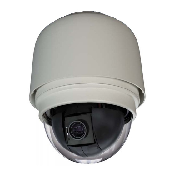
- Page 1 Outdoor Speed Dome Camera User Manual Camera Accessories CM-814 CA-510G CA-510PML CA-510W CA-510PMS CA-510C CA-510PA25 CA-510P25 CA-510PA50 CA-510P50 www.openeye.net...
- Page 3 No part of this documentation may be reproduced in any means, electronic or mechanical, for any purpose, except as expressed in the Software License Agreement. OpenEye shall not be liable for technical or editorial errors or omissions contained herein. The information in this document is subject to change without notice.
-
Page 4: Important Safeguards
Important Safeguards Read Instructions Read all of the safety and operating instructions before using the product. Retain Instructions Save these instructions for future reference. Attachments / Accessories Do not use attachments or accessories unless recommended by the appliance manufacturer as they may cause hazards, damage product and void warranty. Installation Do not place or mount this product in or on an unstable or improperly supported location. - Page 5 Installation and Storage • Install electricity wiring carefully. Please note that input electricity to the unit is at tolerance of DC 12V/AC 24V ± 10%. The camera is capable of surge protection; ensure AC power model unit is grounded appropriately against damage by heavy current or electric shock.
- Page 6 Warning DANGEROUS HIGH VOLTAGES ARE PRESENT INSIDE THE ENCLOSURE. DO NOT OPEN THE CABINET. REFER SERVICING TO QUALIFIED PERSONNEL ONLY. Caution C A U T I O N RISK OF ELECTRIC SHOCK DO NOT OPEN CAUTION: TO REDUCE THE RISK OF ELECTRIC SHOCK, DO NOT REMOVE COVER (OR BACK).
-
Page 7: Standard Warranty
OpenEye will warrant all otherwise out of warranty replacement parts and repairs for 90 days from the date of OpenEye shipment. The above warranty is the sole warranty made by OpenEye and is in lieu of all other warranties by OpenEye express and implied, including without limitation the warranties of merchantability and fitness for a particular purpose. -
Page 8: Table Of Contents
Ceiling Mounting with Pole ................28 Wall Mounting with Wall Mount Bracket ............29 Wall Mounting with Corner Mount ..............31 Pole Mounting ....................32 Camera Finder .................. 33 OpenEye IP Finder ....................33... - Page 9 Finding IP Cameras ..................33 Default Username and Password ..............33 Changing the Network Type ................34 Setup & Configuration ..............34 Connecting to the Camera ..................34 Administrator/User Privileges ................34 Viewer Software ....................35 ...
- Page 10 Upgrading the Camera Viewer Software ............. 56 Video and Audio Streaming Settings ..............57 Video Resolution and Video Deinterlacing Function ........57 Video Compression ..................58 Video OCX Protocol ..................59 Multicast Mode ..................... 59 ...
- Page 11 Specifications .................. 78 Camera Specifications ..................78 PTZ Specifications ....................79 IP Specifications ....................79 30101AB...
-
Page 12: Introduction
INTRODUCTION OVERVIEW With an IP66 rating, the CM-814 Outdoor PTZ IP Camera is suitable for outdoor installations. The CM-814 IP camera can transmit video at H.264 and MJPEG, dual streaming both codecs at D1 at 30IPS. The camera’s IR cut filter and wide dynamic rage imaging make it perfect for installations with difficult lighting conditions. -
Page 13: General Operation Requirements
GENERAL OPERATION REQUIREMENTS A minimum of one control device is required for operation, such as a control keyboard, or a DVR. The integrated high speed dome camera contains a built-in receiver that decodes commands from a control device. Connect dome cameras to other devices, as shown in the diagram below, to complete a video surveillance system. -
Page 14: Getting Started
GETTING STARTED CAMERA CONTENTS Before proceeding, please check that the box contains the items listed here. If any item is missing or has defects, DO NOT install or operate the product and contact your dealer for assistance. All-in-one Data Cable for power supply, video and audio and alarm. -
Page 15: Dome Setup And Cable Connection
DOME SETUP AND CABLE CONNECTION Before installing or connecting the dome camera, please refer to this section and complete preparations for dome setup and all switch settings. Preparations for Dome Setup The following installation procedure is for the outdoor dome equipped with the sunshield housing. - Page 16 Remove the protective cover and PE sheet. Attach the dome cover to the camera body. Before doing that, apply some lubricant on the cover’s waterproof gasket. This helps make the installation process smoother. Note that the tiny protrusion on the cover must align with one of the four holes on the camera body.
- Page 17 Using both hands, gently press the dome cover using both hands. DO NOT press the cover as shown below; this may cause damage to the dome camera. Screw the dome cover and body together. 30101AB...
-
Page 18: Dome Camera Setup
Dome Camera Setup Switch Definition Please refer to the following figure for switch location and definitions. Communication Switch (reserved) ISP Connector (for firmware upgrade) Reboot 22-pin Connector Reset Factory Settings RJ-45 Connector Note Do not change the settings on the camera’s Communication Switch. Leave the switch at the factory default settings. -
Page 19: Dome Cable Definition And Requirements
For operation, the IP dome camera requires a network cable to carry the video signals to the remote viewing site and a power cable to power the dome. Cable Requirements For operation, the CM-814 IP camera requires AC 24V power to the dome. Power Wire Length Specifications Wire... -
Page 20: 22-Pin Connector Definition
22-Pin Connector Definition Using the 22-pin connector, installers can connect the power, video, and RS-485 cables in one place. The alarm pins are serviceable for connecting alarm input and output devices such as sensors, sirens, or flashing lights to the surveillance system. For the definition of each pin, refer to the list below. -
Page 21: Cable Wiring And Connection
Cable Wiring and Connection You may need to connect cable wiring when: • Connecting self-provided cords to the connector housing instead of using the supplied data cable • Connecting alarm input and output devices. The following table illustrates the proper way to wire cords into the connector housing. 1. -
Page 22: Ethernet Cable Connection
Ethernet Cable Connection Connect one end of the CAT 5 Ethernet cable to the RJ-45 connector of the camera and the other end of the cable to the network switch or recorder. Note In some cases, you may need to use an Ethernet crossover cable when connecting the camera directly to the recorder. -
Page 23: Dome Installation
DOME INSTALLATION OVERVIEW Depending on your installation environment, the dome can be installed on the ceiling, on a wall, or a pole. The following section illustrates installation methods and procedures for installing the dome and mounting accessories. DOME DIMENSIONS The dome dimensions are Ø172 x 302.5mm (6.7 x 11.9 inches) and Ø190 x 302.5mm (7.5 x 11.9 inches) with the sunshield. -
Page 24: Optional Accessories
OPTIONAL ACCESSORIES Dome Camera Accessories Transparent/Smoke Cover Diameter: 137 mm (5.4 inches) Mounting Accessories Wall Mount Bracket (w/ Anti Drop) 184×104×115.2 mm (7.2”×4.1”×4.5”); 0.6 kg (1.2 lbs) Supplied with rubber washer-8×1, pendant tube washer×1, spring washer-8×1 and M8*12 screw×1. Long Wall Mount Bracket (w/ Anti Drop) 348×104×138.6 mm (13.7”×4.1”×5.5”);... - Page 25 Pole Iron, Height: 250/500 mm (9.8/19.7 inches) ,Diameter: 50 mm (2 inches) 1 kg (2.2 lbs) / 1.8 kg (4 lbs) Supplied with rubber washer-8×1, pendant tube washer×1, spring washer-8×1 and M8*12 screw×1. Corner Mounting Plate 222(L)×204(W)×117(D) mm (8.7×8×4.6 inches); 2 kg (4.4 lbs) Supplied with washer-8×4,spring washer×4, M8*16 screw×4, M8 nut×4.
- Page 26 Small Pole Mount 232(L)×136(W)×60(D) mm (9.1×5.4×2.4 inches); Diameter: 112~140 mm (4.4~5.5 inches); 0.7 kg (1.6 lbs). Supplied with stainless steel straps×4, M8*16 screw×4, washer×4. Large Pole Mount 270(L)×170(W)×60(D) mm (10.6×6.7×2.4 inches); Diameter: 112~130 mm (4.4~5 inches); 1 kg (2.2 lbs). Supplied with stainless steel straps×4, M8*16 screw×4, washer×4, spring washer×4...
- Page 27 1 ¼” Threaded Adapter Use to mount the camera to a standard threaded male 1¼” pipe or existing 1¼”male threaded camera mount. All necessary hardware is included. 1 ½” Threaded Adapter Use to mount the camera to a standard threaded male 1 ½” pipe or existing 1 ½” male threaded camera mount.
-
Page 28: Ceiling Mounting With Pole
Ceiling Mounting with Pole The pole is available in two lengths: 25 cm and 30 cm. • Items Needed: Screws and Anchors appropriate for the mounting • Dome Camera surface (not supplied) • Ceiling Pole Accessory Tools Needed: • Waterproof Gasket (supplied) •... -
Page 29: Wall Mounting With Wall Mount Bracket
Wall Mounting with Wall Mount Bracket Items Needed: Tools Needed: • • Dome Camera Drill • • Wall Mount Bracket or Long Screwdriver Wall Mount Bracket • Waterproof Gasket (supplied) • Screws and Anchors appropriate for the mounting surface (not supplied) Installation Steps: Cut a cable access hole on the wall. - Page 30 Attach the Wall Mount Bracket to the wall with the appropriate screws and screw anchors (not provided). Attach the Waterproof Gasket to the Wall Mount Bracket. Thread the cables through the top holder and attach the dome to the Wall Mount Bracket with the supplied screws and washers.
-
Page 31: Wall Mounting With Corner Mount
Wall Mounting with Corner Mount The corner mount must be used in conjunction with the wall mount bracket. Items Needed: Tools Needed: • • Dome Camera Drill • • Wall Mount Bracket Accessory Screwdriver • Corner Mounting Plate • Waterproof Gasket (supplied) •... -
Page 32: Pole Mounting
Pole Mounting The dome can be mounted on a pole with the small or large direct mounting accessory and a wall mount bracket. Items Needed: Tools Needed: • • Dome Camera Stainless Steel Strap Cutter • • Wall Mount Bracket Accessory Screwdriver •... -
Page 33: Camera Finder
OPENEYE IP FINDER Use the included IP Finder software to easily find your network cameras for initial setup. The OpenEye IP Finder software is included on the CD with all OpenEye IP devices. Finding IP Cameras Open the Software CD on the recorder. -
Page 34: Changing The Network Type
Log in to the camera with the appropriate User Name and Password. Note The default User name is Admin and the default Password is1234. The username and password are case sensitive. OpenEye recommends you change the Admin password for security reasons. Administrator/User Privileges The Administrator account has the authority to configure the IP camera and authorize users’... -
Page 35: Viewer Software
VIEWER SOFTWARE To access the setup menu, you need to install the viewer software on your PC or DVR. The viewer software will install automatically the first time you connect to the camera. If your internet browser doesn’t install the viewer software, check the security settings or ActiveX controls and plug-in settings. -
Page 36: Home Page
HOME PAGE On the Home Page, you can view live video and operate Pan/Tilt/Zoom (PTZ) function. Additionally, you can select the video display format and image display size and adjust zoom ratio/focus length through related function buttons. Screen Size Adjustment Image display size can be adjusted to x1/2 and full screen via the related buttons. - Page 37 Optical/Digital Zoom Control In Normal View display mode, you can zoom in/out by first moving the cursor to the live video pane and rotating the mouse wheel. Digital zoom is only available when the function is activated and set up on the Camera-Misc1 screen under the PTZ tab; see the Camera—Miscellaneous Setups Menu 1 section for details.
-
Page 38: System Related Settings
Manual Focus: Click on the “manual” button, and users can adjust focus manually via “near” and “far” buttons. The status will also be displayed above the screen as shown below. SYSTEM RELATED SETTINGS Note The System tab is only accessible by the Administrator. Host Name and System Time Setting Host Name The Host Name is used to identify the camera on your system. -
Page 39: Security
Manual Set video date and time manually. Sync with NTP server Network Time Protocol (NTP) is an alternate way to set your camera’s clock by synchronizing with an NTP server. Specify the server you wish to synchronize in the NTP Server box. Then select an Update Interval. For more information about NTP, visit www.ntp.org. -
Page 40: Add User
Add User The user name and passwords are limited to 16 characters. There is a maximum of twenty user accounts Type the new User name and Password Select the appropriate check boxes to give the user Camera Control, Talk and Listen permissions. -
Page 41: Network
Each camera has a unique Media Access Control (MAC) address, which can be used to identify the camera on the network. Record the IP Camera’s MAC address, which can be found using the OpenEye IP Finder application and on the label of the camera, for identification in the future. - Page 42 When using static IP address to log in to the IP Camera, you can access it either through OpenEye IP Finder software or type the IP address directly in the Address bar of your internet browser. General • IP address – The IP Address is necessary for network identification.
-
Page 43: Ddns
DDNS DDNS (Dynamic Domain Name Service) is a service that allows a connection to an IP address using a hostname (URL) address instead of a numeric IP address. Most Internet Service Providers use Dynamic IP Addressing that frequently changes the public IP address of your internet connection;... -
Page 44: Mail
Mail The camera can send an e-mail via Simple Mail Transfer Protocol (SMTP) when motion is detected or when the sensor input is activated. SMTP is a protocol for sending e-mail messages between servers. SMTP is a relatively simple, text-based protocol, where one or more recipients of a message are specified and the message text is transferred. -
Page 45: Ftp
The camera can send alarm message to a specific File Transfer Protocol (FTP) site when motion is detected or when the sensor input is activated. You can assign alarm message to up to two FTP sites. • Enter the FTP details, which include server, server port, user name, password and remote folder, in the appropriate boxes and click save when finished. -
Page 46: Application (Alarm Settings)
Application (Alarm Settings) The CM-814 supports 5 alarm inputs and 1 alarm output. Make sure the alarm connections are properly wired before starting to configure alarm related settings on the Application screen. Refer to the pin definition table below for alarm system wiring. -
Page 47: Alarm Pin Selection
Alarm Pin Selection Select an alarm pin from the Alarm Pin Selection box and click Edit to start alarm programming. 30101AB... -
Page 48: Alarm Status Settings
Alarm Status Settings The specific alarm pin’s property can be programmed in this section as shown below. Alarm Switch • Alarm Switch – Enable or disable the alarm function. • Alarm Type – Select an alarm type, Normal close or Normal open, that corresponds with the alarm application. - Page 49 • Function – Assign a camera function: Preset, Sequence, Autopan or Cruise, and specify a Preset Point/Sequence Line/Autopan Path/Cruise Line for the camera to perform at an alarm occurrence. Note Refer to the Preset Programming through Sequence Line Programming sections for setup details of Preset Point / Sequence Line / Autopan Path / Cruise Line.
-
Page 50: Snapshot
Snapshot The network Speed Dome Camera supports JPEG snapshot function. You can specify a storage location for the snapshots. The default setting is: C:\. Note If you are using Windows Vista or 7, you will need to change the Snapshot location. -
Page 51: View Log File
View Log File Click View Log File to view the system log file. The content of the file provides useful information about configuration and connections. 30101AB... -
Page 52: View User Information
View User Information The Administrator can view each user’s login information and privileges on the View User Information page View User Login Information • All the users in the network are listed under User information. The example below show that the Admin password is 1234 and there is one user with the username User and the password 4321. -
Page 53: View Parameters
View Parameters Click View Parameters to view the system parameter settings. 30101AB... -
Page 54: Factory Default
Factory Default Use the factory default page to reset the IP Camera to factory default setting if necessary. Set Default • Click Set Default to reset the IP camera to the factory default settings. The system will restart in 30 seconds. Note The IP address will be restored to default IP address. -
Page 55: Software Version
Software Version The Software Version page displays the current software version. 30101AB... -
Page 56: Software Upgrade
Software Upgrade Upgrading the Camera Viewer Software Note Make sure the software upgrade file is available before starting the software upgrade. Click Browse and find the upgrade file. Note Do not change the file name, or the system will fail to find the file. Select the file name from the list under Step 2. -
Page 57: Video And Audio Streaming Settings
VIDEO AND AUDIO STREAMING SETTINGS On the Streaming tab, the Administrator can configure specific video resolution, video compression mode, video protocol, audio transmission mode, etc. Video Resolution and Video Deinterlacing Function Select the desired video resolution for the camera on the Video Format page. The DVR will record video based on the resolution selected here. -
Page 58: Video Compression
Video Compression You can select an MJPEG/H.264 compression mode on the video compression page appropriate for the application. You can also select to display compression information on the Home page. MJPEG compression settings: • high compression, low bitrate, low quality •... -
Page 59: Video Ocx Protocol
Video OCX Protocol On the Video OCX protocol page, you can select different protocols for streaming media over the network. In the case of multicast networking, you can select the Multicast mode. Video OCX protocol setting options include: • RTP over UDP •... -
Page 60: Video Frame Skip
Video Frame Skip Use Video frame skipping to save bandwidth if necessary. MJPEG/H.264 Frame Skip options include: • No skipping, default • Frame skipping at 5 frame internal (lowest frame loss rate) • Frame skipping at 10 frame internal • Frame skipping at 15 frame internal (highest frame loss rate) Note Higher frame skipping rate will decrease video smoothness. -
Page 61: Audio Mode And Bit Rate Settings
Audio Mode and Bit Rate Settings The audio setting page is show as below. In the Audio page, the Administrator can select one transmission mode and audio bit rate. Transmission Mode • Full-duplex (Talk and Listen simultaneously) – In Full-duplex mode, the local and remote sites can communicate with each other simultaneously, i.e. -
Page 62: Ptz Settings
PTZ SETTINGS Use the PTZ tab to program Preset Points, Cruise Lines, Auto Pan Paths and Sequence Lines via PTZ controls. Additionally, various camera settings including Auto Exposure (AE), White Balance (WB), Back Light Compensation (BLC), Sharpness, Exposure Compensation, Digital Zoom, etc. also can be set here. Preset Programming Up to 256 Preset Points can be programmed for the camera. -
Page 63: Preset Go
Preset Go To move the camera view to a specified Preset position: • Select the Preset Point from the list under Preset Go. The camera will move to the target position. Cruise Programming The camera supports up to eight Cruise Paths. Cruise Setting To create a Cruise Path: Select a path number from the Cruise Path list. -
Page 64: Cruise Run
Cruise Run • Select the specified Cruise Path from the Cruise Path list and click Run. • To view the camera in full screen mode, move the cursor onto the live view pane, right-click and select fullscreen. • To stop running a Cruise Path, move the cursor to the live view pane and use the PTZ controls to move the camera in any direction. -
Page 65: Auto Pan Setting
Auto Pan Setting To create an Auto Pan Path: Select a path number from the Auto Pan Path list. Move the cursor to the live view pane, and move the camera to a desired view as the Start Point of an Auto Pan Path. Click the “Set”... -
Page 66: Sequence Line Programming
Sequence Line Programming The camera supports up to eight Sequence Lines; each Sequence Line consists of up to 64 Preset Points. Note Before setting this function, you must pre-define at least two Preset Points. -
Page 67: Sequence Setting
Sequence Setting Click Edit under Sequence Setting to open the Sequence setting options. Select the number of the new sequence line from the Sequence Line list at the top of the screen. Select each Preset Point of the programmed Sequence Line in order, selecting a Preset Point from the Name list for the specified number of Preset Point Enter the Dwell Time (0~225) and Speed (0~20) in the corresponding boxes. -
Page 68: Home Function
Home Function Set up the Home function to ensure constant monitoring. If the camera idles for a period of time, the selected function will be activated automatically and return the camera to the home function settings. The Home function allows constant and accurate monitoring to prevent the camera from idling or missing events. -
Page 69: Tilt Angle Settings
Tilt Angle Settings The camera’s tilt angle is adjustable from a minimum -10° to maximum 100°. • Enter the desired min. and max. tilt angle into the corresponding fields respectively and click Set to save the tilt angle settings. 30101AB... -
Page 70: Privacy Mask Settings
Privacy Mask Settings The Privacy Mask function helps avoid any intrusive monitoring. When you create a mask, it is suggested that you set it at least twice as big (height and width) than the masked object. The camera will assume the center of the selected view as a starting point. -
Page 71: Mask Setting
Mask Setting Activate/Disable Privacy Mask Function Set to On/Off to activate or disable the Privacy Mask function and click Set. Activate/Disable Transparency Mask Set the transparency of the Privacy Mask if necessary. Color Setting Select the desired color from the Color list for the specified Privacy Mask and click Set. Mask Number Specify the number of the programmed Privacy Mask in the corresponding field. -
Page 72: Camera-Exposure Mode
Camera—Exposure Mode On the Exposure screen you can select Full Auto mode or adjust the parameters manually for optimized video output in accordance with the operating environment. Shutter Priority When Shutter Priority is selected the shutter speed takes main control of exposure. Shutter speed range is 1/10000 ~ 1. -
Page 73: Camera-White Balance Mode
Camera—White Balance Mode A camera uses a reference color temperature, which is a way of measuring the quality of a light source, to calculate all the other colors. The unit for measuring this ratio is in degree Kelvin (K). You can select the White Balance Control according to the operating environment. -
Page 74: Camera-Miscellaneous Setup Menu 1
Indoor/outdoor Mode Select for indoor or outdoor mode. ATW Mode (Auto Tracing White Balance) The Dome Camera takes out the signals in a screen in the range from 2000 K to 10000 Manual Mode In Manual mode, you can change the White Balance value manually bya specifying the R gain and B gain;... - Page 75 • ExpComp – Define the value of Exposure Compensation (1~15). • Freeze – Freeze function allows you to hold the image while the camera is moving between preset positions such as in Preset mode and Sequence mode (On/Off). • Flip – track an object continuously when it passes under the camera by setting Flip to Mechanical (M.E.) mode or Digital Flip (Image) mode.
-
Page 76: Camera-Miscellaneous Setup Menu 2
Camera—Miscellaneous Setup Menu 2 In the Camera—Misc (Miscellaneous) Setup Menu 2, you can set up various functions such Image Inverse, Auto Calibration, Wide Dynamic Range (WDR; optional), Image Stabilizer (optional) and 2D/3D Noise Reduction (2DNR/3DNR; optional). • WDR – Wide Dynamic Range is especially effective in an environment with extreme contrast. -
Page 77: Default Settings
Default Settings • Click Set Default to restore the camera back to factory default settings. LOGOUT • Click the Logout tab to open the login window and log in with a different user name and password. 30101AB... -
Page 78: Specifications
SPECIFICATIONS CAMERA SPECIFICATIONS Model CM-814 Image Sensor 1/4” Sony CCD DSP Imaging Sony Effio IP Rating IP66 Type / Format H.264 / MJPEG Wide Dynamic Range Minimum Illumination 0.1 Lux @ F1.2 (Color) / 0.01 Lux @F1.2 (B&W) Day / Night... -
Page 79: Ptz Specifications
PTZ SPECIFICATIONS Built-in Protocol No RS-485 control Optical Zoom Pan/Tilt Range 360° Endless / -10° ~ 190° Presets Preset Accuracy ± 0.225° Preset Speed 5° ~ 400°/sec. Pattern Tour (Group) Auto Scan Privacy Mask Zone Title Home Function Preset, Pattern, Tour, Autoscan Auto Flip Digital / Mechanical / Off Digital Slow Shutter... - Page 81 © 2010 OpenEye All rights reserved. No part of this publication may be reproduced by any means without written permission from OpenEye. The information in this publication is believed to be accurate in all respects. However, OpenEye cannot assume responsibility for any consequences resulting from the use thereof.
Need help?
Do you have a question about the CM-814 and is the answer not in the manual?
Questions and answers