
Related Manuals for OpenEye CM-722


Summary of Contents for OpenEye CM-722
- Page 1 2MP Outdoor IR IP Bullet Camera User Manual Camera Accessories CM-722 CA-510G CA-510PML CA-510W CA-510PMS CA-510C CA-510PA25 CA-510P25 CA-510PA50 CA-510P50 www.openeye.net...
- Page 3 The information in this publication is provided “as is” without warranty of any kind. The entire risk arising out of the use of this information remains with recipient. In no event shall OPENEYE be liable for any direct, consequential, incidental, special, punitive, or other damages whatsoever...
-
Page 4: Important Safeguards
Important Safeguards Read Instructions Read all of the safety and operating instructions before using the product. Retain Instructions Save these instructions for future reference. Attachments / Accessories Do not use attachments or accessories unless recommended by the appliance manufacturer as they may cause hazards, damage product and void warranty. Installation Do not place or mount this product in or on an unstable or improperly supported location. - Page 5 Installation and Storage • Install electricity wiring carefully. Please note that input electricity to the unit is at tolerance of DC 12V/AC 24V ± 10%. The camera is capable of surge protection; ensure AC power model unit is grounded appropriately against damage by heavy current or electric shock.
- Page 6 Compliance is evidenced by written declaration from our suppliers, assuring that any potential trace contamination levels of restricted substances are below the maximum level set by EU Directive 2002/95/EC, or are exempted due to their application. Warning DANGEROUS HIGH VOLTAGES ARE PRESENT INSIDE THE ENCLOSURE. DO NOT OPEN THE CABINET.
-
Page 7: Table Of Contents
Ethernet Cable Connection ..................17 Ceiling Installation ......................18 Lens Adjustment ......................19 Camera Finder ..................20 OpenEye IP Finder ....................... 20 Finding IP Cameras ....................20 Default Username and Password ................ 20 Changing the Network Type ..................21 Setup & Configuration ................21 Connecting to the Camera .................... - Page 8 Viewer Tabs ......................24 Home ........................25 System ........................26 System ......................... 26 Security ........................ 27 Admin Password ....................27 Add User ......................28 Delete user ...................... 28 Edit user ......................28 Network ........................ 29 Get IP address automatically (DHCP) ............. 29 Use fixed IP address ..................
- Page 9 Frame Rate Control ....................53 Video Mask......................54 Audio ........................55 Transmission Mode ..................55 Server Gain Setting ..................56 Bit Rate ......................56 Camera ........................57 Exposure ......................57 White Balance ...................... 58 Backlight Setting ....................58 Brightness ......................58 Sharpness ......................
-
Page 10: Introduction
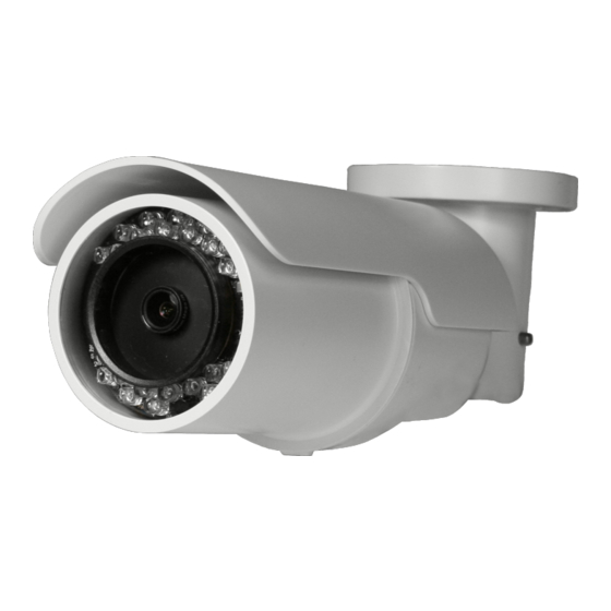
INTRODUCTION OVERVIEW The OpenEye CM-722I is a 2MP outdoor IP bullet camera built to provide superior video quality. The camera utilizes MJPEG or H.264 compression to provide video at resolutions up to 1080p (2MP), and is capable of dual and quad streaming at 720p (1MP). The CM- 722I is equipped with 23 IR LEDs and a mechanical IR cut filter for true day/night operation, allowing the camera to record high-resolution images at 0 Lux. -
Page 11: Getting Started
GETTING STARTED BOX CONTENTS Before proceeding, please check that the box contains the items listed here. If any item is missing or has defects, DO NOT install or operate the product and contact your dealer for assistance. Power Terminal CM-722I Camera (Cable included) Block M4 Inner Hex Self Tapping Screws... -
Page 12: Camera Overview
CAMERA OVERVIEW Before installing or connecting the camera, please refer to this section, including an overview of the all-in-one cable for reference. Dimensions 10.5” (266.7 mm) 2.75” (69.9 mm) • Length – 10.5 inches (84 mm) • Width – 2.75 inches (69.9 mm) •... -
Page 13: Connections
Connections Item Definition Remarks Network (with PoE) RJ-45 connector w/ LED Power (3-pin Terminal AC 24V-1 DC (-) Block) Reserved Power connection AC 24V-2 DC (+) Alarm I/O ALM_DI- ALM_DI+ Alarm connection ALM_DO- ALM_DO+ Audio I/O Pink Line In/Mic In Two-way audio transmission Green... -
Page 14: Micro Sd Card Slot And Reset Button
Micro SD Card Slot and Reset Button Use these photos to reach the Micro SD card slot, reboot button, and factory default button. Unscrew the camera housing to remove front cover. Micro SD card slot... - Page 15 Factory default button Reboot Button 31051AA...
-
Page 16: Installing The Desiccant
Installing the Desiccant To prevent condensation on the glass cover of the CM-722I, OpenEye recommends placing the desiccant in the camera before installation and replacing the desiccant each time the front cover is opened. Unfasten the screw on the camera housing and remove the front cover Carefully tear open the aluminum desiccant envelope and remove the desiccant. -
Page 17: Installation
Make sure that the camera’s power cable is correctly and firmly connected. Refer to the pin definition table on page 14. Note OpenEye recommends against using more than one power source at a time. Do not use a PoE power source when providing the camera with 12vDC or 24vAC power. -
Page 18: Ceiling Installation
CEILING INSTALLATION The IR Bullet IP Camera can be installed directly on a wall or ceiling provided it has enough strength to support the camera. Remove the IR Bullet IP Camera from packaging Connect power, Ethernet, Alarm and audio wires from ceiling or wall to the corresponding connectors of the cameras all-in-one cable. -
Page 19: Lens Adjustment
LENS ADJUSTMENT Unscrew the camera housing to remove front housing. Connect the power, audio, and alarm wires to their corresponding connectors. Refer to the pin definition table on page 14. Access the camera browser in order to view images. Refer to instructions on page X. Adjust the zoom/focus ring screw on the lens to set the desired zoom and focal length. -
Page 20: Camera Finder
OPENEYE IP FINDER Use the included IP Finder software to easily find your network cameras for initial setup. The OpenEye IP Finder software is included on the CD with all OpenEye IP devices. Finding IP Cameras Open the Software CD on the recorder. -
Page 21: Changing The Network Type
Log in to the camera with the appropriate User Name and Password. Note The default User name is Admin and the default Password is1234. The username and password are case sensitive. OpenEye recommends you change the Admin password for security reasons. Resetting the Camera If it is necessary to reset the camera to the factory default settings, hold down the Reset button (see Connections) for 30 seconds. -
Page 22: Connecting A Stream
OpenEye IP cameras using third party software like VLC media player (http://www.videolan.org). To connect the camera you may need to provide the stream URL. All OpenEye IP cameras are capable of delivering two RTSP streams, as well as streaming MJPEG over HTTP. -
Page 23: Connecting Over The Internet
There are some challenges with connecting to OpenEye IP cameras over WAN (internet) connections because the camera streams video over RTSP. RTSP is an excellent protocol for media and is now used on many IP cameras (including OpenEye) as the default streaming option. -
Page 24: Viewer Software
ActiveX controls and plug-in settings. For additional information on adjusting the settings of your Internet Explorer browser contact your system administrator or refer to openeye.net. If your internet browser asks for permission to install the ActiveX control, you must allow the ActiveX control to continue the installation. -
Page 25: Home
Home Screen Size Adjustment – Click the screen size buttons to adjust image display size x1/2 and full screen. Digital Zoom Control – In full screen mode, right-click to activate digital zoom and use the scroll wheel to zoom in/out. Talk –... -
Page 26: System
System Note The System tab is only accessible by the Administrator. System Host Name – The Host Name is used to identify the camera on your system. If camera- based Motion Detection is enabled and is set to send alarm message by Mail/FTP, the host name entered here will display in the alarm message. -
Page 27: Security
Security Admin Password To change the administrator password, type a new password in the Admin Password box and confirm below. Note The maximum length of the password is 14 characters. The following characters are valid: A-Z, a-z, 0-9, !#$%&’-.@^_~. 31051AA... -
Page 28: Add User
Add User The user name and passwords are limited to 16 characters. The maximum number of user accounts is 20. Type the new User name and Password. Select the appropriate check boxes to give the user Camera Control, Talk and Listen permissions. -
Page 29: Network
Every network device has a unique Media Access Control (MAC) address that can be used for identification. The MAC address is located on the bottom of each camera, and on the box label (the OpenEye IP Finder also displays the MAC address for identification). Record your camera’s MAC address for identification in the future. - Page 30 When using static IP address to log in to the IP Camera, you can access it either through OpenEye IP Finder software or type the IP address directly in the address bar of your internet browser. General • IP address – The IP Address is necessary for network identification.
-
Page 31: Ddns
DDNS DDNS (Dynamic Domain Name Service) is a service that allows a connection to an IP address using a hostname (URL) address instead of a numeric IP address. Most Internet Service Providers use Dynamic IP Addressing that frequently changes the public IP address of your internet connection. -
Page 32: Mail
Mail The camera can send an e-mail via Simple Mail Transfer Protocol (SMTP) when motion is detected or when the sensor input is activated. SMTP is a protocol for sending e-mail messages between servers. SMTP is a relatively simple, text-based protocol, where one or more recipients of a message are specified and the message text is transferred. -
Page 33: Ftp
The camera can send alarm message to a specific File Transfer Protocol (FTP) site when motion is detected or when the sensor input is activated. You can assign alarm message to up to two FTP sites. Enter the FTP details, which include server, server port, user name, password and remote folder, in the appropriate boxes. -
Page 34: Application
Application The CM-722I is equipped with one alarm input and one relay output to connect to an alarm system to catch event images. Refer to Camera Overview > Connections to connect alarm devices to the IP Camera if needed. Alarm Switch – Enable or disable the alarm function. Alarm Type –... - Page 35 • Upload Image by FTP – Select to assign an FTP site. When the alarm is triggered, event images will be uploaded to the configured FTP site at the rate of one jpeg image per second. • Record Stream to SD Card – Select the item and the alarm-triggered recording will be saved to your micro SD card.
-
Page 36: Motion Detection
Motion Detection Motion Detection allows the camera to detect motion and trigger alarms when motion in the detected area exceeds the determined sensitivity threshold value. In the Motion Detection page, there is a motion detection window (red box) displayed on the Live View Pane. - Page 37 When motion detection is activated, the Motion pop-up window will open. When motion is detected, the signals will be displayed on the Motion window as shown below. Motion Detection Turn motion detection on or off. The default setting is Off. Motion Detection Setting •...
- Page 38 Triggered Action You can specify which actions the camera should take when motion is detected. • Enable Alarm Output – This will activate the camera’s alarm output. • Record Stream to SD Card – Select this item and the motion detection recording will be stored in the Micro SD/SDHC card when motion is detected.
- Page 39 File Name – Enter a file name in the box, ex. image.jpg. The uploaded image’s file name format can be set in this section. Please select the one that meets your requirements. • Add date/time suffix File name: imageYYMMDD_HHNNSS_XX.jpg Y: Year, M: Month, D: Day H: Hour, N: Minute, S: Second X: Sequence Number •...
-
Page 40: Storage Management
Storage Management The CM-722I has an integrated microSD™ card that can be used to record video or images. The card slot is compatible with a microSD™ card up to 32GB. Device Information – Displays the storage total size and free space information of the included microSD™... -
Page 41: Recording
Recording The recording schedule allows you to set up scheduled recording to the microSD™ card. Recording Schedule – The camera can be set up to record continuously until the card is full (or overwrite old data, see the Storage Management section). The camera can also be set up to record only during a scheduled time. -
Page 42: Snapshot
Snapshot The camera supports a JPEG snapshot function. You can specify a storage location for the snapshot images. The default location is: C:\. Note If you are using Windows Vista or 7, you will need to change the Snapshot location. Windows UAC does not allow internet programs to write directly to C:\ for security reasons. -
Page 43: Information
Information The Information page contains the camera’s System Log, User Information and Parameter List. System Log Click System Log to view the system log file. The content of the file provides useful information about configuration and connections. 31051AA... -
Page 44: View User Information
View User Information The Administrator can view each user’s login information and privileges on the View User Information page. All users for the camera are listed under User information. The example below shows that the Admin password is 1234 and there is one user named User with the password 4321. -
Page 45: Parameter List
Parameter List Click Parameter List to view the system parameter settings. 31051AA... -
Page 46: Software Upgrade
Software Upgrade Upgrading the Camera Viewer Software Note Make sure the new firmware file is available before starting a software upgrade. Click Browse and select the firmware file. Note Do not change the file name, or the system will not be able to update to the new firmware. - Page 47 When the upgrade process is complete the viewer will return to the Home page. After updating it is important to make sure the camera viewer software is updated: Close your browser. Go to the Windows Control Panel and double-click Add or Remove Programs. Locate the Camera Viewer software on the Currently installed programs list, and click Remove to uninstall the previous software version.
-
Page 48: Maintenance
Maintenance On the Maintenance page you can export the cameras current configuration, or import the configuration for a camera. Use the factory default page to reset the IP Camera to factory default settings if necessary. Note Do not import configuration files from different models of cameras. Set Default –To reset the IP camera to the factory default settings, including the default IP address, click Set Default. -
Page 49: Video And Audio Streaming Settings
Video and Audio Streaming Settings On the Streaming tab, you can configure specific video resolution, video compression mode, video protocol and audio transmission mode. Video Format Select the desired video resolution for the camera on the Video Format page. The DVR will record video based on the resolution selected here. -
Page 50: Video Rotate Type
Video Rotate Type You can change the orientation of the video output if necessary. • Normal transmits the image as the camera sees it. • Flip transmits the image upside down and mirrored. • Mirror transmits a mirror image. • 180 degree transmits the image upside down. -
Page 51: Video Compression
Video Compression You can select an MJPEG/H.264 compression mode on the video compression page appropriate for your application. You can also select to display compression information on the Home page. MJPEG compression settings include: • high compression, low bit rate, low quality •... -
Page 52: Video Ocx Protocol
Video OCX Protocol On the Video OCX protocol page, you can select different protocols for streaming media over the network. In the case of multicast networking, you can select the Multicast mode. Video OCX protocol setting options include: • RTP over UDP •... -
Page 53: Frame Rate Control
Frame Rate Control Setting the camera to transmit fewer frames can save bandwidth. Each of the MJPEG and H.264 streams can have a separate frame rate setting from 1 to 30 frames per second Note When set to 1920 x 1080, the max frame rate decreases to 15 frames per second. -
Page 54: Video Mask
Video Mask You can use the video mask page to define a privacy mask to keep users from viewing parts of the image. You can add two privacy masks and choose a color to obscure the live view from users. Active Mask Function •... -
Page 55: Audio
Audio On the Audio page, the Administrator can select an audio transmission mode and audio bit rate. Note Audio monitoring and recording laws vary from location to location. It is highly recommended that you consult your local, state and federal laws to verify that you are in compliance before implementing audio recording. -
Page 56: Server Gain Setting
Server Gain Setting Set the audio input/output gain levels for sound amplification. The audio gain values range from 1 to 6. Sound can be turned off if audio gain is set to Mute. Bit Rate Selectable audio transmission bit rate include: 16 kbps (G.726) 24 kbps (G.726) 32 kbps (G.726) -
Page 57: Camera
Camera Exposure The exposure is the amount of light received by the image sensor and is determined by the width of lens diaphragm opening (iris adjustment), the amount of exposure by the sensor (shutter speed) and other exposure parameters. Full Auto Mode •... -
Page 58: White Balance
White Balance A camera needs to find reference color temperature, which is a way of measuring the quality of a light source, for calculating all the other colors. The unit for measuring this ratio is in Kelvin (K). Users can select one of the White Balance Control modes according to the operating environment. -
Page 59: Contrast
Contrast Correct the contrast of the entire image by adjusting the Contrast level, ranging from -6 ~ +19. Saturation Adjust the saturation of color components in an image through the Saturation function, which is adjustable from -6 ~ +19. Digital Zoom Zoom in to the center of the image. -
Page 60: Specifications
SPECIFICATIONS CAMERA SPECIFICATIONS Model CM-722I Image Sensor 1/2.7” Progressive CMOS Imaging DSP Ambarella A5S IP Rating IP66 Type / Format H.264 / MJPEG Wide Dynamic Range Digital WDR Minimum Illumination 0.2 LUX (Color) / 0.02 LUX (B&W) / 0 LUX (IR LED) Day / Night Yes (True Day / Night) + IR LED 15IPS @1920 x 1080 (2MP),... -
Page 61: Ir Specifications
IR SPECIFICATIONS Model CM-722I IR LEDs 23 IR LEDs (850nm) IR Range Up to 50 ft (15 m) IP SPECIFICATIONS Model CM-722I Video Compression H.264 / MJPEG H.264 ONLY, MJPEG ONLY, H.264 + H.264, H.264 + MJEG, H.264 + H.264 + H.264, H.264 + H.264 + MJPEG, H.264 + H.264 + H.264 + H.264, Dual Streaming... -
Page 62: Appendix A
APPENDIX A SET UP INTERNET SECURITY If the installation of ActiveX Control is blocked, you will need to either set the Internet Security Level to the default setting, or change the ActiveX controls and plug-ins setting. Setting Internet Security Level to Default Open Internet Explorer. -
Page 63: Adjusting Activex Controls And Plug-Ins
Adjusting ActiveX Controls and Plug-ins Open Internet Explorer. Click the Tools tab in the menu bar. Click Internet Options. Click Custom Level. The Security Settings window will pop up. Under ActiveX Controls and Plug Ins, set all items to Enable or Prompt. Items may vary according to your version of Internet Explorer. - Page 65 © 2012 OpenEye All rights reserved. No part of this publication may be reproduced by any means without written permission from OpenEye. The information in this publication is believed to be accurate in all respects. However, OpenEye cannot assume responsibility for any consequences resulting from the use thereof.
Need help?
Do you have a question about the CM-722 and is the answer not in the manual?
Questions and answers