Table of Contents
Advertisement
Advertisement
Table of Contents

Related Manuals for Denon MC3000


Summary of Contents for Denon MC3000
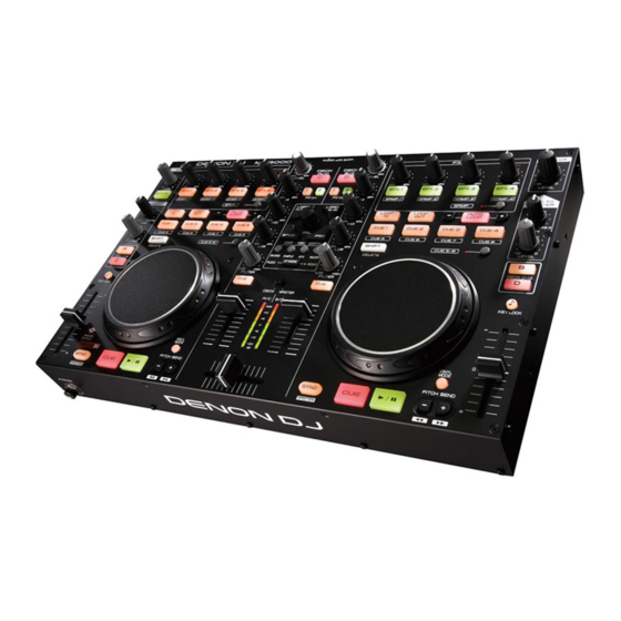
- Page 1 Professional DJ Controller MC3000 Owner’s Manual...
-
Page 2: Fcc Information
This product, when installed as indicated in the instructions contained in this manual, meets FCC the presence of important operating and maintenance (servicing) instructions in the requirements. Modification not expressly approved by DENON may void your authority, granted by literature accompanying the appliance. -
Page 3: Important Safety Instructions
IMPORTANT SAFETY INSTRUCTIONS CAUTION: (English) To completely disconnect this product from the mains, disconnect the plug from the wall socket READ BEFORE OPERATING EQUIPMENT outlet. The mains plug is used to completely interrupt the power supply to the unit and must be within This product was designed and manufactured to meet strict quality and safety standards. - Page 4 n NOTE ON USE/HINWEISE ZUM GEBRAUCH/OBSERVATIONS RELATIVES A L’UTILISATION/ NOTE SULL’USO/NOTAS SOBRE EL USO/ALVORENS TE GEBRUIKEN/OBSERVERA WARNINGS WARNHINWEISE AVERTISSEMENTS AVVERTENZE ADVERTENCIAS WAARSCHUWINGEN VARNINGAR • Handle the power cord carefully. • Gehen Sie vorsichtig mit dem • Manipuler le cordon • Manneggiate il cavo di • Maneje el cordón de energía • Hanteer het netsnoer • Hantera nätkabeln varsamt.
- Page 5 • D ECLARATION OF CONFORMITY • D ECLARACIÓN DE CONFORMIDAD (English) (Español) We declare under our sole responsibility that this product, to which this declaration relates, is Declaramos bajo nuestra exclusiva responsabilidad que este producto al que hace referencia in conformity with the following standards: esta declaración, está...
- Page 6 A NOTE ABOUT RECYCLING: This product’s packaging materials are recyclable and can be reused. Please dispose of any materials in accordance with the local recycling regulations. When discarding the unit, comply with local rules or regulations. Batteries should never be thrown away or incinerated but disposed of in accordance with the local regulations concerning battery disposal.
-
Page 7: Table Of Contents
USB cable ................1 Adjusting the microphone input level ········································10 Connections CD-ROM ·············································································3 Headphone monitor ···································································10 • MC3000 Resource CD-ROM ..........1 LINE TO MASTER function ························································11 Preparations ··················································································3 • DJ software (U.S.A and Canada models) Adjusting the level balance of lines 1/2 ······································11 Cables used for connection ··························································3 Virtual DJ LE ................. -
Page 8: About This Manual
About this manual Main features Cautions on handling 1. Reliable design • Before turning the power switch on n Symbols • High grade steel cabinet and self-illuminating rubber buttons. Check once again that all connections are correct and that there are This symbol indicates a reference page on • Equipped with a LINE TO MASTER function that enables backup no problems with the connection cables. -
Page 9: Connections
Connections NOTE Input terminal connection Output terminal connections • Do not plug in the power cord until all connections have been completed. Connecting a microphone/external devices Outputting to an amplifier/powered • When making connections, also refer to the operating instructions of the other components. speakers and recording devices Coaxial • Insert the plugs securely. -
Page 10: Connecting To A Computer
Connecting to a computer Connecting the power cord Use the supplied USB cable to connect the unit with a computer so Insert the supplied AC adapter DC plug into the DC IN jack of the unit n Automatic driver installation that USB MIDI and USB AUDIO signals can be sent and received. -
Page 11: Installing And Setting Up Supplied Software
Use the following steps to install the supplied ASIO drivers. • When using a Mac, no installation is required. Insert the supplied “MC3000 Resource CD-ROM” The license agreement screen appears. If you agree, A screen for verifying the folder in which the ASIO into the computer. - Page 12 Installing the ASIO driver (Windows only) A screen for verifying whether or not to create a When the following installation completion screen is The installation start screen is displayed. desktop shortcut appears. displayed, click “Close”. Click “Next >”. To create a shortcut, check the check box and click Installation begins.
-
Page 13: Starting
OK/Cancel This window is used for automatically displaying When the DENON DJ ASIO driver “ASIO Control Panel” is opened from the DJ software or desktop icon, all connected DENON DJ devices in a list. Use this button to close the ASIO control panel, the DENON DJ ASIO driver appears in the ASIO Control Panel. -
Page 14: Installing Traktor
Installing TRAKTOR LE 2 Use the following steps to install the DJ software “TRAKTOR LE 2” in the supplied DVD-ROM. Installation onto a Mac computer Installation onto a Windows computer Insert DVD-ROM “TRAKTOR LE 2” into your Insert DVD-ROM “TRAKTOR LE 2” into your computer. computer. The TRAKTOR LE 2 disc icon is displayed on the desktop. The browse screen for the disc drive is displayed. -
Page 15: Installing Virtual Dj
Installing Virtual DJ LE Use the following steps to install the DJ software “Virtual DJ LE” in the supplied CD-ROM. Installation into Mac computers Installation into Windows computer Insert CD-ROM “Virtual DJ LE” into your Insert CD-ROM “Virtual DJ LE” into your computer. computer. The Virtual DJ icon is displayed on the desktop. The browse screen for the disc drive is displayed. • When the browse screen is not displayed, click the disc drive on Double-click the Virtual DJ LE icon. -
Page 16: Basic Operation
Basic operation This section describes operations of the unit without using the DJ software. Top panel • For information about how to operate the DJ software, see the instruction manual for the DJ software or the help menu. • For information about the buttons on the unit for operating the DJ software and their functions, see the following pages. MIC LEVEL DUCKING MASTER LEVEL • TRAKTOR LE 2/PRO 2······Page 19 –... -
Page 17: Line To Master Function
Top panel Adjusting the sensitivity of the LINE TO MASTER function LINE TO touch sensor Even if this device is not connected to a computer, the audio from SHIFT SEL. LOAD A/C LOAD B/D SHIFT MASTER PAN external devices such as CD players connected to the line 1/2 input The unit can control the sensitivity of the touch sensor for the Jog terminals can be output as the master level. -
Page 18: Jog Wheel Lock Function
• USB 1/2 channel input DJ software master Locking the jog wheel • USB 3/4 channel input DJ software cue monitor • USB 1/2 channel output MC3000 line 1 audio signal Hold down SHIFT for DECK A or B, and press VINYL • USB 3/4 channel output... -
Page 19: Midi Command Input/Output
MIDI command input/output This unit is equipped with a USB MIDI command input/output function. This function enables the unit to control the DJ software in the computer, and lights the main unit display (LEDs). • If TRAKTOR LE 2/PRO 2 and Virtual DJ LE/PRO are used normally, there is no need to switch MIDI command settings or the MIDI channel. Doing so may cause undesired operation or no operation at all. Set when TRAKTOR LE 2/PRO 2 and Virtual DJ LE/PRO are customized for expanded operation, or when other DJ software is used. -
Page 20: Switching Midi Input/Output Channels
Top panel MIDI command input/output BROWSE Setting the MIDI command transmission Switching MIDI input/output channels SAMPLE RECORD interval time BROWSE/SAMPLE/EFX/RECORD Press one of while CUE 1 – 4 CUE 1 – 4 SEL. holding down SHIFT Depending on the computer specifications and OS type, the computer may not be able to receive the MIDI commands transmitted from this unit correctly. -
Page 21: Midi Command List
MIDI command input/output MIDI command list n Send command MIDI command MIDI command Items Items Command Number Value Command Number Value CUE8 D# 5 CUE (DECK A) C# -1 JOG WHEEL TOUCH CUE (DECK C) D -1 EFX.2 SW (FX2) A# 5 DECK CHG. - Page 22 MIDI command input/output n Reception commands MIDI command Items Command Number Value MIDI command Items EFX.1 KNOB (LEFT) (Lit display (LED)) Command Number Value in SAMP mode VINYL MODE EFX.2 KNOB (LEFT) KEY LOCK in SAMP mode EFX.3 KNOB (LEFT) SYNC in SAMP mode CUE1 EFX.4 KNOB (LEFT) CUE1 Dimmer...
- Page 23 MIDI command input/output MIDI command MIDI command Items Items (Lit display (LED)) (Lit display (LED)) Command Number Value Command Number Value PLAY CUE (DECK D) LOOP IN CUE Dimmer (DECK D) LOOP IN Dimmer DUCKING LOOP OUT CF MODE (AUDIO) LOOP OUT Dimmer CF MODE (VIDEO) AUTO LOOP...
-
Page 24: Part Names And Functions
Part names and functions Top panel q Audio input/output part This section describes the top panel in the following sections: q Audio input/output part, w TRAKTOR LE 2/PRO 2 and e Virtual DJ LE/PRO. Read descriptions for your DJ software. For buttons not explained here, see the page indicated in parentheses ( ). Microphone input level adjustment knob Master output volume adjustment knob (MIC LEVEL) ·············································································... -
Page 25: Traktor Le 2/Pro 2
Top panel w TRAKTOR LE 2/PRO 2 Effects/sample adjustment knob Effects ON/OFF switch button (EFX.1/EFX.2/EFX.3/EFX.4) (EFX.1/EFX.2/EFX.3/EFX.4) SAMP SAMP the following operations differ the following operations differ depending on whether this is ON or OFF. depending on whether this is ON or OFF. OFF: Uses the effects. - Page 26 Top panel ON: Uses the sampler. Auto loop and loop size adjustment buttons (This function is enabled when the upgraded (AUTO LOOP –/+) version TRAKTOR PRO 2 (sold separately) is AUTO LOOP • switches auto loop ON/OFF. used.) –/+ • Use to adjust the loop size. EFX.1/EFX.2/EFX.3/EFX.4: SHIFT • Hold down and press this button to Plays back the sample.
- Page 27 Top panel Shift button (SHIFT) Play/pause button ( SAMP. Hold down and press this button to Hot cue switch button and display batch playback the sample slot. (CUE 5 – 8) Also, The operations differ as follows The button switches CUE 1 – 4/CUE 5 – 8. depending on whether deck A (B) or C (D) are • When CUE 5 –...
- Page 28 Top panel Mixer control channel selection button Track selection knob (SEL.) (DECK A/C , DECK B/D) Turn the knob to scroll through the browser list, Sets the mixer control channel to A(C) or B(D). and press the knob to select a file. DECK CHG.
- Page 29 Top panel RECORD window switch button Level meter display switching switch (RECORD) (DECK, MASTER) SHIFT Hold down and press this button for Channels displayed by the level master can be more than 1 second to assign each DECK to the selected from the following display modes.
-
Page 30: Virtual Dj Le/Pro
Top panel e Virtual DJ LE/PRO Effects/sample adjustment knob FX ON/OFF switch button (EFX.1/EFX.2/EFX.3/EFX.4) (EFX.1/EFX.2/EFX.3/EFX.4) The following operations differ depending on The following operations differ depending on SAMP. SAMP. whether is ON or OFF. whether is ON or OFF. OFF: Uses the effects. ON: Uses the sampler. - Page 31 Top panel Loop point setting button Deck switch button (DECK CHG.) (LOOP IN/LOOP OUT) Selects the deck. Sets the loop in point and loop out point. Key lock button (KEY LOCK) SHIFT • Hold down and operate to erase the With this ON, the key does not change even if loop settings.
- Page 32 Top panel VINYL switching button (VINYL MODE) FX ON/OFF switching button (FX ON 1/2) ON: Switches to VINYL mode. FX1: Switches the Flanger function ON/OFF. SHIFT • The touch sensor is enabled when in VINYL • Hold down and press this button to mode. switch the Brake function ON/OFF. OFF: Switches to BEND mode. FX2: Switches the Beat Grid function ON/OFF. SHIFT • The touch sensor is disabled when in BEND • Hold down...
- Page 33 Top panel Track selection knob (SEL.) Window switch button (BACK/FWD) Turn the knob or press to select a file. Functions The function differs according to the window. differ depending on the window. BROWSER: Moves between folders, tracks, Turn the track selection knob: playback lists and side lists.
- Page 34 Top panel SAMPLE window switch button Filter cut off adjustment knob (FILTER) (SAMPLE) Adjusts the filter cut off frequency for each SHIFT Hold down and press this button for channel. more than 1 second to assign each DECK to the Channel cue button (CUE DECK A/B/C/D) following MIDI channels.
-
Page 35: Front Panel
Front panel Rear panel For buttons not explained here, see the page indicated in parentheses ( ). For buttons not explained here, see the page indicated in parentheses ( ). Headphone jack (PHONES) ························ (10) USB terminal (USB) ····································· (4) Theft protection lock hole Connect to an anti-theft wire. -
Page 36: Troubleshooting
Troubleshooting If a problem should arise, first check the following: 1. Are the connections correct? 2. Is the set being operated as described in this owner’s manual? 3. Is the external device (player or effects processor) operating correctly? If this unit does not operate properly, check the items listed in the table below. If the symptom is not covered on the check list, contact your dealer or service centers. -
Page 37: Specifications
Specifications n Audio (0 dBu=0.775 Vrms, 0 dBV =1 Vrms) n General • LINE inputs 2 Stereo USB MIDI input/output: IN: 1ch, OUT: 1ch MIDI 1.0, USB B Unbalanced RCA terminal MASTER meter: PPM 7 Point LED –20 – +10 dB, Peak Input impedance: 51 kΩ CH fader: 1 1/4 in. (45 mm) slim type fader Level: 0 dBV... -
Page 38: Index
ENGLISH Index AC adapter ··························································· 4 Microphone ························································ 10 ASIO driver ··························································· 5 MIDI command ······································ 13, 14, 15 MIDI input/output channels ································ 14 Cable ···································································· 3 Balanced phone plug cable ································ 3 Power on/off ······················································ 10 Coaxial cable for microphone ····························· 3 RCA pin plug cable·············································... -
Page 39: Signal System Chart
Signal system chart Master Level for METER... - Page 40 Dimensions Unit: in. (mm) 5/16 (8.0) 5/16 (8.0) 15 3/4 (400.0) 27/32 (21.6) 1 31/32 (50.0) Weight: 6 lbs 9.8 oz (3.0 kg) (AC Adaptor 10.6 oz (0.3 kg))
- Page 41 3520 10061 00AP...
Need help?
Do you have a question about the MC3000 and is the answer not in the manual?
Questions and answers