Table of Contents
Advertisement
Ver. 1
SERVICE MANUAL
MODEL
JP
E3
E2
EK
K2A E1C E1K EUT
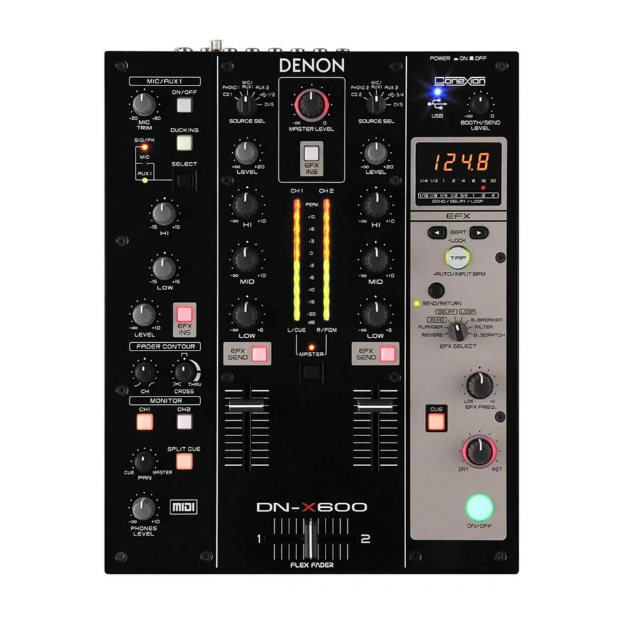
DN-X600
DJ MIXER
• For purposes of improvement, specifi cations and design are subject to change without notice.
• Please use this service manual with referring to the operating instructions without fail.
• Some illustrations using in this service manual are slightly different from the actual set.
D&M Holdings Inc.
S0080-1V01DM/DG1008
Copyright 2010 D&M Holdings Inc. All rights reserved.
WARNING: Violators will be prosecuted to the maximum extent possible.
Advertisement
Table of Contents

Subscribe to Our Youtube Channel
Related Manuals for Denon DN-X600


Summary of Contents for Denon DN-X600
- Page 1 Ver. 1 SERVICE MANUAL MODEL K2A E1C E1K EUT DN-X600 DJ MIXER • For purposes of improvement, specifi cations and design are subject to change without notice. • Please use this service manual with referring to the operating instructions without fail.
-
Page 2: Safety Precautions
SAFETY PRECAUTIONS The following check should be performed for the continued protection of the customer and service technician. LEAKAGE CURRENT CHECK Before returning the unit to the customer, make sure you make either (1) a leakage current check or (2) a line to chassis resistance check. -
Page 3: Note For Schematic Diagram
NOTE FOR SCHEMATIC DIAGRAM WARNING: Parts marked with this symbol z have critical characteristics. Use ONLY replacement parts recommended by the manufacture CAUTION: Before returning the unit to the customer, make sure you make either (1) a leakage current check or (2) a line to chassis resistance check. If the leakage current exceeds 0.5 milliamps, or if the resistance from chassis to either side of the power cord is less than 460 kohms, the unit is defective. -
Page 4: Technical Specifications
TECHNICAL SPECIFICATIONS n Audio (0 dBu=0.775 Vrms, • Headphone output Stereo 0 dBV =1 Vrms) Load impedance: 40 Ω • PHONO inputs 2 Stereo Level: 100 mW Unbalanced RCA terminal • USB audio output 4 Stereo(8 Monaural) 24bit, Input impedance: 47 kΩ... -
Page 5: Caution In Servicing
CAUTION IN SERVICING Initializing DN-X600 DN-X600 initialization should be performed when the μcom, peripheral parts of μcom, and Digital P.W.B. are replaced. 1. Turn off the power using POWER ON/OFF button. 2. Press POWER ON/OFF button while simultaneously pressing EFX SEND1 and EFX SEND1 buttons. - Page 6 DISASSEMBLY • Disassemble in order of the arrow of the fi gure of following fl ow. • In the case of the re-assembling, assemble it in order of the reverse of the following fl ow. • In the case of the re-assembling, observe "attention of assembling" it. •...
- Page 7 About the photos used for descriptions in the "DISASSEMBLY" section. • The direction from which the photographs used herein were photographed is indicated at "Direction of photograph: ***" at the left of the respective photographs. • Refer to the table below for a description of the direction in which the photos were taken. •...
- Page 8 (2) Remove the screws. Direction of photograph: B Direction of Direction of photograph: C photograph: D Direction of photograph: A (3) Disconnect the connector wire and FFC Cable, then loose the wire clamper. TOP CHASIS SUB ASSY FFC cable Direction of photograph: A WIRE CLAMPER N041 BOTTOM CHASSIS SUB ASSY...
- Page 9 2. TOP PANEL PWB SUB ASSY Proceeding : TOP PANEL SUB ASSY TOP PANEL PWB SUB ASSY → (1) Remove the knobs. KNOB (2) Remove the screws. (3) Remove the Nuts, LENS LED and LENS RING, then disconnect the connector wire. LENS LED LENS RING VOL N041...
- Page 10 (4) Remove the secrews, then remove the STAY GND. STAY GND 3. 7SEG PWB Proceeding : TOP PANEL SUB ASSY TOP PANEL PWB SUB ASSY 7SEG PWB → → (1) Disconnect the connector wire, then remove the PCB SUPPORT. N132 PCB SUPPORT TOP PANEL PWB 7SEG PWB...
- Page 11 4. HEAD PHONE PWB Proceeding : TOP PANEL SUB ASSY HEAD PHONE PWB → (1) Remove the screw, Nuts and Washers. NUT/WASHE Direction of photograph: A (2) Disconnect the connector wires. N068 N044 5. SLIDE SW PWB Proceeding : TOP PANEL SUB ASSY SLIDE SW PWB →...
- Page 12 6. MAIN PWB Proceeding : TOP PANEL SUB ASSY MAIN PWB → (1) Disconnect the connector wire and FFC Cable, and remove the tape. FFC Cable Clamper CY081 FFC Cable tape (2) Remove the screws. Direction of photograph: B 7. MIC PWB Proceeding : TOP PANEL SUB ASSY MIC PWB...
- Page 13 8. IO PWB Proceeding : TOP PANEL SUB ASSY HEAD PHONE PWB SLIDE SW PWB → → MAIN PWB MIC PWB → → (1) Remove the screws. Direction of photograph: B (2) Disconnect the connector wires. SUPPORT N021 STAY PWB MAIN...
-
Page 14: Special Mode
SPECIAL MODE 1. Special mode setting button b Press the POWER ON button to turn on while pressing buttons A and B. Mode Button A Button B Contents Version display, LED Check, SW CHECK, VR Check, Total running Service Mode time (Clear total runnig time), ROM/RAM Access test, USB MIDI OUT test, EUP mode test Version Up Mode... - Page 15 2.1. Version display EFX SERECTOR is REVERB and press TAP button. Display order «_SYS»→«xxxx(system Ver.)»→«_dSP»→«xxxx(DSP Ver.)» ever 1 sec. Press [EFX SEND / RETURN] button:Back to the Service Top. 2.2. LED Check EFX SERECTOR is FLANGER and press TAP button. Press TAP button to order, and the following mode.
- Page 16 2.4. VR Check • EFX SERECTOR is DELAY and press TAP button. (1) Checking the operation of each panel VR. (Total 19, CH Fader 2, X Fader 1, Selector 3, Slide switch 5) (2) Turned the volume amount will display in resolution number 1024. (3) Displays the number corresponding to the selected location of the source selector.
- Page 17 2.6. ROM/RAM Access test • EFX SERECTOR is B.BREAKER and press TAP button. (1) Press BEAT button, select «_run». Presse TAP button. (2) FlashROM (2MB) and SD-RAM (8MB) then Reads to accessible. Address (space cache disabled), and two bytes for each increment.
-
Page 18: About Replace The Microprocessor With A New One
Refer to "Update procedure" or "writing procedure", when you should be write-in the software. VERSION UPGRADE PROCEDURE OF FIRMWARE 1. preparation (1) Connect the computer by USB cable. DN-X600 : Type B (2) UPDATEER Dowload Dennon SDI site. for Windows : DDJUpdater-2.0.msi for Mac : DDJ Updater.app... - Page 19 (2) Click the Next. (3) Check the I accept the terms of the license agreement,and Click the Next. (4) Click the Next.
- Page 20 (5) Click the Next. (6) Click the Next. (7) The Setup Status bar appears.
- Page 21 (8) Click the Close. 3. Update Firmware [Caution] During the loading and upgrading the power OFF and set, PC or please do not remove the cable connection. Also, please press the button of a keyboard and computer sets. (1) Connect the USB cable from PC to the unit. (2) Press the POWER ON button to turn on while pressing buttons DUCKING and SELECT.
- Page 22 (5) Click the File menu. And click the Open. Select the latest fi rmware. (6) Click the Load.
- Page 23 (7) The Setup Status bar appears. (8) Click the OK.
- Page 24 (9) Click the Execute. (10) The Setup Status bar appears.
- Page 25 (11) Click the OK. (11) Confi rm “donE” is displayed in the panel. Failure to upgrade to the unit "FAIL" is displayed. Failure to upgrade to the PC "Version up was not completed." is displayed. Then "Execute" click again.
- Page 26 4. Error message & trabuleshooting Message Solution File is invalid. Please select the update fi le for this unit. Load failed. Check the connection, and retry Please try again step 1). Loaded data is invalid. Check the fi le Please select the update fi le for this unit. Version up was not completed Please try again step 1).
-
Page 27: Troubleshooting
TROUBLE SHOOTING FLOW CHART NO.1 (8U-110086-1 : IN/OUT/PWR UNIT) The power cannot be turned on. O.K. N.G. Is the fuse normal? See FLOW CHART NO.2 <The fuse blows out.> O.K. Check if there is any leak or short-circuiting on the primary circuit component, and replace it if N.G. - Page 28 FLOW CHART NO.3 (8U-110086-1 : IN/OUT/PWR UNIT) +1.2V is not outputted. O.K. N.G. See FLOW CHART NO.1 Is the +3.3V line voltage normal? <Is the +3.3V line voltage normal?> O.K. Check U5102 and the periphery circuit, and replace it if defective FLOW CHART NO.4 (8U-110086-1:IN/OUT/PWR UNIT) +3.3V is not outputted.
- Page 29 FLOW CHART NO.6 (8U-110086-1 : IN/OUT/PWR UNIT) -15V is not outputted. O.K. N.G. Is the fuse normal? See FLOW CHART NO.2 <The fuse blows out.> O.K. N.G. Is the voltage of +15V or more supplied to collector Check D5115,L5103,C5117,C5125,C5518 and terminal of Q5110 replace it if defective.
- Page 30 FLOW CHART NO.8 (8U-110087-1 : PANEL UNIT) The key operation is not functioning. O.K. Are the contact point and the installation state of N.G. the key switches (S401~S411,S413,S414,S416, Re-install the switches correctly or replace the poor S418~S420), rotary switches (S433,S434,S437) switch.
- Page 31 FLOW CHART NO.9 (8U-310012 : MAIN UNIT,8U-110086-1 : IN/OUT/PWR UNIT,8U-110086-2 : HP JACK UNIT, 8U-110087-7 : SLIDE SW UNIT) The Slide switches operation is not functioning. O.K. Are the contact point and the installation state of the N.G. Re-install the switches correctly or replace the poor Slide switches (S701,S702,S3402,S3800,S3801) switch.
- Page 32 FLOW CHART NO.10 (8U-110086-1 : IN/OUT/PWR UNIT) Function of sound for master output do not operate normally. O.K. ・Set the SOURCE SEL switch to "CD". ・Set the CROSS of FADER CONTOUR to "THRU". ・Set the LEVEL volume to "12:00". Check the input signal from N232 to U2100 and ・Set the channel fader to "MAX".
- Page 33 FLOW CHART NO.11 (8U-110086-1 : IN/OUT/PWR UNIT) Function of sound for master output do not operate normally. O.K. Is 2pin of N231 (Operational amplifi er built-in switch N.G. ・Set the SOURCE SEL switch to "CD". control signal)L, and has been the Q3100 collector ・Set the CROSS of FADER CONTOUR to "THRU".
- Page 34 Personal notes:...
-
Page 35: Block Diagram
BLOCK DIAGRAM GND0 BOOTH MASTER 8U-310012B USB B FADER 8U-110086-1 CD1 PHONO1 CD2 PHONO2 MASTER AUX2-BOOTH AUX1 RTN/AUX2 /SND (Unbal) ST/MONO /RTN-SND MAIN UINT IN/OUT/PWR UNIT (BAL) (PHONO) FG20 8U-110087-7 FG31 48MHz SLIDE SW UNIT CPU(USB) MUTE MUTE 3pin KR N031 +15V +15V... -
Page 36: Level Diagram
LEVEL DIAGRAM... -
Page 37: Wiring Diagram
WIRING DIAGRAM N131 CX131 CX252 N252 N131 N132 8U-110087-6 MIC UNIT 8U-110087-2 8U-110087-7 7SEG UNIT SLIDE SW UNIT N232 CX232 J101 J101 8U-110087-3 N068 N069 J102 J102 FADER UNIT (CH1) J106 J106 J103 J103 8U-110087-4 J104 J104 FADER UNIT (CH2) J105 J105 N044... -
Page 38: Printed Wiring Boards
PRINTED WIRING BOARDS IN/OUT/PWR UNIT (COMPONENT SIDE) 631010086108P 8U-110086-1 C5517 C5520 IN/OUT/PWR UNIT B3750 JV292 C3151 N065 JV196 B2200 C3131 C3112 C2420 C2418 22.5 C2413 JV198 C3119 22.5 J3501 JV112 12.5 C3146 JV209 JV197 22.5 JV281 JV290 C3108 C3142 JV282 JV170 JV42 JV289... - Page 39 IN/OUT/PWR UNIT (FOIL SIDE) R3408 U3400 C2177 R2174 C3134 R3141 Q5107 Q5104 R3143 R3137 R3139 C3138 R3149 C3417 C3137 R3144 C3408 C3140 U2107 R5507 U3103 C3148 U3102 R3106 C3144 C3416 C2178 R5515 C3423 D3401 R2176 R3112 D5119 C3406 R3151 R3109 R3107 R3125 R2428...
- Page 40 PANEL UNIT (COMPONENT SIDE) 631010087101P D146 (CC) D151 V418 8U-110087-1 JV323 12.5 PANEL UNIT 15.0 D143 JV320 D154 S418 JV319 JV317 D149 17.5 JV314 17.5 JV310 JV309 JV313 V406 15.0 JV308 JV307 D148 12.5 N131 17.5 JV306 D152 D142 JV303 17.5 JV301 JV299...
- Page 41 PANEL UNIT (FOIL SIDE) C442 Q114 C437 C436 R139 C443 R133 U102 Q107 D112 C128 R193 C411 C101 U404 R401 C105 U103 D411 D412 D407 D404 C416 C414 C406 R913 R926 R109 C407 R925 R106 U403 R112 R115 C402 C468 R104 C480 R101...
- Page 42 MIC UNIT (COMPONENT SIDE) HP JACK UNIT (COMPONENT SIDE) SLIDE SW UNIT (COMPONENT SIDE) 7SEG UNIT (COMPONENT SIDE) JV37 JV171 JV162 JV160 C610 JV158 JV323 17.5 V601 JV149 20.0 N132 JV324 12.5 JV139 JV127 25.0 S3800 JV118 JV99 JV96 N066 JV88 J601 JV81...
- Page 43 MAIN UNIT (COMPONENT SIDE) CY081 CX131 CX131 CY081 R311 CC709 CC706 R314 CC706 CC709 FB301 CC702 R315 FB301 CC702 R313 CC705 CC708 R310 CC708 CC705 R309 X103 R769 R308 X101 R403 R312 CX252 C757 R425 FB307 R307 C203 C758 R422 FB306 R305 C202...
- Page 44 MAIN UNIT (FOIL SIDE) R778 R778 R779 R779 C313 C315 C308 R408 R410 R409 C316 IC704 R411 R415 R764 R720 R332 R721 R722 R416 R417 R420 R278 R764 R723 R418 R423 R277 R724 IC106 R276 R429 C743 R352 R159 R183 R726 C744 R336...
-
Page 45: Schematic Diagrams
CX141 OPEN +3V3 +1V2 FB109 V3SH V1SH V3SHA 18PG121 FB110 18PG121 C157 47/16 R104 GRM32 SHDQ16 IC107 R167 SHDB16 R207 SHDQ17 R168 SHDB17 PLAY4/EUPONOFF 3.3K W9864G2IH-6 SHDQ18 R169 SHDB18 SHDQ19 R170 SHDB19 SHDQ0 DQ15 SHDQ15 SHDQ20 R171 SHDB20 VSSQ SHDQ21 R196 VCCQ R172... - Page 46 +3V3 CX142 OPEN V3AS +3V3 FB504 18PG121 1pin 9pin 14pin 27pin 43pin 49pin 1pin 9pin 14pin 27pin 43pin 49pin DSP_CLK DGND IC501 [TOP VIEW] DSP16.9M DSP16.9M R501 OPEN D710E001ZDH300 DSP_CLK V3AS V3AS DSP_CLK DGND R585 OPEN SHDB0 SHDB0 AXRO[6] R530 OPEN SHDB1 SHDB0...
- Page 47 + 3V3 USB1DAT USB1DAT R415 USB1DAT USBD_1 C16 DGND USB2DAT R416 USB2DAT USB2DAT USBD_2 C15 USB3DAT USB3DAT R417 USB3DAT USBD_3 D15 USB4DAT USB4DAT R418 USB4DAT USBD_4 D16 ADDAT1 ADDAT1 ADDAT1 ADDAT1 F11 ADDAT2 ADDAT2 ADDAT2 ADDAT2 F12 ADDAT3 ADDAT3 ADDAT3 ADDAT3 G11 ADDAT4 /UHPI_HRDY.
- Page 48 CX231 23P-FFC C701 OPEN RELAY1 RELAY1 C702 OPEN RELAY2 RELAY2 +3V3 C703 OPEN RELAY3_MIC-A1 RELAY3_MIC-A1 C704 OPEN RELAY4/STBY RELAY4/STBY R758 C705 OPEN A_RST A_RST OPEN C706 OPEN AD_OSR0 AD_OSR0 R755 ADLRCK ADLRCK OPEN IC703 ADBCK ADBCK OPEN FILT AVDD ADDAT1 ADDAT1 C782 AVSS...
- Page 49 R3721 100K R3722 100K 100P +15V C3715 N231 + 5VA R3723 100K 23P-FFC R3724 100K R3541 RELAY1 R3515 A_RST. 3.3K RELAY2 R3586 ADMCLK RELAY_MIC-A1 C3507 RELAY3_MIC-A1 ADLRCK U3503 RELAY4/STBY ADBCK C3511 SA5532ADR MIC-A1DAT A_RST1 A_RST R3570 R3536 (2/2) AD_OSR0 3.3K 3.3K C3512 R3501...
- Page 50 +15V R3108 3.3K C3117 C3106 R3106 U3104 3.3K NJM2121M R3111 R3109 3.3K C3110 RELAY1 +5VA Q3100 DTC123JKA R311 7 R3143 3.3K A_RST. C3123 ADMCLK. U3103 ADLRCK. C3102 C3107 SA5532ADR ADBCK. 330P R3107 ADAT1 C3100 U3105 3.3K 330P R3141 NJM2121M C3134 (2/2) 3.3K R3147...
- Page 51 Σ+LPF +6.0dB MASTER OUT G=3.52dB + 15V R2187 C2115 R2179 0.1Z 19.1K +3.3V +5VA R2129 1.5K R2105 1.5K C2179 C2185 C2141 100/25 C2137 C2113 330P 100/25 K2103 680P 3P-CANNON R217 7 U2100 00D205125500 6 R2111 C2187 R2109 R2125 PCM1795 C2117 C2147 R2167 ZEROL...
- Page 52 + 15V Σ +LPF G=12.01dB R2211 6.8K C2205 150P (EFX SEND) R2201 R2207 C2212 1.2K C2207 1.5K + 5VA R2219 R2215 47/25 SND_Lch (1/2) R2217 1.8K U2201 NJM2068MD Q2201 KTC2875B R2203 R2209 U2200 1.5K 1.2K AK4382AVT 4382_MCLK 1 MCLK DZFL 4382_BCK 2 BICK DZFR...
- Page 53 TO MAIN UNIT FADER SECTION N131 13P-FFC +3.3V C3785 0.1Z R3406 C3786 R3407 0.01 STANBY + 5VA D3404 SLR342VC N044 R3400 3.3K 4P-PHs(-KR) FG22 R3401 3.3K EUP_LED S3402 R3402 R3414 3.3K SLIDE-SW LED_GND R3403 R3417 3.3K SLIDE-SW(SSAA120400) EUP_ON/OFF C3326 R3404 3.3K EUP_RST 47/16...
- Page 54 +18V 00D2350156903 D5113 L5102 AL01(WK) 22uH C5111 OPEN D5115 C5112 AL01(WK) OPEN L5103 P.AGND FG53 22uH 00D2350156903 +7.5V -18V T5501 2061087073 2061087073 2061087073 F901 SW-TRANS(ST-4541) ET1.6A ET1.6A ET1.6A T5100 U5102 L5106 J5106 R5501 BD7820FP NTPAD8R0LDNB0 22uH OPEN D5109 OU T 4 F5100 L5100 VC C...
- Page 55 +3.3V N043 4P_KR-DS L101 22uH P-GND +3.3V P-GND R110 R118 R121 R124 R127 R130 R133 R136 R140 R143 R146 R149 R152 R155 R119 R122 R125 R128 R131 R134 R137 R141 R144 R147 R150 R153 R156 100K 100K 100K 100K 100K 100K 100K 100K...
- Page 56 +3.3V V402 V414 V415 B10K B10K B10K C403 0.1Z U401 SN74LV4051APW 1 Y4 2 Y6 3 COM S433 4 Y7 S434 S437 ROTARY-SW 5 Y5 ROTARY-SW SRBV181000 EFX INS 6 ING DUCKING ON(MIC) 10 11 10 11 7 GND S403 P-GND SL11 8 GND...
- Page 57 +15V C603 R618 R620 C612 47/25 C616 C624 N066 C619 C613 6P-PH(-KR) 220/25 47/25 00MYJ06006260_K (1/2) MIC_HOT C609 K601 V601 S.AGND. C611 U601 3P-CANNON C605 22 P 5KC(L=20) R603 MIC_COLD NJM2068MD 00D2051254007 C621 47/16 Q603 671010027206S P.AGND. 2SC3324 Q601 +15V C606 2SC3324 -15V...
-
Page 58: Exploded View
EXPLODED VIEW BOTTOM CHASSIS SUB ASSY TOP PANEL SUB ASSY & BOTTOM CHASSIS SUB ASSY 035(X3) S04(X2) 032(X9) 033(X7) 034(X4) 036(X3) S05(X4) S02(X4) S02(X3) S02(X2) TOP PANEL SUB ASSY Refer to page next for the exploded view. AC CORD SUB ASSY S03(X4) Refer to page next (E3 model) - Page 59 TOP PANEL SUB ASSY AC CORD SUB ASSY S05(X12) 028(X3) S04(X2) 027(X2) 020(X10) S09(X18) 019(X2) 023(X2) 023(X2) S04(x2) S04(X5) 023(X2) S04(x6) WARNING: Parts marked with this symbol have critical characteristics. Use ONLY replacement parts recommended by the manufacturer.
- Page 60 PARTS LIST OF EXPLODED VIEW Ref. No. Part No. Part Name Remarks Q'ty 416510049008P WINDOW zParts for which "nsp" is indicated on this table cannot be supplied. 412510031005P KNOB L zP.W.B. ASS'Y for which "nsp" is indicated on this table cannot be supplied. When repairing the P.W.B. ASS'Y, check the board parts table and order replacement parts. zPart indicated with the mark "...
-
Page 61: Parts List Of Packing View
PACKING VIEW PARTS LIST OF PACKING VIEW * Parts for which "nsp" is indicated on this table cannot be supplied. * The parts listed below are for maintenance only, might differ from the parts used in the unit in appearances or dimensions. Note: The symbols in the column "Remarks"... - Page 62 SEMICONDUCTORS Only major semiconductors are shown, general semiconductors etc. are omitted to list. The semiconductor which described a detailed drawing in a schematic diagram are omitted to list. 1. IC's R5S72630P200FP (IC104) PB2/SCL1/PINT2/IRQ2 AVss PB3/SDA1/PINT3/IRQ3 PA7/AN7/DA1 PVcc PA6/AN6/DA0 PVcc PA5/AN5 PB4/SCL2/PINT4/IRQ4 AVref PB5/SDA2/PINT5/IRQ5...
- Page 63 R5S72630P200FP Block Diagram SH-2A Floatin -point CPU core unit (FPU) CPU instruction fetch bus (F bus) CPU bus (C bus) CPU memory access bus (M bus) (I clock) Instruction Operand On-chip RAM User break Cache UBCTRG output cache memory cache memory (hi h-speed) controller controller...
- Page 64 Pin No Pin name Function PC1/A1 FLASH(IC103), FPGA / Address Bus PVCC PVCC SDRAM(IC107),FLASH(IC103) / Address Bus SDRAM(IC107),FLASH(IC103) / Address Bus SDRAM(IC107),FLASH(IC103) / Address Bus SDRAM(IC107),FLASH(IC103) / Address Bus SDRAM(IC107),FLASH(IC103) / Address Bus SDRAM(IC107),FLASH(IC103) / Address Bus SDRAM(IC107),FLASH(IC103) / Address Bus PVCC SDRAM(IC107),FLASH(IC103) / Address Bus PVSS...
- Page 65 Pin No Pin name Function PE11/CS6 UHPI Select Signals PE12/RXD3 A2-BOOTH/SND-RTN H=A2-BOOTH(default), L=SND/RTN /WAIT ADSP HRDY DGND PVSS DGND RTC_X1 DGND RTC_X2 PVCC PVCC PE13/TXD3 LCD Serial Control DATA @X1700 / NC @X1600, X600 FPGA Confi gration PE15 FPGA Confi gration PVSS DGND CPU-DSP FLAG backup)
- Page 66 Pin No Pin name Function SSIDATA3 FPGA / USB Audio data SSIWS3 FPGA / USB Audio LR clock SSISCK3 FPGA / USB Audio Bit clock AUDIO_CLK FPGA / Audio Clock DGND PVSS DGND AUDIO_X1 DGND AUDIO_X2 PVCC PVCC SSIDATA2 FPGA / USB Audio data SSIWS2 FPGA / USB Audio LR clock SSISCK2...
- Page 67 Pin No Pin name Function /TRST JTAG (for Test Mode) JTAG (for Test Mode) JTAG (for Test Mode) PB0/IRQ0 FPGA / Interrupt signal PB1/IRQ1 ADSP / Interrupt signal PB2/IRQ2 ADSP / IIC control Clock PB3/IRQ3 ADSP / IIC control data PVCC PVCC PVCC...
- Page 68 Pin No Pin name Function FLASH(103),ADSP / Data Bus PVCC PVCC FLASH(103),ADSP / Data Bus FLASH(103),ADSP / Data Bus FLASH(103),ADSP / Data Bus FLASH(103),ADSP / Data Bus FLASH(103),ADSP / Data Bus FLASH(103),ADSP / Data Bus PVSS DGND PVCC PVCC RD/WR SDRAM(IC107) /Write Enable, ADSP UHPI / Select Signals SDRAM(IC107) / Clock Enable /CASU/BREQ/PC11...
- Page 69 D710E001ZDH300 (IC501) D710E001ZDH300 Block diagram...
- Page 70 D710E001ZDH300 Pin Function D710E001ZDH300 Terminal Function Pin No BGA Location Pin name Function DGND DGND DVDH DVDH 710LRCK ALL Device LRCK 710BCK ALL Device BCK ACLKR0 Not use EFXSDAT Effect Send Data Output / BOOTH or SEND @X600 DGND DGND BOOTDAT Booth Out Data Output / NC @X600 EFXRDAT...
- Page 71 Pin No BGA Location Pin name Function USB4DAT USB4 Data Input USB2DAT USB2 Data Input CH4DAT CH4 Data Input / A2-RTN Data Input @X600 CH2DAT CH2 Data Input SPIO_SOMI IIC control data DSP-CPU DSPGPIO2 GPIO DSP-FPGA DVDH DVDH AMUTE0 Not use DSP_CLK McASP0 Transmit Master Clock SHDB23...
- Page 72 Pin No BGA Location Pin name Function SHDB8 UHPI Data Bus [Lower 16 Bits] AFMCE Asynchronous Memory Chip Select EM_RW Asynchronous Read/Write CPU_DSP1 GPIO port DSP-CPU AFSX1 Not use SHDB19 UHPI Data Bus [Upper 16 Bits (IO)] SHDB20 UHPI Data Bus [Upper 16 Bits (IO)] DGND DGND DGND...
- Page 73 Pin No BGA Location Pin name Function OSCOUT OSCVDD CVDL CVDL CVDL DGND DGND DGND DGND DGND DGND DGND DGND DGND DGND DGND DGND CVDL CVDL SHDB15 UHPI Data Bus [Lower 16 Bits] DVDH DVDH AEMA1 EMIF Address Bus AEMA0 EMIF Address Bus DGND DGND...
- Page 74 Pin No BGA Location Pin name Function CVDL CVDL CVDL CVDL CVDL CVDL CVDL CVDL CVDL CVDL CVDL CVDL DGND DGND DVDH DVDH SHDB2 UHPI Data Bus [Lower 16 Bits] AEMA6 EMIF Address Bus AEMA5 EMIF Address Bus EMU1 Emulation Pin 1 SHDB25 UHPI Data Bus [Upper 16 Bits (IO)] SHDB26...
-
Page 75: Sdram Clock
Pin No BGA Location Pin name Function AEMD13 EMIF Data Bus [Lower 16 Bits] AEMD12 EMIF Data Bus [Lower 16 Bits] AEMD10 EMIF Data Bus [Lower 16 Bits] AEMD8 EMIF Data Bus [Lower 16 Bits] EM_CLK SDRAM Clock ASDQM3 Write Enable or Byte Enable for EM_D[31:24] DVDH DVDH DGND... - Page 76 XC3S400A-4FTG256C (IC301)
- Page 77 XC3S400A-4FTG256C Pin Function XC3S400A-4FTG256C Terminal Function Pin No BGA Location Pin name Function DGND DGND PROG_B Confi guration reserve pin SRC_OBIT0. SRC control (AK4125) SRC_CMO0 SRC control (AK4125) DOUT_RST DIT reset (AK4104) ADC_OSR0. ADC control (PCM1804) RTN_DET_L Effect return signal detect / FADER_CH / FADER_CH ON/OFF L=OFF(default), H=ON @X600 RL_MUTE...
- Page 78 Pin No BGA Location Pin name Function AD_TRG AD_TRG for CPU P_SCK. Panel control clock JTAG control reserve pin 710_MCLK System clock for DSP DGND DGND RELAY1 CD/PHONO select signal L=CD, H=PHONO RELAY2 CD/PHONO select signal L=CD, H=PHONO CD/PHONO select signal RELAY3 / MIC-A1 / MIC/AUX1 select signal L=MIC(default), H=AUX1 @X600 4382_CSN / DAC_...
- Page 79 Pin No BGA Location Pin name Function V3FPG VCCO ASDQM0. DQM signal from DSP SHA9 10bits address bus (CPU) DGND DGND SHA4 10bits address bus (CPU) UNLCK_2 DIR PLL unlock signal (DIR9001) V3FPG VCCAUX DGND DGND SH_RW Read/Write enable form CPU 710RST Reset for DSP Panel switch dara...
- Page 80 Pin No BGA Location Pin name Function ADC_MCLK Audio master clock for INPUT UNIT SHDB1.. 16bits data bus (CPU) V3FPG VCCO SHRD Read enable (CPU) DGND DGND V1FPG VCCINT SRCD_3 Digital Audio data (AK4125) SRCD_4 Digital Audio data (AK4125) FEMA12 13bits address bus (DSP) FEMA11 13bits address bus (DSP)
- Page 81 Pin No BGA Location Pin name Function BFRAME_2 SPDIF user bit trigger (DIR9001) BFRAME_3 SPDIF user bit trigger (DIR9001) V3FPG VCCO FEMD14 24bits data bus (DSP) BFRAME_4 SPDIF user bit trigger (DIR9001) DGND DGND FEMA8 13bits address bus (DSP) FEMA5 13bits address bus (DSP) FEMA3 13bits address bus (DSP)
- Page 82 Pin No BGA Location Pin name Function DOUT Confi guration reserve pin V3FPG VCCO CCLK Confi guration reserve pin SUSPEND Conservation of energy control (NC) DGND DGND FEMD0 24bits data bus (DSP) FEMD1 24bits data bus (DSP) FEMD2 24bits data bus (DSP) FEMD3 24bits data bus (DSP) FEMD4...
- Page 83 W9864G2IH-6 (IC107)
- Page 84 W9864G2IH-6 Block diagram W9864G2IH-6 Pin descriptions...
- Page 85 M12L128168A-5TG (IC502, IC503) M12L128168A-5TG Terminal Function...
- Page 86 EN29LV160BB-70TIP (IC103) BYTE# DQ15/A-1 DQ14 DQ13 Standard DQ12 TSOP RESET# DQ11 RY/BY# DQ10 EN29LV160BB-70TIP Pin Function Pin Name Function A0-A19 20 Addresses DQ0-DQ14 15 Data Inputs/Outputs DQ15 (data input/output, word mode), DQ15 / A-1 A-1 (LSB address input, byte mode) Chip Enable Output Enable RESET#...
- Page 87 PCM1795 (U2100) V 2L ZEROL ZEROR AGND3L MSEL LRCK AGND2 DATA DGND AGND1 AGND3R V 2R PCM1795 Pin Function TERMINAL NAME DESCRIPTION AGND1 — Analog ground (internal bias) AGND2 — Analog ground (internal bias) AGND3L — Analog ground (left channel DACFF) AGND3R —...
- Page 88 AK4382AVT (U2200, U2300) MCLK DZFL BICK DZFR SDTI LRCK View AOUTL+ AOUTL- CCLK AOUTR+ CDTI AOUTR- AK4382AVT Pin Function Pin Name Function MCLK Master Clock Input Pin An external TTL clock should be input on this pin. BICK Audio Serial Data Clock Pin SDTI Audio Serial Data Input Pin LRCK...
- Page 89 PCM1804 (U3108, U3204, U3504, U3508) PCM1804 Terminal Function...
-
Page 90: Parts List Of P.w.b. Unit
PARTS LIST OF P.W.B. UNIT * Parts for which "nsp" is indicated on this table cannot be supplied. * The parts listed below are for maintenance only, might differ from the parts used in the unit in appearances or dimensions. Note: The symbols in the column "Remarks"... - Page 91 Ref. No. Part No. Part Name Remarks Q'ty C127 CC73CH1H8R0DT +1608 C128 00D2572022909 CS77B0J220MT(NOJ) C129 CC73CH1H8R0DT +1608 C130 CK73B1E104KT +1608 C132,133 CK73F1C104ZT +1005 C134 CK73B1H103KT (1608) +1608 C135,136 CK73F1C104ZT +1005 C137 00D2544464951 CE67C0J220MT(MV-B) +REF C138 CK73F1C104ZT +1005 C139 RM73B--0R0KT +1608 C140-142 CK73F1C104ZT +1005...
- Page 92 Ref. No. Part No. Part Name Remarks Q'ty CC706 CK73B1E104KT +1608 CC708 00D2572022909 CS77B0J220MT(NOJ) CC709 CK73B1E104KT +1608 OTHERS PARTS GROUP CX048 00D2051295105 USB(B)CON. FLANGE CX131 13P FFC CON. BASE CX231,232 23P FFC BASE(9610SCA CX252 25P FFC.BASE(9610SCA +REF CY081 B8B-PH-K-S (LF)(SN) FB101-104 CHIP BEADS(18PG121) +1608 FB106...
- Page 93 IN/OUT/PWR P.W.B. UNIT ASS'Y Ref. No. Part No. Part Name Remarks Q'ty SEMICONDUCTORS GROUP D2104 DAP202KT146 D2106 DAN202KT146 D2109 DAP202KT146 D2111 DAN202KT146 D2112 RB500V-40 D2160 RD3.3S-T1-A(B2) D2161 RB500V-40 D2162 00D2760717903 1SS355 TE-17 D3404 00D3939607908 SLR342VC(TB7) D3700 RD3.3S-T1-A(B2) z D5100-5103 00D2760729904 EM01AT (V1) D5104 201050009508S...
- Page 94 Ref. No. Part No. Part Name Remarks Q'ty U5102 00D2631282907 BD7820FP-E2 z U5103 00D2623047008 PC123Y22 U5104 00D2630809006 NJM7805FA(S) z U5105 231010092107S STR-A6053M U5502 00D2630809006 NJM7805FA(S) Q2110 00D2730460905 KTC2875-B-RTK/P Q2112,2113 00D2730460905 KTC2875-B-RTK/P Q2115 00D2730460905 KTC2875-B-RTK/P Q2160 00D2690082902 DTC114EKT96 Q2161,2162 00D2690083901 DTA114EKT96 Q2163 00D2690082902 DTC114EKT96...
- Page 95 Ref. No. Part No. Part Name Remarks Q'ty R2127 RM73B--681DT(1608) R2128 RM73B--103DT(1608) +1608 R2129 RM73B--152DT(1608) R2130 RM73B--103DT(1608) +1608 R2132 RM73B--103DT(1608) +1608 R2134,2135 RM73B--103DT(1608) +1608 R2136 RM73B--1912DT(2125) R2137,2138 RM73B--103DT(1608) +1608 R2140-2145 RM73B--151DT(1608) R2152 RM73B--2102DT(2125) R2154 RM73B--2102DT(2125) R2156 RM73B--473DT(1608) R2161 RM73B--331JT (1608) +1608 R2164 RM73B--473DT(1608) R2167...
- Page 96 Ref. No. Part No. Part Name Remarks Q'ty CAPACITORS GROUP C2100 00D2572022909 CS77B0J220MT(NOJ) C2101 CK73B1E104KT +1608 C2102 CK73B1H103KT (1608) +1608 C2103,2104 CK73B1E104KT +1608 C2105 47 UF M 16V RA-2 C2106 CK73B1E104KT +1608 C2107 47 UF M 16V RA-2 C2108 00D2572018913 CS77B1A470MT(NOJ) C2109,2110 00D2572018900...
- Page 97 Ref. No. Part No. Part Name Remarks Q'ty C2199 CC73CH1H331JT +1608 C2200 CK73B1E104KT +1608 C2201,2202 CC73CH1H821JT +1608 C2203-2206 CC73CH1H151JT +1608 C2207,2208 47 UF M 25V RA-2 C2209,2210 CC73CH1H331JT +1608 C2211 47 UF M 16V RA-2 C2212,2213 CK73B1E104KT +1608 C2300 CK73B1E104KT +1608 C2301,2302 CC73CH1H561JT...
- Page 98 Ref. No. Part No. Part Name Remarks Q'ty C3130,3131 47 UF M 25V RA-2 C3132-3135 CK73B1E104KT +1608 C3136-3139 CC73CH1H220JT +1608 C3140,3141 CC73CH1H102JT +1608 C3142 100 UF M 25V RA-2 C3143-3145 CK73B1E104KT +1608 C3146,3147 47 UF M 16V RA-2 C3148-3150 CK73B1E104KT +1608 C3151 47 UF M 16V RA-2...
- Page 99 Ref. No. Part No. Part Name Remarks Q'ty C3521,3522 CK73B1E104KT +1608 C3523 CC73CH1H220JT +1608 C3524,3525 47 UF M 25V RA-2 C3527 CK73B1E104KT +1608 C3528 100 UF M 25V RA-2 C3529 CK73B1E104KT +1608 C3530 100 UF M 25V RA-2 C3531-3537 CK73B1E104KT +1608 C3538,3539 CC73CH1H220JT...
- Page 100 Ref. No. Part No. Part Name Remarks Q'ty z C5115 00D2544652705 CE04W1A222MC J30(KY) z C5116,5117 00D2542708701 CE04W1E471MC J16(KY) C5120 00D2542708701 CE04W1E471MC J16(KY) C5122,5123 CK73B1E104KT +1608 C5124,5125 00D2542708701 CE04W1E471MC J16(KY) C5126-5128 CK73B1E104KT +1608 C5130 CE04W1E470MT SMG/RE3 z C5131 00D2544652705 CE04W1A222MC J30(KY) C5132 00D2544651926 CE04W0J681MT HB5(KY)
- Page 101 Ref. No. Part No. Part Name Remarks Q'ty N0041 B4B-PH-K-S (LF)(SN) N0043 4P KR-DA CONN CORD N0044 S4B-PH-K-S (LF)(SN) N0065 6P KR-DA CON.CORD N0068 S6B-PH-K-S (LF)(SN) N0069 6P KR-DA CON CORD N0081 8P KR-DA CON.CORD N0131 13P FFC CON. BASE N0231,0232 23P FFC BASE(P=1) S3401...
- Page 102 PANEL P.W.B. UNIT ASS'Y Ref. No. Part No. Part Name Remarks Q'ty SEMICONDUCTORS GROUP D0101-0104 176010010208S LAP-401DN D0105,0106 00D3939671002 SMLU12416W-S D0107,0108 00D3939607908 SLR342VC(TB7) D0109 263010040400S SLI-343D8C(T32) D0110 263010041403S SLI-343V8RC(T32) D0111 00D3939608907 SLR342MC(TB7) D0112 DAN202KT146 D0113 00D3939608907 SLR342MC(TB7) D0114 263010041403S SLI-343V8RC(T32) D0115 00D3939607908 SLR342VC(TB7)
- Page 103 Ref. No. Part No. Part Name Remarks Q'ty Q0601 00MHX333241BY 2SC3324 (B) Q0602 00MHX300012AY 2SC4081 (Q R) 2SC4116 (Y GR) Q0603 00MHX333241BY 2SC3324 (B) Q0604 00MHX300012AY 2SC4081 (Q R) 2SC4116 (Y GR) RESISTORS GROUP R0601,0602 RM73B--103DT(1608) +1608 R0603 RM73B--100DT(1608) R0604 RM73B--102DT(1608) R0605 RM73B--331DT(1608)
- Page 104 Ref. No. Part No. Part Name Remarks Q'ty C0128 CK73B1H102KT +1608 C0130 CE04W1C100MT(SRE) C0401-0416 CK73F1E104ZT +1608 C0419 CK73F1E104ZT +1608 C0423 CK73B1H103KT (1608) +1608 C0464,0465 CK73F1E104ZT +1608 C0467,0468 CK73F1E104ZT +1608 C0474,0475 CK73F1E104ZT +1608 C0478-0481 CK73F1E104ZT +1608 C0603,0604 CK73B1E104KT +1608 C0605,0606 47 UF M 16V RA-2 C0607,0608 CC73CH1H101JT +1608...
Need help?
Do you have a question about the DN-X600 and is the answer not in the manual?
Questions and answers