Table of Contents
Advertisement
XX163-11-00
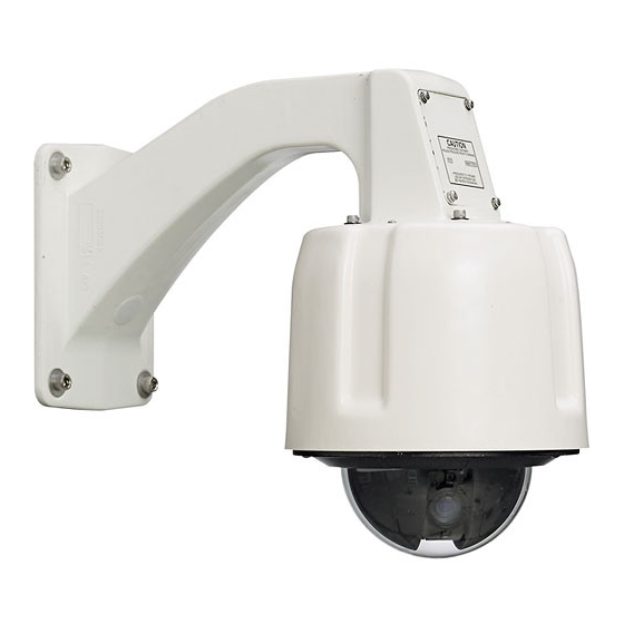
SVFT-PRS Pressurized Dome Housing
Vicon Industries Inc. does not warrant that the functions contained in this equipment will meet
your requirements or that the operation will be entirely error free or perform precisely as
described in the documentation. This system has not been designed to be used in life-critical
situations and must not be used for this purpose.
Copyright © 2006 Vicon Industries Inc. All rights reserved.
Product specifications subject to change without notice.
Vicon and its logo are registered trademarks of Vicon Industries Inc.
VICON INDUSTRIES INC., 89 ARKAY DRIVE, HAUPPAUGE, NEW YORK 11788
TEL: 631-952-CCTV (2288) FAX: 631-951-CCTV (2288) TOLL FREE: 800-645-9116
24-Hour Technical Support: 800-34-VICON (800-348-4266)
UK: +44(0) 1489-566300 WEB: www.vicon-cctv.com
Vicon Part No. 8009-8163-11-00
Section 3 Rev 1006
Advertisement
Table of Contents

Subscribe to Our Youtube Channel
Related Manuals for Vicon SVFT-PRS22E


Summary of Contents for Vicon SVFT-PRS22E
- Page 1 XX163-11-00 SVFT-PRS Pressurized Dome Housing Vicon Industries Inc. does not warrant that the functions contained in this equipment will meet your requirements or that the operation will be entirely error free or perform precisely as described in the documentation. This system has not been designed to be used in life-critical situations and must not be used for this purpose.
-
Page 3: Important Safeguards
20. Replacement Parts - Use only Vicon specified replacement 6. Attachments - Use only UL listed Vicon recommended parts or an approved equivalent to prevent unit damage and injury. -
Page 4: Fcc Notice
FCC Notice Note: Complies with Federal Communications Commission Rules & Regulations Part 15, Subpart B for a Class A digital device. WARNING This equipment generates and uses radio frequency energy and if not installed and used properly, that is, in strict accordance with the manufacturer’s instruction, may cause interference to radio and television reception. -
Page 5: Table Of Contents
Care and Cleaning of Clear Acrylic Domes......................... 27 Fuse Replacement ................................ 27 SHIPPING INSTRUCTIONS ............................... 28 CABLE RECOMMENDATIONS ............................29 Coaxial Cable................................. 29 Twisted-Pair Cable ................................ 30 TECHNICAL INFORMATION ............................. 32 VICON STANDARD EQUIPMENT WARRANTY........................ 37 Contents • iii XX163-11-00 Rev 1006 SVFT-PRS Pressurized Dome Housing... -
Page 6: Quick Installation
Quick Installation iv • Quick Installation XX163-11-00 Rev 1006 SVFT-PRS Pressurized Dome Housing... -
Page 7: Introduction
Open the carton and inspect the equipment for damage. Save the carton and packing material. If damage is present, contact the carrier and file a damage claim immediately. If the equipment must be returned to Vicon for repair, follow the instructions in the Shipping Information section of this manual. - Page 8 Model Product Description Code PRESSURIZED, COLOR CAMERA DOME SYSTEM: includes variable-speed SVFT-PRS22E/ 8768-00/ drive, 22X high-resolution color camera/lens with ExView™ technology, outdoor SVFT-PRS22EC 8768-01 with clear lower dome, coaxial output, NTSC/PAL PRESSURIZED, COLOR CAMERA DOME SYSTEM: includes variable-speed SVFT-PRS23/ 8769-00/...
-
Page 9: Pressurized Housing Components
Pressurized Housing Components The SurveyorVFT Pressurized Housing is comprised of a Housing, a SurveyorVFT Camera Drive and a Trim Ring/Lower Dome Assembly as shown in Figure 1. This assembly is the heart of every prepackaged pressurized housing version of the SurveyorVFT Camera Dome. With the addition of a mount, the pressurized housing version can be equipped for indoor or outdoor wall mount or pipe mounting. -
Page 10: Installation
Use the applicable sub-section to install the correct connector type included. Wall Mount Method Use this method to install, wire and configure a unit with a Vicon wall mount. Refer to Figure 2. Installing the Wall Mount 1. -
Page 11: Installing The 23-Pin Connector Assembly
Installing the 23-Pin Connector Assembly (If the prefabricated 23-pin cable assembly is used) 6. Use the 23-pin cable assembly purchased separately. It should resemble assembly Figure 3. a. Identify the cables required for attaching to the 23-pin connector assembly. There should be a minimum of three (3), power (18 to 32 VAC), control (RS-422/485) -
Page 12: Wiring And Assembling The 23-Pin Connector
Wiring and Assembling the 23-Pin Connector (Using the discrete 23-pin connector with crimp pins provided) 7. Assemble the 23-pin connector as shown in Figure 4. a. Identify the cables required for attaching to the 23-pin connector. There should be a minimum of three (3), power (18 to 32 VAC), control (RS-422/485) and video (RG-59 or twisted... - Page 13 g. Insert each labeled crimp connector into its respective labeled 23-pin connector position (A, B, C, D, etc.). Verify that each is firmly seated. h. Pull the strain relief fitting back up the cable and screw it firmly into the base of the 23-pin connector assembly.
-
Page 14: Preparing The Camera Drive
64 - OFF, 128 - OFF DIP SWITCH S2 typical configuration: 1 - ON (NTSC), 2 - OFF (Serial), 3 - OFF (DUPLEX), 4 - OFF (RS-422), 5 through 8 - OFF (Vicon VPS) 8 • Installation XX163-11-00 Rev 1006 SVFT-PRS Pressurized Dome Housing... -
Page 15: Pressurizing The Housing Assembly
20. Attach the housing’s safety clip to the camera drive’s tab. Tilt the camera drive down and orient the two (2) slots on the housing with the two (2) tabs on the drive and raise it until two distinct clicks are heard. The housing is now securely installed. - Page 16 10 • Installation XX163-11-00 Rev 1006 SVFT-PRS Pressurized Dome Housing...
-
Page 17: Pipe Mount Method
Pipe Mount Method Use this method to install, wire and configure a pipe mounted unit. Refer to Figure 6. Installing the Pipe Mount 1. Select a suitable mounting location and verify that the site wiring is present. Caution: Mount only to installed pipes with sufficient strength to support the mount and unit and as vertically level as possible. -
Page 18: Installing The 23-Pin Connector Assembly
Installing the 23-Pin Connector Assembly (If the prefabricated 23-pin cable assembly is used) 6. Use the 23-pin cable assembly purchased separately. It should resemble assembly Figure 7. a. Identify the cables required for attaching to the 23-pin connector assembly. There should be a minimum of three (3), power (18 to 32 VAC), control (RS-422/485) -
Page 19: Wiring And Assembling The 23-Pin Connector
Wiring and Assembling the 23-Pin Connector (If the discrete 23-pin connector with crimp pins was provided) 7. Assemble the 23-pin connector as shown in Figure 8. a. Identify the cables required for attaching to the 23-pin connector. There should be a minimum of three (3), power (18 to 32 VAC), control (RS-422/485) and... - Page 20 g. Insert each labeled crimp connector into its respective labeled 23-pin connector position (A, B, C, D, etc.). Verify that each is firmly seated. h. Pull the strain relief fitting back up the cable and screw it firmly into the base of the 23-pin connector assembly.
-
Page 21: Preparing The Camera Drive
64 - OFF, 128 - OFF DIP SWITCH S2 typical configuration: 1 - ON (NTSC), 2 - OFF (Serial), 3 - OFF (DUPLEX), 4 - OFF (RS-422), 5 through 8 - OFF (Vicon VPS) Installation • 15 XX163-11-00 Rev 1006 SVFT-PRS Pressurized Dome Housing... -
Page 22: Pressurizing The Housing Assembly
20. Attach the housing’s safety clip to the camera drive’s tab. Tilt the camera drive down and orient the two (2) slots on the housing with the two (2) tabs on the drive and raise it until two distinct clicks are heard. The housing is now securely installed. - Page 23 Warning: Do not use any gas type other than dry Nitrogen. The use of Shop Air can introduce moisture into the housing assembly that can damage it over time. Installation • 17 XX163-11-00 Rev 1006 SVFT-PRS Pressurized Dome Housing...
-
Page 24: Operation
Configuring the ViconNet (IP/LAN) Version The following information is provided when installing the ViconNet version of the SVFT-PRS (IP dome) only. The SVFT-PRS camera dome (IP version) is shipped with a CD that contains the ViconNet version 3 software needed to setup your IP system, including the application setup, the camera firmware and setup software (VNSetup). - Page 25 Using the VNSetup Utility VNSetup consists of several TABs. Each TAB provides different functionalities. Note: Once the VNSetup is run the first time, a shortcut is placed on the desktop for future use. Make sure the MAC address and password of the camera is available. Use MAC Address log provided. Verify that the camera is physically connected to the configuring workstation via the network.
- Page 26 3.2. Nucleus authentication - On the Nucleus login field, enter a valid Nucleus IP address and password and press the Login button. Once approved, notice that the icon has disappeared from all the units currently connected to the selected Nucleus and the user may proceed to next phase.
- Page 27 Install TAB The Install TAB allows the user to install/upgrade newer versions. Install Info Tab The Info TAB displays the selected IP product general information/ Info Installation • 21 XX163-11-00 Rev 1006 SVFT-PRS Pressurized Dome Housing...
- Page 28 Advanced TAB The Advanced TAB functionalities allow the user to handle unexpected events on a specific remote unit when they occur. When a problem occurs, the user can choose to Unjam unit to restart the unit’s firmware, Restart unit to restart the hardware, Net defaults to return the initial network settings and Factory defaults to return to the initial configuration.
-
Page 29: Viconnet Configuration
ViconNet Configuration After the camera dome has been setup with the proper IP address, configuration features from a remote workstation, server or recorder are available as follows. • A network settings screen is used to modify the camera dome’s IP parameters. This allows great flexibility in network setup. - Page 30 ViconNet (IP/LAN) Version Operation The following functions are supported by the ViconNet system through a workstation, recorder or server. 1. System macros can be configured to view and record the dome’s video. In addition, within macros, alarms can be sent and remote macros triggered. 2.
-
Page 32: Troubleshooting
Operation When power is applied to the camera, the SVFT-PRS will boot up through a diagnostic routine and view the currently selected scene. Refer to the latest version of the SurveyorVFT Programming Manual XX134-40 for details on setup and operation. Troubleshooting If the SurveyorVFT does not power-up correctly, check the following: ⇒... -
Page 33: Maintenance
Maintenance The SVFT-PRS Camera Dome requires no scheduled maintenance except for the occasional cleaning of the lower dome. Care and Cleaning of Clear Polycarbonate Domes 1. Always handle the lower dome by the flange and avoid touching the inside surface. 2. -
Page 34: Shipping Instructions
Shipping Instructions Use the following procedure when returning a unit to the factory: 1. Call or write Vicon for a Return Authorization (R.A.) at one of the locations listed below. Record the name of the Vicon employee who issued the R.A. -
Page 35: Cable Recommendations
Cable Recommendations Coaxial Cable Caution: Careful selection of proper cable is essential to obtain the best performance from this equipment. Vicon assumes no responsibility for poor performance when cables other than those recommended, or equivalent, are installed. In all cases, coaxial cable impedance should be 75 ohms. -
Page 36: Twisted-Pair Cable
Twisted-Pair Cable CAUTION: Careful selection of the proper cable is essential to obtain the best performance from this equipment. Vicon assumes no responsibility for poor performance when cables other than those recommended are installed. Materials Use a pure copper stranded conductor with or without a tin plating to obtain a low DC resistance. Do not use cable with either a steel or an aluminum stranded conductor because these do not transfer signals effectively for long distances. -
Page 37: Network Cable
Network Cable Caution: Careful selection of proper cable is essential to obtain the best performance. Vicon assumes no responsibility for poor performance when cables other than the recommended types, or equivalent, are used. Materials Use pure copper stranded conductors to obtain a low DC resistance. The preferred insulation and cable jacket is Polyvinyl chloride (PVC). -
Page 38: Technical Information
Technical Information ELECTRICAL Drive Type: Electrical motorized pan and tilt, electronic control. Camera Types: Units available in color and day/night (NTSC/PAL) formats and a variety of zoom and feature capabilities. Input Voltage: 18-30 VAC. (Will operate within spec on voltages up to 32 VAC. - Page 39 OPERATIONAL (SurveyorVFT Camera Drive only) Video Pan View: 360°. Video Tilt View: -2.5° (-2.5° above horizon) to 92.5° (-2.5° past vertical). Pan Speed: Variable, 0.1 - 360°/sec. Autopan Speed: Variable, 0.1 - 42°/sec, enable/disable. Tilt Speed: Variable, 0.1 - 150°/sec. Zoom and Focus Speed: Less than 1.8 sec from end to end.
- Page 40 Screen Titling Capabilities: Programmable for camera, preset, sector, relay and alarms. Camera: 1 for each. Preset: 79 maximum. Sector: 16 maximum. Alarm: 4 maximum. Individual type date and time enable/disable; 20 characters maximum. Selectable position. Three text sizes for top two lines.
- Page 41 Available Versions: Video Zoom: 22EX optical, 12X digital, 264X total. 23X optical, 12X digital, 276X total. 25X optical, 12X digital, 420X total. Video Output and Control: Coaxial output, RS-422/RS-485 control. UTP output, RS-422/RS-485 control. Fiber Optic output, Fiber Optic control. LAN output, LAN control.
- Page 42 Operating Pressure: 1 - 5 psi (0.07 - 0.34 atm or bars) maximum. Pressurization: Schraeder type valve used to fill and drain housing with dry nitrogen gas. Relief valve automatically relieves pressure at 5 - 7 psi (0.34 - 0.48 atm). Pressurization Volume: 0.28 ft (0.008 m...
-
Page 43: Vicon Standard Equipment Warranty • 37
Software supplied either separately or in hardware is furnished on an “As Is” basis. Vicon does not warrant that such software shall be error (bug) free. Software support via telephone, if provided at no cost, may be discontinued at any time without notice at Vicon’s sole discretion. - Page 44 Vicon Industries Inc. Corporate Headquarters 89 Arkay Drive Hauppauge, New York 11788 631-952-CCTV (2288) 800-645-9116 Fax: 631-951-CCTV (2288) Vicon Europe Headquarters Brunel Way Fareham, PO15 5TX United Kingdom +44(0) 1489/566300 Fax: +44(0) 1489/566322 Brussels Office Planet II - Unit E...
Need help?
Do you have a question about the SVFT-PRS22E and is the answer not in the manual?
Questions and answers