Table of Contents
Advertisement
Quick Links
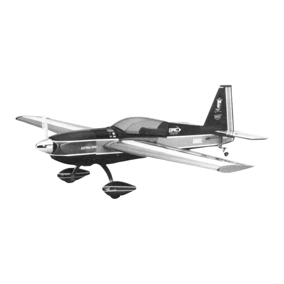
ALMOST READY-TO-FLY RADIO CONTROLLED MODEL AIRPLANE
•
SUPERIOR QUALITY IN AN ALMOST-READY-TO-FLY MODEL.
•
SPECIAL COVERING PROCESS YIELDS A STRONG, BRILLANT, AND FUEL-PROOF
FINISH.
•
80% COMPLETE OUT OF THE BOX - NO SANDING, PAINTING, OR FINISHING REQUIRED
•
WORLD CLASS AEROBATIC CAPABILITIES, JUST LIKE THE REAL EXTRA 300.
•
BEAUTIFUL SEMI SCALE APPERANCE.
WINGSPAN: 553/4"
LENGTH: 44 1/2"
WING AREA: 543sq.in.
WEIGHT: 91-95 oz.
ENTIRE CONTENTS © 1990,
RADIO: 4-Channel (Not Included)
ENGINE:
.46 Performance 2-Cycle (Not Included)
or 60-70 4-Cycle (Not Included)
ACCESSORIES: Starting Battery w/Clip, Fuel Etc. (Not Included)
V1.0 INC.
Advertisement
Table of Contents

Related Manuals for Hobbico Extra 300


Summary of Contents for Hobbico Extra 300
- Page 1 SPECIAL COVERING PROCESS YIELDS A STRONG, BRILLANT, AND FUEL-PROOF FINISH. • 80% COMPLETE OUT OF THE BOX - NO SANDING, PAINTING, OR FINISHING REQUIRED • WORLD CLASS AEROBATIC CAPABILITIES, JUST LIKE THE REAL EXTRA 300. • BEAUTIFUL SEMI SCALE APPERANCE. WINGSPAN: 553/4" LENGTH: 44 1/2"...
-
Page 2: Important: Before You Begin
If the Extra 300 is not quite what you expected, return it to your dealer in New and Unused condition. However, we think you will agree with us that the Extra 300 kit is one of the finest models of its type and will offer you many hours of enjoyment. -
Page 3: Parts List
PARTS LIST Control Rods Before assembly, match the parts Throttle Control Rod (Long) in the exploded view of the Extra Throttle Tube 300 with the parts in the kit. Check Wood Push Rods Plastic Disc (Red) off each part on the parts list. If any Main Servo Tray parts are missing or damaged Stabilizer Supports... -
Page 4: Wing Assembly
WING ASSEMBLY Remove the foam covering from the aileron servo mounting area Wing Mounting Brace....1 A. Right Wing (Aileron Installed) ..1 from the top side of the wing. Test fit the main wing joiner and the B. Left Wing (Aileron Installed)..1 J. - Page 5 Drill two 8mm (5/16") holes into the wing joiners for the dowel After the joiners have cured, apply epoxy where shown. The wing rods. Drill through the front joiner and into the rear wing joiner. roots, the wing joiners should be evenly and liberally covered with epoxy.
- Page 6 15. Screw in the wing bolts into the wing bolt mounting block so that the Epoxy in the main servo tray as shown. heads are 1/4" above the block. Apply ink or paint to the heads of the two bolts. 16.
-
Page 7: Landing Gear Installation
LANDING GEAR INSTALLATION 18. Drill two 4mm holes 90' from the top wing surface for the wing bolts A. MainGear........1 H Wheel Pants.......2 where the paint marks are. B. Rubber Shock Absorber....1 4mm x 40mm Screw ....2 4mm x 30mm Screw ....2 3mm x 12mm Screw ....2 D. - Page 8 Arrange the above parts as shown and then assemble together. Do Thread two 4mm nuts onto the two screws and tighten Next place this twice. Place thread lock on the threads when installing the nuts the rubber shock absorber over the screws. Place the 3mm screw/washer into the top hole of the wheel pants Now place the main gear over the screws and secure it with two 4mm from the inside And then attach it to the top hole of the main gear...
-
Page 9: Engine Installation
Install the two mounting plates onto the engine mount. Next, paint Make sure that both wheels rotate freely. If they do not, trim away a strip on each plate using four 4mm x 15mm screws and washers the plastic as needed. Or if need be, loosen the nuts and reposition the wheel. - Page 10 ENGINE INSTALLATION Mount the plates to the engine using the 3.5mm screws up from the bottom as shown. Next apply screw locking compound to the screw Fuel Tank................... 1 threads and tighten on the 3.5mm nuts with lock washers. Do this Clunk ..................1 to both sides.
- Page 11 Put a bead of silicone sealer on the neoprene ring. Carefully bend up the other fuel pipe so it will just touch the inside top of the fuel tank. 7. Install the fuel tank from the inside of the fuselage with the fuel lines Attach the complete fuel tank cap to the tank.
-
Page 12: Radio Installation
RADIO INSTALLATION F. Throttle Control Rod (Long)..1 A. Aileron Horn......... 2 Screw two snap clevises half way up the threads on the aileron G. SnapClevis......... 2 control rods. Next, cut two pieces of the clevis retaining tubing B. Wood Push Rods......2 H. - Page 13 RADIO INSTALLATION Locate two rod clevises from the plastic parts tree. Trial fit the servos into the fuselage servo tray, and trim the tray as needed for a good fit. 10. Install the three remaining servos (1/4" apart) into the tray using Attach the rods to the servo arm using the rod clevis.
- Page 14 15. Cut four equal pieces of the white shrink tubing (about 2" each) 12. Assemble the rudder and elevator control rods using the parts above. 16. Assemble the elevator push rod as shown. Place the two elevator 13. Bend two of the long rods as shown for the elevator and one of the rods into the double grooved end of one of the rods.
- Page 15 21. Use the throttle control rod and the white throttle tube for the engine 18. Punch out the three rod exits at the tail and insert the rudder pu sh rod linkage. Lightly sand the plastic tube so the epoxy will adhere to it. into the fuselage from the front and then through the bottom exit on Cut the plastic tube so it is only 12"...
- Page 16 27. From the inside, pull back the throttle control rod so the carburetor 24. Connect the servos to the receiver and battery and center all radio controls (including the throttle stick and move the servo horns so is closed. Now, mark the rod where it crosses the throttle servo horn they are in line with the servo as shown.
- Page 17 Install the main wing. Next place the horizontal stabilizer onto the NOTE: The tail wheel parts M-T may vary due to an updated design. tail. Hold it on and visually see if the wing and stabilizer are parallel. See page 18, Step 10. If not, sand the higher side of the stabilizer mount until! the stabilizer Tail Wheel........
- Page 18 9. When satisfied with the fairing positioning, apply cyanoacrylate glue Once the horizontal stabilizer epoxy has cured, trial fit the vertical fin to the underside edge of the stabilizer cover and install in place (without the rudder) on top of the horizontal stabilizer and the back edge is even with the rear of the fuselage.
- Page 19 12. Now take the supports and bend the ends as shown above. 15. Install the tail wheel assembly through the metal strip. Next, trail fit the rudder onto the vertical fin. Notice where the bottom hinge meets the fuselage and make a slot in the tail where the rudder hinge needs to be with an X-Acto knife.
- Page 20 Glue (using PlastiZap) the rectangular mounting plates to the rudder 18. Place a small amount of epoxy on the hinges, in the groove, and on the end of the tail control arm. (It is a good idea to place some so that they are centered, one on each side, over the tail control arm petroleum jelly onto the hinge center joint (point of movement) to that is "inside"...
- Page 21 Cut the clevis retaining tube so that you have three 3/16" tubes Drill six 3mm holes for the three horns Make sure that you drill straight through to the other side Slide on one of the retaining tubes onto each rod Screw on the Install the six brass tubes into the holes plastic snap clevises to the three push rods coming out of the fuselage Screw them on half way up the threads...
- Page 22 COWL AND PROP INSTALLATION Align the rods over the servo horns and make a mark where they intersect Make sure that the control surfaces are in neutral (center Cowl (4 piece)................1 position) before marking. Cowl Brace ................1 3mm x 10mm Self-Tapping Screw ..........3 Spinner ..................1 Spinner Back Plate ....
- Page 23 6. Apply the 1/4" white striping tape to the seams on the outside of the Epoxy the cowl brace onto the front of the fuselage. Make sure that cowl. the beveled ends angle down in line with the fuselage. Attach the muffler to the engine if using a two cycle.
-
Page 24: Receiver And Battery Installation
Install the battery first into the front of the fuselage as shown and Reposition the cowl and drill a 2mm hole at each point and attach the then install the receiver on top. cowl using three 3mm x 8mm self-tapping screws. If using a 4-Cycle engine, install the muffler/pipe at this time. - Page 25 Apply the red sthpes to the side of the cockpit and trim as shown. Epoxy the four cockpit mounts to the fuselage as shown. Be careful Apply the "Extra 300" decals to the cowl sides. when gluing the rear mounts to only glue them to the wing mounting brace.
-
Page 26: Center Of Gravity
SERVO THROWS CENTER OF GRAVITY Balance the plane using the mark on the side of the fuselage. It should The amount of throw that the control surfaces have is critical if you want balance at this point See below. a properly responsive plane Measure the throws as shown above They should be. -
Page 27: Starting Engine
STARTING ENGINE Engine Maintenance Turn the radio on and open the throttle to full open Place your finger Always check the engine mounting bolts, muffler, glow plug, propeller and over the air intake on the carburetor while turning the prop counter spinner, etc .before attempting to start the engine Check for loose bolts, nuts or screws which may come off when the engine is running and cause clockwise a few times Notice the fuel line If no fuel is reaching the... - Page 28 On the ground, the Fully Assembled Extra 300 rudder is more effective A transition will need to be made once the plane...
Need help?
Do you have a question about the Extra 300 and is the answer not in the manual?
Questions and answers