Table of Contents
Advertisement
Quick Links
Installation and Operating Instructions
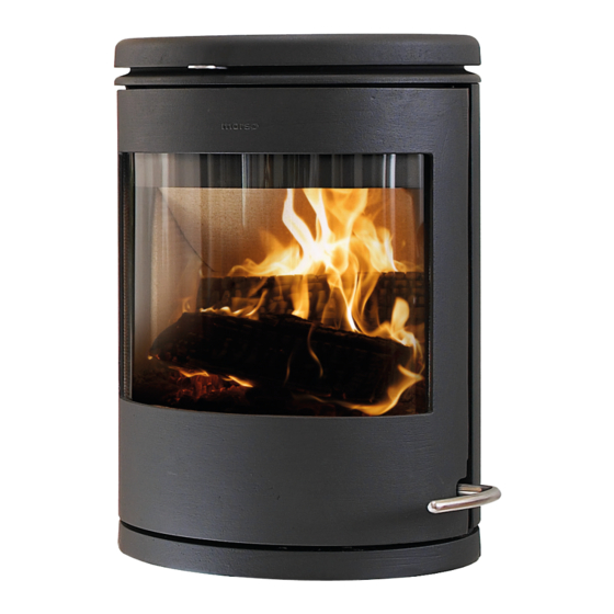
7670
For use in North America
Read this entire manual before you install and use your new room heater. If this room
heater is not properly installed, a house fire may result. To reduce the risk of fire, follow
the installation instructions. Failure to follow instructions may result in property damage,
bodily injury, or even death.
Contact local building officials about restrictions and installation/inspection-requirements
in your area.
Save these instructions
MORSØ JERNSTØBERI A/S . DK-7900 NYKØBING MORS
E-Mail: stoves@morsoe.com · Website: www.morsoe.com
Distributed by: MORSO US LLC
1
1011 Highway 52 West - Portland TN - 37148 - USA
Advertisement
Table of Contents

Related Manuals for Morso 7670


Summary of Contents for Morso 7670
-
Page 1: Installation And Operating Instructions
Contact local building officials about restrictions and installation/inspection-requirements in your area. Save these instructions MORSØ JERNSTØBERI A/S . DK-7900 NYKØBING MORS E-Mail: stoves@morsoe.com · Website: www.morsoe.com Distributed by: MORSO US LLC 1011 Highway 52 West - Portland TN - 37148 - USA... - Page 2 The Morsø 7670 meets the U.S. Environmental Protection Agency’s emission limits for wood heaters sold on or after July 1, 1990. The Morsø 7670 have been tested by OMNI-Test Laboratories, Inc. The test standards are ANSI/UL-1482 for the United States and ULC S627 for Canada.
-
Page 3: Table Of Contents
CONTENTS: Installation of your Morsø stove Checking loose parts in the stove The chimney / flue system Flue Connection Connection to existing chimney Positioning the stove Operation Before you start firing Lighting and loading intervals Maintenance Exterior maintenance Internal maintenance Cleaning the stove and the flue Leaving the stove for extended periods Parts diagram... -
Page 4: Installation Of Your Morsø Stove
1.0 Installation of your Morsø stove Installation of woodburning stoves must be safe and legal. Consult with a structural engineer for the installation. The stove must be installed on a non-combustible wall. If your Morsø stove is not installed correctly, it may cause a house fire. To reduce the risk of fire, the installation instructions must be followed carefully. -
Page 5: The Chimney / Flue System
1.2 The chimney / flue system Note that the flue system must be independently secured and must not rely on the stove for support. The stove must not be connected to a chimney flue serving any other appliance. (Several flues may run up a single chimney stack; use one flueway per appliance). Use a residential type masonry or listed type HT factory-built chimney. -
Page 6: Flue Connection
1.3 Flue Connection The stove is supplied from the factory with a round blanking plate blocking off the top and rear flue exit (behind the rear shield plate). A flue collar are placed in the firebox area. Use a 24 MSG black or blue chimney connector or listed double wall chimney connector. Refer to local codes and the chimney manufacturer’s instructions for precautions required for passing a chimney through a combustible wall or ceiling. -
Page 8: Positioning The Stove
1.5 Positioning the stove The stove must be installed on a non- combustible wall. The wall-mounting fixture is provided with four holes for mounting expansion bolts in the wall. The bolts must be sized to secure that the wall and the materials it is made from are capable of supporting the stove. - Page 9 CLEARANCE REQUIREMENTS STANDARD RESIDENTIAL INSTALLATION INTEGRAL REAR AND BOTTOM SHIELDS TOP OR REAR VENT SINGLE OR DOUBLEWALL CONNECTOR CANADA 15’’ 381 mm. SIDEWALL TO UNIT 1’’ 25 mm. BACKWALL TO UNIT 2,5’’ 64 mm. CORNERWALL TO UNIT 21’’ 533 mm. SIDEWALL TO CONNECTOR 7’’...
- Page 10 FLOOR PROTECTION REQUIREMENTS NON-COMBUSTIBLE MATERIALS BENEATH STOVE CANADA EXTENDING DISTANCE, BACK 200 mm. EXTENDING DISTANCE, RIGHT SIDE 6’’ 200 mm. EXTENDING DISTANCE, LEFT SIDE 6’’ 200 mm. EXTENDING DISTANCE, FRONT 16’’ 450 mm. Distance to furniture The recommended minimum distance from stove to furniture is 30 inches. Note that some furniture is more easily affected by heat and may need to be moved to a greater distance.
-
Page 11: Operation
2.0 Operation 2.1 Before you start firing For Use with Solid Wood Fuel Only. Do Not Overfire, If Heater or Chimney Connector Glows You Are Overfiring. Inspect and Clean Chimney Frequently. Under Certain Conditions of use creosote buildup may occur rapidly. Because of risk of smoke and flame spillage, operate only with door fully closed. -
Page 12: Lighting And Loading Intervals
The secondary air is injected into the flue gases above the fire resulting in a cleaner, more efficient combustion process. The supply of secondary air and Pilot air is fixed open and is not adjustable. For extra safety, your stove should be with a removable handle. 2.2 Lighting and loading intervals When first lighting the stove, a large volume of air is needed. - Page 13 5. If the condition in step 4 is met, place max. 2 pieces of wood with a total weight of 1.5-2 kg and a length of 25- 30 cm over the embers in a single layer, with a distance of approximately 1 cm.
- Page 14 Do not for any reason attempt to increase the firing of your heater by altering the air control adjustment range outlined in these directions. Warning: Fireplace stoves must never be left unattended with the door open. If the door is left partly open, gas and flame may be drawn out of the fireplace stove opening, creating risks from both fire and smoke.
-
Page 15: Maintenance
3.0 MAINTENANCE When perfoming maintenance on your stove, always protect yourself, using safety goggles and gloves. 3.1 Exterior Maintenance The stove surface is painted with heat-resistant Senotherm paint. It is best kept clean by vacuuming with a soft brush attachment or by wiping with a lint-free cloth. Over a period of time, the painted surface may become slightly grey. - Page 16 1. When you open the door, you will find two hinge pins, one in each hinge. Remove the two hinge pins, lift the door off the hinges and place it face down on a sheet of cardboard or other nonabrasive fabric. 2.
-
Page 17: Cleaning The Stove And The Flue
3.3 Cleaning the Stove and the Flue Check for soot above the baffle plate and around the flue outlet every month or so to start with. If the stove suddenly becomes sluggish, check for a soot fall around the flue collar or in the flue/chimney. - Page 18 Check the glass for cracking; replace if needed. Check door and handle for tightness. Adjust if needed. How to clean the inside parts of Morsø 7670 When cleaning the inside parts of the stove in connection with the annual visits from your local chimney sweep we recommend that you remove the inside parts from the fire chamber.
-
Page 19: Leaving The Stove For Extended Periods
3.4 Leaving the stove for extended periods Important: If the stove is to be left unused for any period of time, clean it out thoroughly and leave the air control slightly open to allow airflow. Make sure that the flue does not allow rainwater to come anywhere near the stove;... -
Page 20: Parts Diagram
3.5 Parts diagram for model Morsø 7670... -
Page 22: Parts List
3.6 Parts list for model Morsø 7670 Pos.Nr.: Parts: 7670 NA Base plate 447150xx Top frame 447607xx Door 447603xx Front frame 447656xx Rear plate, outside 447652xx Top plate, outside 447611xx Rear plate, inside 44765100 Side plate, inside, right 447606xx Side plate, inside, left... - Page 23 Pos.Nr.: Parts: 7670 NA Screw 73861000 Baffle plate, top 71761700 Distance tube 54143700 Cover 442610xx 545006 Distance tube 545007 Plug f. Door 71760700 Fittig f. Door 71760600 Fitting f. Handle 71761100 Fitting for Flue Collar 44256700 Pedestal Fittig f. Door 71762400 Foot, f.
- Page 24 Morsø jernstøberi A/S 09-03 -2012 72761600...
Need help?
Do you have a question about the 7670 and is the answer not in the manual?
Questions and answers