Table of Contents
Advertisement
®
User Manual
TM
Universal Programmable
Wireless Thermostat Kit
For Systems Up to 3 Heat / 2 Cool
7500
See Wireless Setup Guide for Wireless Setup Instructions
Read all instructions before proceeding
Store this manual for future reference
7500-110-01
©2015 Braeburn Systems LLC • All Rights Reserved • Made in China.
Advertisement
Table of Contents

Related Manuals for Braeburn 7500


Summary of Contents for Braeburn 7500
-
Page 1: User Manual
For Systems Up to 3 Heat / 2 Cool 7500 See Wireless Setup Guide for Wireless Setup Instructions Read all instructions before proceeding Store this manual for future reference 7500-110-01 ©2015 Braeburn Systems LLC • All Rights Reserved • Made in China. -
Page 2: Table Of Contents
Contents 1 About Your Wireless Thermostat Kit 4 Operating Your Thermostat Thermostat Features ..........3 Setting the System Control Mode ......22 Thermostat and Display ........... 4 Setting the Fan Control Mode ....... 23 Control Module ............8 Setting the Temperature ........24 Status Indicators .......... -
Page 3: About Your Wireless Thermostat Kit Thermostat Features
Congratulations! You are in control of one of the easiest-to-use wireless thermostats on the market today. This thermostat has been designed to provide you with years of reliable performance and comfort control. Features • Reliable BlueLink Smart Connect wireless technology •... - Page 4 1 About Your Thermostat HUMID BACK NEXT User Manual...
-
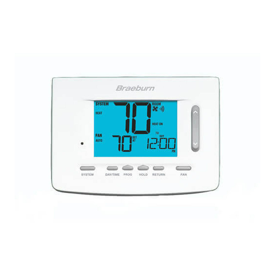
Page 5: Thermostat And Display
Thermostat Display Room Temperature ...... Displays the current room temperature Set Temperature ......Displays the current set point temperature Outdoor Temperature Indicator ... Displays along with the outdoor temperature reading** BACK Indicator* ......BACK button is active NEXT Indicator*......NEXT button is active Humidity Indicator ..... - Page 6 1 About Your Thermostat INSTRUCTIONS BACK NEXT DAY/TIME User Manual...
- Page 7 ® temperature by pressing the PROG and HOLD buttons at the same time. Humidity Setpoint ......If a Braeburn wireless humidity sensor is connected you can view the current humidity or make adjustments to the humidity setpoint by pressing the DAY/TIME and RETURN buttons at the same time.
-
Page 8: Control Module
Control Module Your thermostat communicates wirelessly with a control module installed on or near your heating/cooling equipment. This control module is wired directly to your equipment. NOTE: There is a return air sensor connected to the control module to maintain default temperature control should the batteries ever become drained in the thermostat. -
Page 9: Setting User Options
2 Setting User Options INSTRUCTIONS Advanced User Options User options allow you to customize some of your INSTRUCTIONS thermostat’s features. Most users will not need to make any changes to the settings in this section. To access the User Options menu, press and hold the RETURN button for 3 seconds until the screen changes and displays the first User Option. -
Page 10: Table Of User Options
Table of User Options NOTE: Some user options may not be available, depending on how your thermostat was configured in the Installer Settings (see Installer Manual). A detailed description of each User Option follows this table. No. User Options Factory Setting Comments Default... -
Page 11: Service Monitors (Filter, Uv And Humidifier Pad)
Service Monitors (Filter, UV and Humidifier Pad) User Options 1, 2 and 3 There are three user selectable service monitors that will display reminders for a required air filter, UV bulb or humidifier pad replacement. The SERVICE segment flashes in the display along with FILTER, UV or HUMID. -
Page 12: Temporary Override Adjustment Limit
Temporary Override Adjustment Limit User Option 5 The Temporary Override Adjustment Limit will limit how much the temperature can be adjusted from the current set point when the thermostat is used in the programmable mode. This setting will not allow the user to override the temperature past the selected limit amount of 1, 2 or 3 degrees from the current set point. -
Page 13: Setting Your Program Schedule
3 Setting Your Program Schedule Setting the Time and Day 1. In normal operating mode, press the DAY/TIME button. The display will switch to the day/time setting mode and the hour will be flashing. 2. Press the SpeedBar up or down to adjust the ®... -
Page 14: Tips Before Setting Your Program Schedule
Tips Before Setting Your Program Schedule • Make sure your current time and day of the week are set correctly. • When programming, make sure the AM and PM indicators are correct. • Various installer settings such as auto changeover mode and temperature adjustment limits may affect your programming flexibility. -
Page 15: Energy Saving Programs
Energy Saving Programs This thermostat comes pre-programmed with a default energy saving program. The following tables outline the pre-programmed times and temperatures for heating and cooling in each of your 4 daily events (2 events if configured for commercial mode). If you wish to use these settings then no further programming is necessary: Residential 7 Day Programming Commercial 2 Event Programming Factory Settings... - Page 16 Residential 5-2 Day Programming– Weekday/Weekend Factory Settings 4 Event Time: 6:00 am Time: 6:00 am Heat: 70˚ F (21˚ C) Heat: 70˚ F (21˚ C) Cool: 78˚ F (26˚ C) Cool: 78˚ F (26˚ C) Time: 8:00 am Time: 8:00 am Heat: 62˚...
-
Page 17: Programming A 7 Day Residential Schedule
Programming a 7 Day Residential Schedule The 7 day residential programming mode gives you the option to program individual days (1 day at a time) or to use SpeedSet and program the entire week (all 7 days) with a 4 event program schedule. Setting All 7 Days at Once (SpeedSet ®... - Page 18 Setting Individual Days (7 Day Residential) 1. Press the PROG button. The display will switch to programming mode. M (Monday) will be displayed and the hour will be flashing. 2. Press SYSTEM to select HEAT or COOL. 3. Press DAY/TIME to select the day you would like to program.
-
Page 19: Programming A 5-2 Day Residential Schedule
Programming a 5-2 Day Residential Schedule The 5-2 day residential programming mode allows you to program Monday - Friday with one 4 event schedule and then allows you to change Saturday and Sunday with a different 4 event schedule. 1. Press the PROG button. The display will switch to programming mode. -
Page 20: Programming A 7 Day Commercial Schedule
Programming a 7 Day Commercial Schedule The 7 day commercial programming mode gives you the option to program individual days (1 day at a time) or to use SpeedSet and program the entire week (all 7 days) with a 2 event program schedule. Setting All 7 Days at Once (SpeedSet ®... - Page 21 Setting Individual Days (7 Day Commercial) 1. Press the PROG button. The display will switch to programming mode. M (Monday) will appear and the hour will flash. 2. Press SYSTEM to select HEAT or COOL. 3. Press DAY/TIME to select an individual day. 4.
-
Page 22: Operating Your Thermostat
4 Operating Your Thermostat Setting the SYSTEM Control Mode The System Control has 5 modes of operation – AUTO, COOL, OFF, HEAT and EMER. The mode can be selected by pressing the SYSTEM button to scroll through the different modes. NOTE: Depending on how your thermostat was configured, some system modes may not be available. -
Page 23: Setting The Fan Control Mode
Setting the FAN Control Mode The Fan Control has 3 modes of operation – AUTO, ON, and PROG. The mode can be selected by pressing the FAN button to scroll through the different modes. NOTE: Depending on how your thermostat was configured, some fan modes may not be available. AUTO The system fan will run only when your heating or cooling system is running. -
Page 24: Setting The Temperature
Setting the Temperature SpeedBar Temporary Adjustment – Press the SpeedBar up or ® down to adjust the current set temperature. If your thermostat is running in 5-2 or 7 day programmable mode, the set temperature will change back to your original programmed settings when your next scheduled change in temperature occurs. -
Page 25: Status Indicators
Status Indicators Status indicators appear in the display to let you know if your system is heating, cooling or off. Status Indicator HEAT ON Heating system is running. COOL ON Cooling system is running. Auxiliary stage of heating is running (multi-stage systems only) EMER Emergency heating system is running... -
Page 26: Communication Loss
Communication Loss If communication with a wireless device has been lost, the display screen will alternate between COMM LOSS and the name of the device that has lost communication. See Table 1 for a list of possible device names. The device will attempt to reconnect with the thermostat automatically, however you can also manually attempt reconnection by pressing and holding the CONNECT button for 3 seconds on the device (see Installer Guide). -
Page 27: Remote Sensor - Low Batteries
Remote Sensor - Low Batteries If batteries become low in a wireless remote sensor, the display screen will alternate between LOW BATT and the name of the sensor that has the low batteries. See Table 2 below for a list of possible sensor names. Replace the batteries in the remote sensor as soon as possible (see wireless remote sensor instructions). -
Page 28: Program Event Indicator
Program Event Indicators Program Event Indicator Program event indicators appear in the display to let you know what part of your current program is active. • In Residential Program Mode, MORN, DAY, EVE or NIGHT will appear. • In Commercial Program Mode, OCCUPIED or UNOCCUPIED will appear. -
Page 29: Additional Operation Features
5 Additional Operation Features Auto Changeover Mode Auto Changeover mode is a feature enabled/ disabled in the Installer Settings (see Installer Guide). If enabled, it is selected by pressing the SYSTEM button until AUTO HEAT or AUTO COOL appears in the display. When Auto Changeover mode is enabled and selected, the system automatically switches between heating and cooling when the room... -
Page 30: Adaptive Recovery Mode
Adaptive Recovery Mode (ARM ™ Adaptive Recovery Mode is a feature enabled/disabled in the Installer Settings (See Installer Manual). If enabled, the feature is automatically present while in programmable mode. Adaptive Recovery Mode tries to reach your desired heating or cooling temperature at the time you have set in your current program schedule, after a setback period. -
Page 31: Programmable Fan Mode
Programmable Fan Mode Programmable Fan Mode is selected by pressing FAN until PROG appears in the display. It is only available in programmable mode. Programmable Fan Mode allows the user to run the fan continuously during a selected program event. To use this feature, select fan ON while setting program events. -
Page 32: Locking And Unlocking The Thermostat
Locking and Unlocking the Thermostat Your 3-digit Lock Code is set in the “User Options” portion of this manual (See “Setting User Options”, page 9 and 12). Once the code is set, the thermostat can be locked or unlocked at any time by entering that code. - Page 33 If you entered a valid code the thermostat will be locked or unlocked (depending on its previous state). When locked, the word LOCKED appears in the display (Figure 1). If an invalid code is entered the word NO will briefly appear, indicating that an incorrect code was entered (Figure 2).
-
Page 34: Ac Power Monitor
Installer Settings (See Installer Guide). If a Braeburn indoor remote sensor was installed and properly configured in the Installer Settings, the thermostat will sense temperature at a remote location or at a combination of a remote location and the thermostat location. -
Page 35: Outdoor Remote Sensing
Braeburn wired or wireless remote outdoor ® sensor. No additional configuration is required. If a Braeburn outdoor remote sensor was installed you may press the PROG and HOLD buttons at the same time to view the outdoor temperature. DAY/TIME... -
Page 36: Humidification And Dehumidification
Humidification and Dehumidification If this thermostat was also equipped with a wireless humidity sensor, it can be used to control a whole house humidifier or dehumidifier. Humidification can be controlled manually from the thermostat or automatically when a outdoor remote sensor is installed and configured in the Installer Settings (See Installer Guide). - Page 37 If humidification and dehumidification are both enabled you will first see the current humidity level along with the humidification set point. Press the SpeedBar up or down to adjust the humidification ® set point. Press DAY/TIME and RETURN again to display the dehumidification set point.
-
Page 38: Thermostat Maintenance
6 Thermostat Maintenance Thermostat Cleaning Never spray any liquid directly on the thermostat. Using a soft damp cloth wipe the outer body of the thermostat. Never use any abrasive cleansers to clean your thermostat. Changing the Batteries This thermostat requires two (2) properly installed “AA” alkaline batteries to maintain the thermostat clock and to provide power for the thermostat if 24 volt AC power is not connected. -
Page 39: Limited Warranty
Limitations apply. For limitations, terms and conditions, you may obtain a full copy of this warranty: LIMITED WARRANT Y · Visit us online: www.braeburnonline.com/warranty · Write us: Braeburn Systems LLC 2215 Cornell Avenue Montgomery, IL 60538 Store this manual for futur e reference. Stor e reference. - Page 40 ® ® Braeburn Systems LLC 2215 Cornell Avenue • Montgomery, IL 60538 Technical Assistance: www.braeburnonline.com 844-BLU-LINK (844-258-5465) (U.S.) 630-844-1968 (Outside the U.S.) 7500-110-01 ©2015 Braeburn Systems LLC • All Rights Reserved • Made in China.
Need help?
Do you have a question about the 7500 and is the answer not in the manual?
Questions and answers
How do you switch from commercial mode to residential mode
To switch the Braeburn 7500 from commercial mode to residential mode, press and hold the "Return" and down arrow buttons at the same time for a few seconds to enter the installer setup menu. The first item shown will be the mode setting. Use the arrow buttons to select "Residential" instead of "Commercial."
This answer is automatically generated