Table of Contents
Advertisement
Programmable Touchscreen Thermostats
6100 Single Stage Heat / Cool Conventional
or Heat Pump
6300 Up to 4 Heat / 2 Cool Heat Pump
Up to 3 Heat / 2 Cool Conventional
6400 Up to 4 Heat / 2 Cool Heat Pump
Up to 3 Heat / 2 Cool Conventional
with Humidity Control
1 Specifications
4 Installer Settings
Attention
To prevent damage to the thermostat, never use a sharp instrument
to press the touchscreen keys. Always press keys with your fingers.
Warning
For installation by experienced service technicians only.
Caution
• Possible electric shock or damage to equipment can occur.
• Disconnect power before beginning installation.
This thermostat requires 24 Volt AC Power or 2 properly installed "AA" Alkaline
batteries for proper operation. When connecting 24 Volt AC Power the batteries may
be installed as a backup.
For use only as described in this manual. Any other use will void warranty.
2 Installation and Wiring
®
Installer Guide
Touchscreen
3 Quick Reference
5 System Testing
TM
Advertisement
Table of Contents

Related Manuals for Braeburn 6100


Summary of Contents for Braeburn 6100
- Page 1 ® Installer Guide Touchscreen Programmable Touchscreen Thermostats 6100 Single Stage Heat / Cool Conventional or Heat Pump 6300 Up to 4 Heat / 2 Cool Heat Pump Up to 3 Heat / 2 Cool Conventional 6400 Up to 4 Heat / 2 Cool Heat Pump...
-
Page 2: Specifications
• AC Power: 18 – 30 Volts AC • DC Power: 3.0 Volt DC (2 “AA” Alkaline Batteries Included) • Control Range: 45° – 90° F (7° – 32° C) • Temperature Accuracy: +/- 1° F (+/- .5° C) • Outdoor Temperature Display Range: -40° - 120° F (-40° - 49° C) Humidification Specifications (6400 Only) • Humidification Control Range: 10% - 50% RH • Dehumidification Control Range: 40% - 80% RH Terminations • 6100: G, Rc, Rh, W, O/B, Y, C, S1, S2 • 6300: A, G, Rc, Rh, W1/E/AUX1, W2/AUX2, W3/O/B, Y1, Y2, C, L, S1, S2 • 6400: H, A/D, G, Rc, Rh, W1/E/AUX1, W2/AUX2, W3/O/B, Y1, Y2, C, L, S1, S2 2 Installation and Wiring Warning Disconnect power before beginning installation. Thermostat Location Install the thermostat approximately 5 feet (1.5m) above the floor in an area that has a good amount of air circulation and maintains an average room temperature. Avoid installation in locations where the thermostat can be affected by drafts, dead air spots, hot or cold air ducts, sunlight, appliances, concealed pipes, chimneys and outside walls. - Page 3 Install your new Braeburn thermostat in 4 basic steps: 1 Install the sub-base 2 Provide Power 3 Connect your wires 4 Attach the thermostat to the sub-base Install the Sub-Base: • Remove the sub-base from the body of the thermostat. • Mount the sub-base as shown below: Drill 3/16” pilot holes in your desired location. Use supplied anchors for drywall or plaster. Provide Power Batteries Installed as Shown 24VAC Power Terminal (C) • For 24 Volt AC power, you must connect the common side of the transformer to the C terminal on the...
-
Page 4: Connecting Your Wires
Connecting Your Wires Wiring Terminations for model 6100 Terminal Function Description Output Fan Control Input 24 Volt AC Cooling Transformer (Dual Transformer Systems Only) Input Power Connection (24 Volt AC Heating Transformer or Millivolt Power Source) Output 1st Stage Conventional Heat O or B Output Reversing Valve (Cool Active or Heat Active) Output 1st Stage Compressor Input 24 Volt AC Transformer Common Input Optional Remote Sensor (Indoor or Outdoor) Input Optional Remote Sensor (Indoor or Outdoor) Wiring Terminations for models 6300 and 6400 Terminal... -
Page 5: Conventional Systems
Conventional Systems Typical Wiring Configurations NOTE: The “System Type” option will be configured in the Installer Settings section. The 6100 is a single stage thermostat and not intended for multi stage equipment. Heat Only or Millivolt 3 HEAT / 2 COOL Single or Dual Transformer... -
Page 6: Heat Pump Systems
Heat Pump Systems Typical Wiring Configurations NOTE: The “System Type” option will be configured in the Installer Settings section. The 6100 is a single stage thermostat and not intended for multi stage equipment. 1 HEAT / 1 COOL - No Auxiliary Heat 3 HEAT / 2 COOL –... - Page 7 NOTE: Additional options are configured in the Installer Settings section. Indoor or Outdoor Remote Sensor [note 1] Indoor or Outdoor Remote Sensor [note 1] A/D* Economizer Control (6300, 6400 only) / Dehumidifier Output (6400 only) [note 2] Humidifier Output (6400 only) [note 3] * This terminal appears as A on the 6300 and A/D on the 6400. NOTES - Additional Wiring Options [1] These terminals can be used to connect a Braeburn indoor or outdoor remote sensor. ® [2] This terminal can be used either for outside air control (6300 and 6400) or to connect to an external dehumidifier (6400 only). [3] This terminal can be used to connect an external humidifier (6400 only). Attaching the thermostat to the sub-base W1/E W1/E...
-
Page 8: Quick Reference
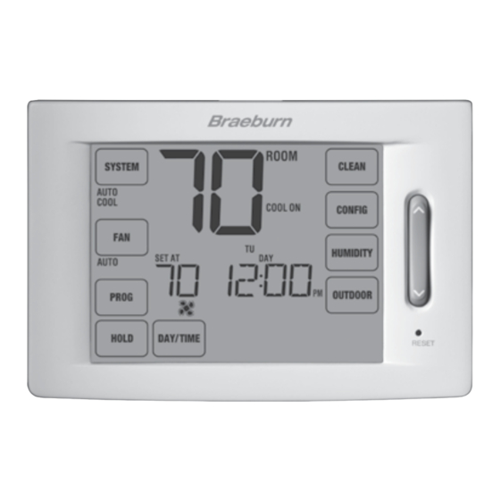
3 Quick Reference Instructions RESET RESET Thermostat Display Room Temperature ...... Displays the current room temperature Lock Mode Indicator ....Indicates if the thermostat is locked Set Temperature ...... D isplays the current set point temperature Humidity Indicator (6400 only) .. I ndicates when there is a call for humidity Fan Indicator ........ Indicates when the system fan is running Service Indicators ...... D isplays various service/maintenance information Time of Day ......... -
Page 9: Thermostat Touchpads Tm
“touch sensitive” segments used to adjust your thermostat. Depending on the equipment installed, all touch pads may not show. SYSTEM Selects AUTO (Heat/Cool), COOL, OFF HEAT or EMER (Emergency Heat) FAN Selects AUTO, ON, CIRC (Circulation) and PROG (Program) fan modes PROG Selects programming mode or press for 3 seconds to select SpeedSet mode HOLD Enters / Exits the HOLD mode (program bypass) DAY/TIME Sets the current time and day of the week BACK Moves back in setting and programming modes NEXT Moves forward in setting and programming modes RETURN Returns to normal mode from program or settings modes OUTDOOR Displays the outdoor temperature if a Braeburn outdoor sensor is installed ® HUMIDITY Displays or adjust the current humidity level (6400 only) CONFIG Enters the User and Installer settings modes CLEAN Enters a brief screen cleaning mode Installer Guide... -
Page 10: Installer Settings
Settings are menu driven. The portion of these settings that do not apply to your setup will be skipped. These settings are indicated below with comments. More detail on each setting follows this table. 1. Touch and hold down the SYSTEM and CONFIG TouchPads for 3 seconds. ™ 2. Release both buttons and the first installer setting will be displayed. 3. Change settings as required using the UP or DOWN portion of the SpeedBar ® 4. Touch NEXT or BACK to move to the next or previous setting, touch RETURN to exit. NOTE: Shaded areas below do not apply to the 6100. No. Installer Setting Factory Setting Comments Default Options Notes follow this table) (More information follows this table) - Page 11 Select a Heat Set Point Upper Limit of 90°-60° F (32°-10° C) 31 Cool Set Point Lower Limit 45LIM 45-80 LIM Select a Cool Set Point Lower Limit of 45°-80° F (7°-27° C) *When a Braeburn outdoor sensor is connected, the thermostat automatically recognizes it. ® NOTE: Additional options such as Service Monitors, Setting the lock code, audible tone, etc. are located in the User Settings – See User manual for information on setting these options.
- Page 12 NOTES - Installer Settings 1 Only available if Residential profile was selected in option 1. 2 Only available if a 2, 3 or 4 stage system type was selected in option 6. 3 Only available if a Conventional system was selected in option 6. 4 Only available if a 2, 3 or 4 stage Heat Pump system was selected in option 6. 5 Only available if a Heat Pump system was selected in option 6. 6 Only available if the 24 Volt AC common wire is connected to the C terminal. 7 Only available if a programmable profile was selected in option 2. 8 Only available if a Braeburn indoor remote sensor was connected. ® 9 Only available if humidification was enabled in option 23. 10 Only available if auto changeover was enabled in option 5. 11 Only available if a Braeburn outdoor sensor was connected. 12 Only available if Commercial profile was selected in option 1. Detailed Explanation of Installer Settings (also see NOTES above): Profile – Selects a residential (RES) or commercial (COMM) profile. If residential is selected, 4 programming events per day are available. If commercial is selected, 2 event, 7 day programming is available.
- Page 13 21 Indoor Remote Sensor Control [note 8] – If a Braeburn indoor remote sensor is connected during ® installation, the thermostat will automatically detect the sensor. When an indoor sensor is detected, you may select between thermostat only (I SENS), remote sensor only (E SENS) or combining the thermostat and the remote sensor (A SENS). NOTE: This option does not apply to a Braeburn outdoor sensor. When an outdoor sensor is connected the thermostat automatically recognizes it and no further configuration is necessary. 22 Lockout Security Level – Selects the level of keypad lockout when the thermostat is locked. Level 2 locks the entire thermostat (including the front reset button). Level 1 locks everything except the SpeedBar ®...
- Page 14 29 Outside Air Intake [note 12] – Selects economizer control options. Select between disabled (NONE), economizer mode (ECON) and time of day (TOD) mode. Time Step / Override Cooling Call External Air Output (A) Economizer Time of Disabled Mode Day Mode Occupied YES or NO Unoccupied Override YES or NO Time Step / Override Heating Call External Air Output (A) Economizer Time of Disabled...
-
Page 15: System Testing
5 System Testing Warning Read Before Testing • Do not short (or jumper) across terminals on the gas valve or at the heating or cooling system control board to test the thermostat installation. This could damage the thermostat and void the warranty. • Do not select the COOL mode of operation if the outside temperature is below 50º F (10º C). This could possibly damage the controlled cooling system and may cause personal injury. • This thermostat includes an automatic compressor protection feature to avoid potential damage to the compressor from short cycling. When testing the system, make sure to take this delay into account. NOTE: The compressor delay can be bypassed by pressing the reset button on the front of the thermostat. All user settings will be returned to factory default, however all Installer settings will remain as originally programmed in section 4. -
Page 16: Limited Warranty
Limited Warranty Braeburn Systems LLC warrants each new Braeburn thermostat against any defects that are due to faulty material or workmanship for a period of five years after the original date of purchase by a professional service technician. This warranty and our liability does not apply to batteries, nor does it include damage to merchandise or the thermostat resulting from accident, alteration, neglect, misuse, improper installation or any other failure to follow Braeburn installation and operating instructions. Braeburn Systems LLC agrees to repair or replace at its option any Braeburn thermostat under warranty provided it is returned postage prepaid to our warranty facility in a padded carton within the warranty period, with proof of the original date of purchase and a brief description of the malfunction. This limited warranty does not include the cost of removal or re-installation. This warranty gives you specific legal rights and you may also have other rights that vary from state to state or province to province. Answers to any questions regarding our limited warranty may be obtained by writing our corporate offices. - Page 17 Notes...
- Page 18 ® Braeburn Systems LLC 2215 Cornell Avenue • Montgomery, IL 60538 Technical Assistance: www.braeburnonline.com Call us toll-free: 866-268-5599 (U.S.) 630-844-1968 (Outside the U.S.) ©2011 Braeburn Systems LLC • All Rights Reserved • Patents Pending • Made in China • 6134-100-003...
Need help?
Do you have a question about the 6100 and is the answer not in the manual?
Questions and answers