Table of Contents
Advertisement
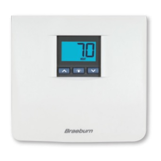
MODEL
3000
USER MANUAL
Compatible with low voltage single stage gas,
oil or electric heating or cooling systems,
including single stage heat pumps. This
thermostat can also be used on 250mv to
750mv millivolt heating only systems. Do not
use this thermostat on applications with
voltages above 30 Volts AC.
READ ALL INSTRUCTIONS BEFORE PROCEEDING
CONTENTS
1
SPECIFICATIONS
2
INSTALLATION
3
TESTING YOUR NEW THERMOSTAT
4
PROGRAMMING USER SETTINGS
5
ADDITIONAL OPERATION FEATURES
TROUBLESHOOTING
6
WIRING DIAGRAMS
7
© 2005 Braeburn Systems LLC • Patents Pending • All Rights Reserved.
Premier Series
Non-Programmable
Single Stage Heat/Cool
Digital Thermostat
Pub. No. 3000-100-006
WARNING!
Important Safety Information
• Always turn off power to the air conditioning or heating system prior to installing,
removing, cleaning or servicing thermostat.
• Read manual thoroughly prior to installing, programming or operating thermostat.
• This thermostat is designed for use with a 24 Volt-AC low voltage single stage gas,
oil or electric heating or cooling systems, including single stage heat pumps. This
thermostat can also be used on 250mv to 750mv millivolt heating only systems.
• Do not use this thermostat on applications with voltages above 30 Volts AC.
• This thermostat requires two (2) properly installed "AA" alkaline batteries to
provide power for the thermostat to properly control the system operation.
• The system must have 24 Volt AC power present for proper system operation and control.
• Wiring must conform to all building codes and ordinances as required by local and
national code authorities having jurisdiction.
• Do not short (or jumper) across terminals on the gas valve or at the heating or
cooling system control board to test the thermostat installation. This could
damage the thermostat and void the warranty.
• Do not select COOL mode of operation if the outside temperature is below 50˚ F
(10˚ C). This could damage the controlled cooling system and cause personal injury.
• This thermostat should only be used as described in this manual. Any other use is
not recommended and will void the warranty.
1
SPECIFICATIONS
• Electrical Rating: 24 Volt AC (18-30 Volt AC)
1 amp maximum load per terminal
2 amp total maximum load (all terminals)
• Control Range: 45˚ - 90˚ F (7˚ - 32˚ C)
• Accuracy: +/- 1˚ F (+/- .5˚ C)
• DC Power: 3.0 Volt DC (2 AA Alkaline batteries included)
• Compatibility with low voltage single stage gas, oil or electric heating or cooling
systems, including single stage heat pumps. This thermostat can also be used on
250mv to 750mv millivolt heating only systems.
• Terminations: Rc, Rh, G, W, Y, B, O
2
INSTALLATION
Replacing Existing Thermostat
2.1
1. Always turn off power to the air conditioning or heating system prior to removing
existing thermostat.
2. Remove the cover of your old thermostat and locate the wire terminals. Do not remove
wires from terminals yet.
3. Using small pieces of masking tape, label wires prior to removal from terminals. Use
the chart below to determine the new terminal designations for your new thermostat.
Old Terminal from
New Terminal for
Existing Thermostat
New Thermostat
V or Rc
Rc
M, 4, Rh, or R
Rh
G or F
G
H, W or 4
W
Y
Y
B
B
O
O
C
None-Cap the wire
Terminal Description
Cooling Transformer
Heating Transformer
Fan Control
Heating Control
Cooling Control
Reversing Valve (Heating)
Reversing Valve (Cooling)
24 Volt AC, Transformer Common
1
Advertisement
Table of Contents

Related Manuals for Braeburn 3000


Summary of Contents for Braeburn 3000
-
Page 1: Specifications
G or F Fan Control H, W or 4 Heating Control Cooling Control Reversing Valve (Heating) Reversing Valve (Cooling) None-Cap the wire 24 Volt AC, Transformer Common © 2005 Braeburn Systems LLC • Patents Pending • All Rights Reserved. Pub. No. 3000-100-006... -
Page 2: Installation
INSTALLATION INSTALLATION cont. cont. Replacing Existing Thermostat Installing Your New Thermostat cont. cont. 4. After labeling and removing all wires from terminals, unscrew the existing thermostat 19. Attach front body of thermostat to sub-base of thermostat, being careful to align sub-base from wall. -
Page 3: Programming User Settings
PROGRAMMING PROGRAMMING USER SETTINGS USER SETTINGS cont. Setting the Recirculating Fan Cycle (Also see section 5.3) Default Thermostat Settings Function Status After Reset 1. The display will show "SET OC XXX", where XXX Operation Mode Normal Operating Mode is the maximum interval of time (in minutes) that Room Temperature 70˚... - Page 4 ADDITIONAL ADDITIONAL OPERATION FEATURES OPERATION FEATURES cont. cont. (see section 4.4) Compressor Protection Feature Recirculating Fan Mode This thermostat includes an automatic compressor protection feature to avoid potential The Recirculating Fan Mode provides more even temperature distribution and improves damage to the cooling system from short cycling. This thermostat automatically provides a indoor air quality by circulating air through the furnace filtration system more often.
-
Page 5: Troubleshooting
TROUBLESHOOTING TROUBLESHOOTING cont. SYMPTOM POTENTIAL SOLUTION SYMPTOM POTENTIAL SOLUTION HI is shown in the The temperature sensed by the thermostat is higher than the Thermostat does not Check to see if OFF is shown in display. This indicates that the 90˚... -
Page 6: Wiring Diagrams
Technical Assistance: www.braeburnonline.com NOTE: For reversing valve active in heating, use B terminal instead of O terminal. Call us toll-free: 866-268-5599 (U.S. Only) 630-844-1968 (Outside the U.S.) © 2005 Braeburn Systems LLC • Patents Pending • All Rights Reserved. Pub. No. 3000-100-006...
Need help?
Do you have a question about the 3000 and is the answer not in the manual?
Questions and answers
This morning our Braeburn Thermostat 3000 (non programmable single stage heal/cool digital thermostat) was in LOCK position and we cannot get it off of lock.
To disable the lock feature on a Braeburn Thermostat 3000, press and hold either the up or down button together with the backlight key for 1 second. The LOCK icon will disappear from the display, and the keypad will be unlocked.
This answer is automatically generated
Just shows OFF WHEN SWITCH FROM HEAT OR COLD. Replaced batteries
The Braeburn 3000 thermostat shows OFF when switching from heat or cold if the system itself is turned off. This indicates that the thermostat is not actively controlling heating or cooling because the system is in the OFF mode.
This answer is automatically generated