Table of Contents
Advertisement
Installer Guide
Universal Programmable Smart Wi-Fi Thermostat
7205 Up to 3 Heat / 2 Cool Heat Pump
See Wi-Fi Setup Guide for Wi-Fi Setup Instructions
1 Specifications
Warning
For installation by experienced service technicians only.
Caution
• Possible electric shock or damage to equipment can occur.
• Disconnect power before beginning installation.
This thermostat requires 24 Volt AC Power or 2 properly installed "AA" Alkaline
batteries for proper operation. If connecting this thermostat to a Wi-Fi network,
a 24 VAC common (C wire) may be required (see page 3). Thermostat installation
and all components of the system shall conform to Class II Circuits per NEC code.
For use only as described in this manual. Any other use will void warranty.
1 Specifications
This thermostat is compatible with:
• Single stage heat / cool conventional and heat pump systems
• Conventional systems up to 2 stages of heating and 2 stages of cooling
• Heat pump systems up to 3 stages of heating and 2 stages of cooling
Electrical and control specifications:
• Electrical Rating: 24 Volt AC
• 1 amp maximum load per terminal
• AC Power: 18 – 30 Volts AC
• DC Power: 3.0 Volt DC (2 "AA" Alkaline Batteries Included)
• Control Range: 45° – 90° F (7° – 32° C)
• Temperature Accuracy: +/- 1° F (+/- .5° C)
Terminations
Rh, Rc, C, W1/E/W3, W2, O/B, G, Y2, Y1, K
Up to 2 Heat / 2 Cool Conventional
Model number is located on back of thermostat.
2 Installation and Wiring
4 Installer Settings
®
3 Quick Reference
5 System Testing
®
7205-100-03
Advertisement
Table of Contents

Related Manuals for Braeburn BlueLink 7205


Summary of Contents for Braeburn BlueLink 7205
- Page 1 ® Installer Guide ® Universal Programmable Smart Wi-Fi Thermostat 7205 Up to 3 Heat / 2 Cool Heat Pump Up to 2 Heat / 2 Cool Conventional Model number is located on back of thermostat. See Wi-Fi Setup Guide for Wi-Fi Setup Instructions 1 Specifications 2 Installation and Wiring 3 Quick Reference...
-
Page 2: Installation And Wiring
Avoid installation in locations where the thermostat can be affected by drafts, dead air spots, hot or cold air ducts, sunlight, appliances, concealed pipes, chimneys and outside walls. Install your new Braeburn thermostat in 4 basic steps: 1 Install the Sub-Base... - Page 3 Provide Power 24VAC Power Terminal (C) Batteries Installed as Shown • For 24 Volt AC power, you must connect the common side of the transformer to the C terminal on the thermostat sub-base. In dual transformer installations, the transformer common must come from the cooling transformer.
-
Page 4: Connecting Your Wires
Connecting Your Wires Wiring Terminations Terminal Function Description Input 24 Volt AC Cooling Transformer (Dual Transformer Systems Only) Input Power Connection (24 Volt AC Heating Transformer) Output Fan Control W1 / E / W3 Output (W1) 1st Stage Conventional Heat, (E) Emergency Heat, (W3) 3rd Stage Auxiliary Heat Output... -
Page 5: Conventional Systems
Conventional Systems Typical Wiring Configurations NOTE: The “System Type” option will be configured in the Installer Settings section. 2 HEAT / 2 COOL Single or Dual transformer Heat Only* Set System Type to CONV 22 Set System Type to CONV 11 Rh 24 Volt AC Power (heating transformer) [note 2] Rh Power Connection Rc 24 Volt AC Power (cooling transformer) [note 2]... -
Page 6: Heat Pump Systems
Heat Pump Systems Typical Wiring Configurations NOTE: The “System Type” option will be configured in the Installer Settings section. 1 HEAT / 1 COOL - No Auxiliary Heat 3 HEAT / 2 COOL – Including Auxiliary Heat Set System Type to HP 11 Set System Type to HP 32 Rh 24 Volt AC Power 24 Volt AC Power... -
Page 7: Attach Thermostat To Sub-Base
Attach Thermostat to Sub-Base INSTRUCTIONS FAN AUTO DAY/TIME 1) Line up the thermostat body with the sub-base. 3) Insert Quick Reference Card into slot 2) Carefully push the thermostat body against the on top of thermostat. sub-base until it snaps in place. NOTE: This thermostat ships configured as a 1H/1C conventional thermostat. -
Page 8: Quick Reference
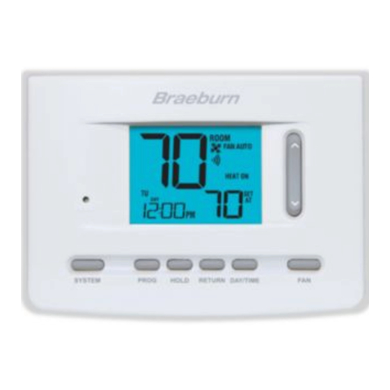
3 Quick Reference FAN AUTO Thermostat Display Room Temperature ...... Displays the current room temperature Hold Mode Indicator ....Indicates if the thermostat is in HOLD mode Fan Indicator ........ Indicates when the system fan is running Wi-Fi Indicator ......Indicates when connected to Wi-Fi (flashes when connection has been lost) System Status Indicator ..... - Page 9 INSTRUCTIONS FAN AUTO DAY/TIME Thermostat Quick Reference Instructions ..Stored in slot located at top of thermostat SpeedBar ........Increases or decreases settings (time, temperature, etc.) ® FAN Button ........Selects the system fan mode DAY/TIME Button ......Sets the current time and day of the week RETURN Button ......
-
Page 10: Installer Settings
4 Installer Settings The Installer Settings must be properly configured in order for this thermostat to operate correctly. The Installer Settings are menu driven. The portion of these settings that do not apply to your setup will be skipped. These settings are indicated below with comments. - Page 11 No. Installer Setting Factory Setting Comments Default Options Notes follow this table) (More information follows this table) BAND 3 BAND 2, 3, Auto Changeover Select a Dead Band of 2°, 3°, 4° or 5° F 4 or 5 Dead Band [note 6] (1°, 2°...
- Page 12 NOTES - Installer Settings 1 Only available if a 2 or 3 stage system type was selected in option 4. 2 Only available if a Conventional system was selected in option 4. 3 Only available if a 2 or 3 stage Heat Pump system was selected in option 4. 4 Only available if a Heat Pump system was selected in option 4.
- Page 13 17 Adaptive Recovery Mode (early recovery) [note 5] – Enables or disables the ARM (adaptive recovery mode) feature. During ARM, room temperature is recovered by turning on the heating or cooling before the end of the set back period. The set point temperature is changed to that of the upcoming program temperature. 18 User Lockout Security Level –...
-
Page 14: System Testing
5 System Testing Warning Read Before Testing • Do not short (or jumper) across terminals on the gas valve or at the heating or cooling system control board to test the thermostat installation. This could damage the thermostat and void the warranty. •... -
Page 15: Limited Warranty
Limitations apply. For limitations, terms and conditions, you may obtain a full copy of this warranty: LIMITED WARRANT Y · Visit us online: www.braeburnonline.com/warranty · Phone us: 866.268.5599 · Write us: Braeburn Systems LLC 2215 Cornell Avenue Montgomery, IL 60538 Installer Guide... - Page 16 For online access visit: www.bluelinksmartconnect.com ® Braeburn Systems LLC 2215 Cornell Avenue • Montgomery, IL 60538 Technical Assistance: www.braeburnonline.com Call us toll-free: 866-268-5599 (U.S.) 630-844-1968 (Outside the U.S.) 7205-100-03 ©2017 Braeburn Systems LLC • All Rights Reserved • Made in China.
Need help?
Do you have a question about the BlueLink 7205 and is the answer not in the manual?
Questions and answers