Table of Contents
Advertisement
Quick Links
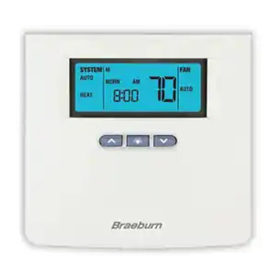
Premier Series
Universal Auto Changeover
Up to 3 Heat / 2 Cool Heat Pump
or 2 Heat / 2 Cool Conventional Thermostat
Installer Guide
Before Installing, Programming or Operating,
PLEASE READ ALL INSTRUCTIONS
Specifications
1
Installation
2
Quick Reference
3
Programming Installer Settings
4
SEE USER MANUAL FOR TROUBLESHOOTING
WARNING
Important Safety Information
• Always turn off power to the air conditioning or heating system prior to
Installing, removing, cleaning or servicing thermostat.
• This thermostat is a dual power thermostat and either requires 24 Volt
AC Power or two (2) properly installed "AA" Alkaline batteries for normal
operation and control of the heating or cooling system.
• Properly installed batteries will allow the thermostat to retain clock settings in
the event of loss of AC Power due to power outage or rolling blackouts when
used as a hardwired thermostat.
• This thermostat should only be used as described in this manual. Any other
use is not recommended and will void the warranty.
1
Specifications
• Electrical Rating: 24 Volt AC (18-30 Volt AC)
1 amp maximum load per terminal
5 amp maximum load (all terminals)
• Control Range: 45º - 90º F (7º C - 32º C)
• Accuracy: +/- 1º F (+/- .5º C)
• AC Power: 18-30 Volt AC
• DC Power: 3.0 Volt DC (2 "AA" Alkaline batteries included)
5300
Testing Thermostat
5
Wiring Diagrams
6
1
Specifications
• Compatibility: Compatible with low voltage single stage or multi-stage
Heat / Cool systems, including heat pumps with up to three stages of heating
and two stages of cooling, or conventional systems with up to two stages of
heating and two stages of cooling. This thermostat can also be used on 250 to
750 millivolt heating only systems.
• Terminations: A, G, Rc, Rh, W2, B, O, Y1, Y2, W1/E/W3, C, L, S1, S2
2
Installation
Replacing Existing Thermostat
Most existing thermostats have three parts:
• The cover, which may snap or hinge over the existing thermostat.
• The electronics or body, which controls the existing system.
• The sub-base, where the wires attach through the wall to the existing system.
1. Always turn off power to the air conditioning and heating system prior to
removing existing thermostat.
2. Carefully remove the cover and electronics body from the old thermostat
sub-base. Depending on the brand, these parts may pull off or need to be
unscrewed. The old sub-base should remain wired and on the wall until
steps 4 and 5.
3. Label every old wire with the letter of the connection to which the wire is
attached. Example letters are R, M, Y, etc. Depending on the brand of the
old thermostat, your letters may be different. (continued on page 2)
Old Terminal from
New Terminal for
Existing Thermostat
New Thermostat
(Model 5300)
A
A
G or F
G
Rc
Rc
R, V-VR or VR-R
Rh
W1, W2 or W-U
W2
B
B
O or R
O
Y, Y1 or M
Y1
Y2
Y2
W1/E/W3
W1/E/W3
C, X or B
C
L or X
L
S1
S1
S2
S2
cont.
Terminal Description
External Air output
Fan Control
24 Volt AC (Cooling for
Dual Transformer Systems)
24 Volt AC
Stage 2 Heating
Reversing Valve (Heating)
Reversing Valve (Cooling)
Stage 1 Compressor
Stage 2 Compressor
1st Stage Heating for
Conventional Systems or
Emergency Heating for 3
Stage Heat Pumps
24 Volt AC, Transformer
Common
System Malfunction Indicator
Optional Remote Sensor
Optional Remote Sensor
1
Advertisement
Table of Contents

Related Manuals for Braeburn 5300


Summary of Contents for Braeburn 5300
-
Page 1: Quick Reference
Old Terminal from New Terminal for Existing Thermostat New Thermostat Terminal Description WARNING (Model 5300) External Air output Important Safety Information G or F Fan Control 24 Volt AC (Cooling for • Always turn off power to the air conditioning or heating system prior to Dual Transformer Systems) Installing, removing, cleaning or servicing thermostat. -
Page 2: Installation
It may be helpful to use the chart by circling (with a pencil or pen) the letter of each wire removed from the old thermostat. Model 5300 shown with cover open NOTE: This thermostat is designed for use on low voltage 24 volt AC single stage or multi-stage systems, including heat pumps with up to three stages of heating and two stages of cooling. - Page 3 Programming Installer Settings Programming Installer Settings cont. Status After CLEAR–Factory Default Settings Status After CLEAR–Factory Default Settings (continued) At initial power up or after Installer CLEAR is pressed, the thermostat is Function Status After CLEAR reset to factory defaults. Installer CLEAR is located on the circuit board. Auxiliary Balance Point 0 deg –...
- Page 4 Programming Installer Settings Programming Installer Settings cont. cont. Setting Thermostat Installer Options Setting Thermostat Installer Options (continued) The Installer Options section allows the system and programming parameters to be set up at installation. The Installer Options mode is menu driven. As the different options are programmed you may eliminate specific options.
- Page 5 Programming Installer Settings Programming Installer Settings cont. cont. Setting Thermostat Installer Options (continued) 12. This thermostat includes an automatic compressor protection feature to avoid potential damage to the cooling system from short cycling. This thermostat automatically provides an adjustable delay after turning off the cooling system output to protect the compressor.
- Page 6 Programming Installer Settings Programming Installer Settings cont. cont. 16. If a Braeburn 20. Only available with multi-stage heat pump and outdoor sensor connected. indoor or outdoor remote sensor is connected during installation, ® the thermostat will automatically detect the type of sensor. When an indoor Locks out the use of the auxiliary heat stage for outside air temperatures over sensor is detected, you may select between internal (sensI), external (sensE), installer setting.
-
Page 7: Testing The Thermostat
Testing the Thermostat WARNING! Read BEFORE Testing • Do not short (or jumper) across terminals on the gas valve or at the heating or cooling system control board to test the thermostat installation. This could damage the thermostat and void the warranty. •... -
Page 8: Wiring Diagrams
Wiring Diagrams Retain Factory Installed Jumper Conventional Systems (Single Transformer) W1/ E/W3 C 1st Stage 1st Stage Compressor Heat Control Control Fan Control Remote Outside 2nd Stage 2nd Stage Sensor Air Control Heat Control Compressor (NOTE 3) (NOTE 2) Control (NOTE 2) Neutral 24 VAC... - Page 9 Wiring Diagrams cont. One and Two Stage Heat Pump Systems Factory Installed Jumper (See NOTE 5) W1/ E/W3 C 2nd Stage Reversing Valve 2nd Stage System Heat Control Malfunction (Active in Compressor Outside (NOTE 2) Cooling - See Control Indicator Air Control NOTE 3) (NOTE 2)
-
Page 10: Warranty
2215 Cornell Avenue • Montgomery, IL 60538 Technical Assistance: www.braeburnonline.com Call us toll-free: 866-268-5599 (U.S.) 630-844-1968 (Outside the U.S.) ©2009 Braeburn Systems LLC • All Rights Reserved. U.S. Patents D525,154; D531,528; 7,156,317; 7,438,469 • Made in China • No. 5300-100-008...
Need help?
Do you have a question about the 5300 and is the answer not in the manual?
Questions and answers