Table of Contents
Advertisement
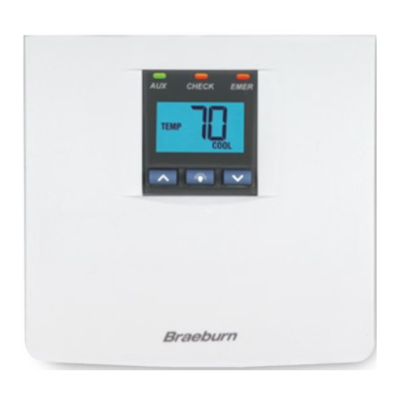
MODEL
3200
USER MANUAL
Compatible with low voltage multi-stage heat
pump systems with up to two stages of heating
and two stages of cooling. Not for use on
single-stage heating or cooling systems.
READ ALL INSTRUCTIONS BEFORE PROCEEDING
CONTENTS
1
SPECIFICATIONS
2
INSTALLATION
3
TESTING YOUR NEW THERMOSTAT
4
PROGRAMMING USER SETTINGS
5
ADDITIONAL OPERATION FEATURES
TROUBLESHOOTING
6
WIRING DIAGRAMS
7
© 2005 Braeburn Systems LLC • Patents Pending • All Rights Reserved.
Premier Series
Non-Programmable
2 Heat / 2 Cool Heat Pump
Digital Thermostat
Pub. No. 3200-100-006
WARNING!
Important Safety Information
• Always turn off power to the air conditioning or heating system prior to installing,
removing, cleaning or servicing thermostat.
• Read manual thoroughly prior to installing, programming or operating thermostat.
• This thermostat is designed for use with a 24 Volt-AC low voltage multi-stage
heat pump system.
• Do not use this thermostat on single stage systems or other systems with
voltages higher than 30 Volt-AC.
• This thermostat requires 24 Volt AC power for normal operation and control of
the heating or cooling system.
• Wiring must conform to all building codes and ordinances as required by local
and national code authorities having jurisdiction.
• Do not short (or jumper) across terminals on the gas valve or at the heating or
cooling system control board to test the thermostat installation. This could
damage the thermostat and void the warranty.
• Do not select COOL mode of operation if the outside temperature is below 50˚ F
(10˚ C). This could damage the controlled cooling system and cause personal injury.
• This thermostat should only be used as described in this manual. Any other
use is not recommended and will void the warranty.
1
SPECIFICATIONS
• Electrical Rating: 24 Volt AC (18-30 Volt AC)
2 amp maximum load per terminal
4 amp total maximum load (all terminals)
• Control Range: 45˚ - 90˚ F (7˚ - 32˚ C)
• Accuracy: +/- 1˚ F (+/- .5˚ C)
• AC Power: 18-30 Volt AC
• Compatibility: Multi-stage heat pump systems with up to two stages of heating
and two stages of cooling.
• Terminations: R, Y1, Y2, W2, E, G, O, B, L, C
2
INSTALLATION
2.1
Replacing Existing Thermostat
1. Always turn off power to the air conditioning or heating system prior to removing
existing thermostat.
2. Remove the cover of your old thermostat and locate the wire terminals. Do not
remove wires from terminals yet.
3. Using small pieces of masking tape label wires prior to removal from terminals. Use
the chart below to determine the new terminal designations for your new thermostat.
Old Terminal from
New Terminal for
Existing Thermostat
New Thermostat
R, V-VR or VR-R
R
Y, Y1 or M
Y1
Y2
Y2
W1, W2 or W-U
W2
E
E
G or F
G
O or R
O
B
B
L or X
L
C, X or B
C
4. After labeling and removing all wires from terminals, unscrew the existing thermostat
sub-base from wall. Make sure to secure wires to prevent them from slipping back
into the hole in the wall.
Terminal Description
24 Volt AC
Stage 1 Cooling or Heating
Stage 2 Cooling
Stage 2 Heating
Emergency Heating
Fan Control
Reversing Valve (Cooling)
Reversing Valve (Heating)
System Status LED
24 Volt AC, Transformer Common
1
Advertisement
Table of Contents

Related Manuals for Braeburn 3200


Summary of Contents for Braeburn 3200
-
Page 1: Specifications
4. After labeling and removing all wires from terminals, unscrew the existing thermostat sub-base from wall. Make sure to secure wires to prevent them from slipping back into the hole in the wall. © 2005 Braeburn Systems LLC • Patents Pending • All Rights Reserved. Pub. No. 3200-100-006... -
Page 2: Installation
TESTING YOUR INSTALLATION NEW THERMOSTAT cont. Replacing Existing Thermostat cont. WARNING! Read BEFORE Testing NOTE: • Do not short (or jumper) across terminals on the gas valve or at the heating or cooling This thermostat is for use on low voltage 24 Volt AC multi-stage heat pump system control board to test the thermostat installation. -
Page 3: Setting Temperature Differentials
PROGRAMMING PROGRAMMING USER SETTINGS USER SETTINGS cont. cont. Setting the Recirculating Fan Cycle Setting Temperature Differentials (Also see section 5.3) The default is 120 minutes. The default settings for the first and second stage differentials and residual cooling fan delay settings are compatible with most systems and applications. -
Page 4: Recirculating Fan Mode
TROUBLESHOOTING Auxiliary Heat Fossil Fuel Switch The Model 3200 is equipped with an auxiliary heat option switch which is set at installation SYMPTOM POTENTIAL SOLUTION for either an electric or fossil fuel (gas, oil or propane) auxiliary heat source. For heat pump units with an electric auxiliary stage, both the first and second stages of heating will run... - Page 5 TROUBLESHOOTING TROUBLESHOOTING cont. cont. SYMPTOM POTENTIAL SOLUTION SYMPTOM POTENTIAL SOLUTION Thermostat turns on Increase or decrease second (auxiliary) stage temperature Thermostat will not This is above the normal thermostat temperature setting range differential setting as appropriate to provide the desired of 45˚...
-
Page 6: Wiring Diagram
Montgomery, IL 60538 Braeburn Systems LLC 2215 Cornell Avenue • Montgomery, IL 60538 Technical Assistance: www.braeburnonline.com Call us toll-free: 866-268-5599 (U.S. Only) 630-844-1968 (Outside the U.S.) © 2005 Braeburn Systems LLC • Patents Pending • All Rights Reserved. Pub. No. 3200-100-006...
Need help?
Do you have a question about the 3200 and is the answer not in the manual?
Questions and answers
In cool mode the AUX light flashes and I don’t feel cold air. I ran it for a few minutes and the room temperature climed from 71 to 77. Turned it off.
If the AUX light flashes on a Braeburn 3200 thermostat and there is no cold air, it likely means the system is in Emergency Heat (EM HEAT) mode. This mode is used when the primary heating system is not working properly. The lack of cold air suggests the system is not in cooling mode. Check the system switch setting and verify correct wiring to ensure heating and cooling stages are connected to the right terminals.
This answer is automatically generated