Panasonic WJ-ND400 Operating Instructions Manual
Network disk recorder
Hide thumbs
Also See for WJ-ND400:
- Operating instructions manual (69 pages) ,
- Installation manual (60 pages) ,
- Reference material (22 pages)
Table of Contents
Advertisement
Quick Links
Advertisement
Chapters
Table of Contents
Troubleshooting

Related Manuals for Panasonic WJ-ND400


Summary of Contents for Panasonic WJ-ND400
-
Page 1: Operating Instructions
Network Disk Recorder www.voicesonic.com Phone: 877.289.2829 Operating Instructions WJ-ND400 Model No. Panasonic I-Pro Network Cameras Before attempting to connect or operate this product, please read these instructions carefully and save this manual for future use. -
Page 2: Table Of Contents
Contents Preface Preface Preface................................5 About these Operating Instructions........................5 System Requirements for a PC ........................6 Trademarks and Registered Trademarks ......................6 Restrictions when operating MPEG-4 images ..............7 About operating windows ......................8 Display and close the operating window......................8 Names and functions of components...................... - Page 3 Contents Operations during an event..........................34 Canceling alarm action ..........................34 Suspend alarm action ..........................34 Cancel the Error Status ..........................35 Preventing illegal operations....................36 Lock ................................36 Cancel................................36 Checking logs ........................37 Error log ................................37 Access log............................... 37 Event log .................................
- Page 4 Contents Troubleshooting........................60 Problems................................. 60 Message display ............................. 64 Glossary..........................65 Words used in the manual ..........................65 Index............................68...
-
Page 5: Preface
Preface The Network Disk Recorder (WJ-ND400) is for recording images and audio from network surveillance cameras to a hard disk (hereafter HDD). It is possible to connect up to 64 cameras over a network. Also, it is possible to access and operate the recorder via a network from the web browser on a computer (hereafter PC). A maximum of 16 PCs can be connected (via a network). -
Page 6: System Requirements For A Pc
System Requirements for a PC It is recommended to operate this unit using a PC that meets the following system requirements. ® ® • OS : Microsoft Windows Vista Business (32-bit) ® ® : Microsoft Windows XP Professional SP2 ® ®... -
Page 7: Restrictions When Operating Mpeg-4 Images
Restrictions when operating MPEG-4 images There are following restrictions when "MPEG-4" is selected for the 4. When recording images image compression method on the setup menu. ("NW camera" (1) Time and date displayed on the recording event list (actual under "Camera") start time of recordings) may not exactly indicate the actual time of recording trigger (event occurrence time, start time of When displaying live images... -
Page 8: About Operating Windows
About operating windows Display and close the operating window Operate the recorder from a web browser on a PC. Start the PC. Enter a "User name" and "Password" that is registered with the recorder, and click the [Login] button. The top page is displayed. Launch the web browser. - Page 9 Follow the on-screen instructions. • If WJ-ND200/WJ-ND300 ActiveX is already installed, delete WebVideo ActiveX using Add or Remove Programs and then install WJ-ND400 ActiveX. • When the install wizard is displayed again even after completing the installation of the ActiveX, restart the PC.
-
Page 10: Names And Functions Of Components
About operating windows Names and functions of components Top page (1) [Control] button (page 11) (8) [HDD] tab (page 15) Performs operations such as searching for recorded images. Controls recorded images, such as playing images or You can also perform the functions of the camera picture downloading to save to a PC. -
Page 11: [Control] Button
About operating windows (4) [Search] box [Control] button [Search] button The following operation panel appears when you click the [Control] Searches for recorded images. The search results are shown button. on the rec event list window (page 24, page 25). [Area select] button Selects disk to play or search (page 26). -
Page 12: [Cam. Select] Button
(4) [Cam. select] box Displays the group titles of the cameras connected to the recorder when clicking [WJ-ND400]. Refer to the Setup Instructions (PDF file) for information about group settings. Displays the cameras the belong to that group when clicking a group title. -
Page 13: [Setup] Button
About operating windows (7) [Server] button [Setup] button Displays a menu for setting the server of recorder. The following operation panel appears when you click the [Setup] (8) [Network] button button. Displays a menu for setting the network of recorder. Refer to the Setup Instructions (PDF file) for more information. -
Page 14: Status Display Area
About operating windows Status display area (1) Displays the status of live and playback (2) [REC] indicator images. Displays the recording status. : Live images are being displayed. : Recording is being performed. : Recorded images are being played back. : Recording is not being performed. -
Page 15: Playback Point Operation Area
About operating windows Playback point operation area (1) Displays the time and date for the download (2) [Go to date] button start point/ending point. (page 42) Used to playback images from a specified time and date. (page 22). [Start] : Set the time and date to start the image to be downloaded. - Page 16 About operating windows Note: • The operations are as follows when the image for playback is an MPEG-4 image. Date/Time Search : Playback may start a few seconds before or after the specified time. Reverse Playback : Not all recorded images are displayed.
-
Page 17: [Cam] Tab
About operating windows [CAM] tab The camera can be controlled (pan/tilt, zoom, focus, brightness, preset, auto mode) when the live image is from a camera that can pan and tilt. Some camera operations cannot be done depending on the type of camera connected. (1) [Zoom] box Click [-] or [+] to adjust the zoom. -
Page 18: Recording Images And Audio
Recording images and audio Recording and playing images Recording mode and priority Manual recording of images and audio The recorder has 5 recording modes. The access priority of the recording modes is shown below. Images are recorded in the You can set the recorder for manual recording of images and audio. highest priority mode when two or more recordings with different Check with your system administrator about the manual recording recording modes started simultaneously, only recording with the... -
Page 19: Playback
Playback Playback recorded images Play back recorded images. There are three ways to play recorded images, specify a time and date, specify search conditions, or select a disk. Click the [HDD] tab. Click the [PLAY] button. Plays recorded images. "Playback operation [Step 1]" is displayed in the status display area. -
Page 20: Operations During Playback
Playback Operations during playback Function Button Operation Playback/reverse playback • Plays recorded images. • Plays recorded images in reverse. Note: • Clicking the [Play] or [Reverse play] button while recording at a low rate may not play the images being recorded either forward or reverse. Stop •... - Page 21 Playback Function Button Operation Playback on a multiscreen • Images being played back are displayed on a split screen (4-screen). • Displays multiple images from up to 4 cameras at the same time. Each time the button is clicked, the 4 screens change. Refer to the Setup Instructions (PDF file) for information about camera group settings.
-
Page 22: Playback From A Designated Time And Date
Playback On the [HDD] tab, click the [STOP] button. Playback from a designated time "Playing [Step 1]" disappears from the status display area and playback is stopped. and date • The live image from the camera is displayed in the Image display. -
Page 23: Filter Conditions
Playback Filter conditions Filter Search Conditions Time and Select the starting and ending time and date to search for images recorded during that period. date Event Search only for images of the selected recording mode. Select from the following recording modes. •... -
Page 24: Search For And Playback Recorded Events
Playback Click the [OK] button. Search for and playback recorded events • [FILTERING] is displayed on the status display area and the filtered results are displayed. Click the [Control] button. • This displays the search results on the rec event list window. -
Page 25: Search For And Playback Images With Motion At A Specific Time And Date (Vmd Search)
Playback Click the [V] button and set the date range and the basic Search for and playback images with channel for the VMD search. motion at a specific time and date (VMD Set the area for the motion search. search) Specify the area by dragging the mouse on the area of the image. -
Page 26: Select An Area To Play Back
Playback • "Playing [Step 1]" disappears from the status display area and a live image from the camera is displayed in the Note: Image display. • When doing a VMD search in the multiple image screen, the • If you press the [PLAY] button after stopping playback, upper-left image is searched. -
Page 27: Live Images
Note: • About Selecting a Camera Click [WJ-ND400] to display the group titles of the cameras set on the recorder. Clicking a group title displays the cameras that belong to that group. Clicking a camera's title displays that camera's image. -
Page 28: Useful Functions While Images Are Displayed
Live images Useful functions while images are displayed Function Name Button Operation Electronic zoom • Enlarges live images. Clicking the button in the [El-zoom] box while one screen is being displayed enlarges the image. [x1] button: Digitally zooms image by 1x. [x2] button: Digitally zooms image by 2x. -
Page 29: Camera Control
Live images Zoom, focus, brightness operations Camera control Adjust the zoom, focus, and brightness of the image. The following camera operations are available when live images Zoom : Adjust the size of the image. The degree of from a camera with the pan and tilt function are displayed on a single zoom depends on the type of camera. - Page 30 Live images Registration of a camera direction on the preset Auto mode function (Auto pan etc.) position. Operates the auto functions set for the camera. The current camera direction can be registered on the specified preset position. Registered preset positions can be used with a Click the [CAM] tab.
-
Page 31: 4-Screen (Multiscreen)
Live images 4-screen (Multiscreen) Display switching (Sequence) Images from cameras will be displayed on a 4-screen. Automatically switches the camera image. Refer to page 28 for information about this handy function for use while images are displayed. Click the [Cam. select] button. Click the [Cam. - Page 32 Live images Note: • If you perform VMD search (page 25), 1-screen (page 27), or 4- screen (page 25) during sequence operations, the sequence operation will stop. • When an image in the sequence cannot be displayed, the image for the next step is displayed. (MPEG-4 image is also unavailable to display.
-
Page 33: Event
• A PC is notified of an alarm according to Panasonic alarm recorder. protocol settings When an event or error occurs, a PC is automatically notified •... -
Page 34: Operations During An Event
Event Operations during an event When an event occurs and is recognized by the recorder, alarm action starts according to the settings. Refer to page 33 for information about alarm action. Note: • When an event occurred and the corresponding camera's compression method is "MPEG-4", event recording may start from a point several seconds after the event occurrence and the recording duration may be shortened for several seconds. -
Page 35: Cancel The Error Status
Event Cancel the Error Status When an error occurred, the unit will be in the error status. To release the unit from the error status, do the following. When an error occurred, the [ERR] button will be displayed in the status display area. Click the [ERR] button. -
Page 36: Preventing Illegal Operations
Preventing illegal operations You can lock the buttons on the front panel of the recorder to prevent them from being operated. Lock Cancel Press the arrow buttons (up or down) on the front panel. Press the arrow buttons (up or down) on the front panel. Continue to press it until [Keylock Mode] is displayed. -
Page 37: Checking Logs
Checking logs You can check logs of malfunctions, access, events (time/date, description), and network malfunctions. Error log Access log You can view a listing of the errors that have occurred on the Displays the log in/log out time and date, the user name and IP recorder. -
Page 38: Event Log
Checking logs Event log Network log You can view the Event log (when events occurred and a You can view the Network log (when they occurred and a description) in a list. For information about events, refer to page 33. description) in a list. -
Page 39: Copying Recorded Images
Copying recorded images Images recorded to a disk can be selected and copied to an area on a HDD. We recommend backing up important data in case of HDD malfunction or unexpected accident. Copying Important: You can copy images recorded in the Normal recording area/Event •... -
Page 40: Playing Back Copied Images
Copying recorded images Playing back copied images You can playback copied images. Click the [Control] button. Click the [Area select] button in the [Search] box. This will display the [Area select] screen. Select the [Copy area] check box. Click the [OK] button. Logs (when copied and a description) of copied images are shown in a list in the rec event list. -
Page 41: Deleting Images
Deleting images Manual deletion You can manually delete images and audio recorded on the Normal recording area, Event recording area and Copy area of the recorder's HDD. By setting a time and date, the images recorded the day before the set time and date will be subject to deletion. Important: •... -
Page 42: Downloading Images
Downloading images • The download time is longer if audio or alteration Downloading images for detection data is attached. playback You can download images to the PC by setting the start and end time and date for download of images being played back. Downloaded images are saved as image data files (file name.n3r) and audio data file (file name.n3a). -
Page 43: Downloaded Image Operations
Downloading images Installing the viewer software Downloaded image operations When you download an image for playback, image data (file You must uninstall any previous versions of the viewer software name.n3r), and audio data (file name.n3a) are downloaded. Using before installing the latest version. the viewer software available for download from the recorder, you can playback, save, and print downloaded data. -
Page 44: Uninstalling The Viewer Software
Downloading images Select [Anyone who uses this computer (all users)] and Uninstalling the viewer software then click the [Next >] button. The wizard is ready to install. In Windows XP Select [Add or Remove Programs] from the Control Panel. Select [ND_Viewer] from the list of installed programs, and then click the [Remove] button. -
Page 45: Saving Images
Downloading images Select the downloaded image data (file name.n3r). Saving images • You can select multiple files while pressing either the [Ctrl] or [Shift] keys. A maximum of 32 files can be Displayed images are saved to the PC as jpeg files. selected. -
Page 46: Printing Images
Downloading images Click the [Open File (OPEN)] button. Printing images The [Open] window opens. You can pause playback and print images displayed on screen with the viewer software. Play back an image with the viewer software. Select the downloaded image data (file name.n3r). Click the [Open] button. -
Page 47: Transmitting Data
Transmitting data Transmitting to the FTP server Send mail You can transmit camera images to the FTP server. You can either Alarm mail (notification of the time and date of an event) is sent to use image transmission by periodic timer [Image transmission by registered e-mail addresses when an event occurs. -
Page 48: Checking System/Disk Information
Checking system/disk information For checking information about the HDDs and the recorder system. System information Disk information Displays software and hardware versions, MAC address, serial You can view the capacities and the remaining space available of number, internal temperature, and Extension unit software version the recorder's HDDs and Extension units (Ext.1 to 5). -
Page 49: About Mail Notification
About mail notification Attachments Alarm mail notification The main unit's address appears in the alarm mail as shown below. Contents of the alarm mail ND400 (192.168.0.250), alarm was occurred. Alarm date: xx-xxx-xxxx xx:xx:xx GMT xx:xx (Example: 01-JAN- 2008 GMT+0:00) Cause of alarm: Displays an event type and a camera channel or an alarm number (Example: COMMAND ALARM 5CH) File name of alarm image: The file name of the image attached to an e-mail. - Page 50 About mail notification Item Description RAID5 recovery failure Recorder: MAIN RAID5 RECOVERY FAILURE Extension unit: EXTx RAID5 RECOVERY FAILURE x is unit number. RAID6 recovery failure Recorder: MAIN RAID6 RECOVERY FAILURE Extension unit: EXTx RAID6 RECOVERY FAILURE x is unit number. Fan trouble Recorder: MAIN FANy ERROR Extension unit: EXTx FANy ERROR...
- Page 51 About mail notification Item Description RAID6 mode format failure Recorder: MAIN RAID6 FORMAT ERROR Extension unit: EXTx RAID6 FORMAT ERROR x is unit number. HDD remove error Recorder: MAIN-y SWAP WARNING Extension unit: EXTx-y SWAP WARNING x is unit number, y is disk number. Alteration detected :ALTERED **CH ** is camera channel.
-
Page 52: Error Log
− − − Alteration Detection ALTERED **CH No response from a address PANASONIC_ALM_RES_E Network error − − of Panasonic alarm protocol output Failed to resolve a address PANASONIC_ALM_ADD_ Network error − − of Panasonic alarm protocol output from DNS Other errors for a address of... - Page 53 Error log Output from Description of error Error log Network log connector Single mode format failure Recorder: MAIN-d Recorder: MAIN-d ERR HDD error output SINGLE HDD FORMAT FORMAT FAIL ERROR − Extension EXTu-d Extension EXTu-d ERR unit: SINGLE unit: HDD FORMAT FORMAT FAIL ERROR...
- Page 54 Error log Output from Description of error Error log Network log connector HDD SKIP warning Recorder: MAIN-d HDD SKIP − − − Extension EXTu-d HDD unit: SKIP Remove HDD auto links Recorder: MAIN-d Recorder: MAIN-d ERR HDD error output (per HDD) LOGICALLY HDD REMOVE REMOVED...
- Page 55 Error log Output from Description of error Error log Network log connector Copy area available COPY-HDD FULL AREA ERR COPY-HDD FULL Available disk − capacity warning space warning (FULL) output − − − Copy error NO DATA COPY Network link error NETWORK LINK NW ERR NW LINK ERROR Network error...
- Page 56 Error log Output from Description of error Error log Network log connector FTP log-in failure <FTP>LOGIN_FAULT Network error − − output FTP log-out failure <FTP>LOGOUT_FAULT Network error − − output Other error for FTP <FTP>OTHER_ERR Network error − − output DDNS IP address update <DDNS>IP_ADD_UPDA −...
- Page 57 "Video loss" is an error that may occur between the WJ-NT304, WJ-NT314 and the camera connected to the WJ-NT304.To detect video loss occurrences using the WJ-ND400, it is necessary to configure the "Panasonic alarm protocol " setting of the WJ-NT304, WJ-NT314, and the "Site alarm "...
-
Page 58: Error Operations
Error operations About the error operations Do the following when the error log is displayed. Contact the dealer when an unlisted error occurred. Error log display Description of error Remedy MAIN-d WRITE ERR Failed to read or write data to the HDD. If this error occurs frequently, contact (EXTu-d WRITE ERR) The HDD may have malfunctioned. -
Page 59: Parameter In The Logs Above
Error operations Error log display Description of error Remedy NETWORK LINK NW ERR PORTp ERR, NW link error Check the network connection. ERROR NW LINK ERROR CAM cc SD ERR NW ERR Abnormality with the camera's SD Check the camera settings and the SD CAMERA cc SD ERROR memory card. -
Page 60: Troubleshooting
Troubleshooting Problems Before requesting service, check the following items. Contact your dealer if the problem does not appear here, if the problem is not resolved by these remedies, or if you have any questions about settings and installation. Problem Check item/remedy Page Check if the 10BASE-T, 100BASE-TX, or 1000BASE-TX cable is connected −... - Page 61 Troubleshooting Problem Check item/remedy Page Data on SD memory cannot be played from a normal rec event list or from − date search. Filter the rec event list by using [SD memory] of the rec event search and then select rec event list to play images. SD memory data is not displayed on rec event list The recorded time on the SD memory data is the time set for the camera...
- Page 62 Troubleshooting Problem Check item/remedy Page Is "Mic input" selected for "Audio mode" on the setup menu of the network Setup camera? Instructions (PDF file) Is "32 kbps" selected for "Audio bit rate" on the setup menu of the network Setup Audio is not recorded camera? Instructions...
- Page 63 Troubleshooting Problem Check item/remedy Page If the cameras use different compression formats, the performance may be − poor (image update is unstable). • Refresh of live images is unstable The settings may exceed the performance limit of network cable or the Setup •...
-
Page 64: Message Display
Troubleshooting Message display The following problems may occur depending on the operating environment. If these problems occur, use the appropriate remedy to solve it. The following remedies do not affect other applications or security. The "Information bar" used in the following problems and remedies indicates the message bar that appears under the address bar in Internet Explorer. -
Page 65: Glossary
Glossary Disk Configuration Words used in the manual Configure the HDD after replacing, removing, or adding a HDD. Disk Configuration is the menu for configuring the HDD. This manual uses the following words. Electronic Zoom ActiveX Control Enlarges live images and playback images during playback. The A software module developed by Microsoft. - Page 66 Glossary IP Masquerading PoE (Power over Ethernet) A technology for sharing a single global address between two or A technique for supplying power and data simultaneously over an more PCs. Allows simultaneous connection of multiple machines to Ethernet cable. PoE was standardized in June, 2003 as 1 global address to dynamically convert NAT and different TCP/UDP "IEEE802.3af".
- Page 67 Glossary Resolution Subnet mask Indicates the smoothness of the image quality and the size of the Subnet mask consists of 32-bit numeric values. According to the images recorded from the camera. Indicates the number of dots values, devices can determine which part of the address is the used in the image displayed on the screen.
-
Page 68: Index
Index 1-screen ......................27 Recording rate ..................18, 19 4-screen ......................31 RECOVER .....................14 Refresh ......................7 Access log ..................... 37 ActiveX ......................9 Schedule recording..................18 Alarm action ....................34 SD memory data acquisition................14 Alteration detection.................. 42, 46 SD memory recording..................18 Area selection....................26 Search .....................24, 25 Send mail.......................47 SEQ .......................31... - Page 69 Directive for the chemical involved. For U.S., Canadian and Puerto Rican fields: For European and other fields: Panasonic System Solutions Company, Matsushita Electric Industrial Co., Ltd. Unit Company of Panasonic Corporation of North America Osaka, Japan www.panasonic.com/business/ http://panasonic.net For customer support, call 1.800.528.6747 Three Panasonic Way 2H-2, Secaucus, New Jersey 07094 Importer’s name and address to follow EU rules:...
-
Page 70: Installation Guide
Network Disk Recorder Installation Guide WJ-ND400 Model No. Before attempting to connect or operate this product, please read these instructions carefully and save this manual for future use. - Page 71 If you lose the fuse cover the plug must not be used until a replacement cover is obtained. A replacement fuse cover can be purchased from your local Panasonic Dealer. IF THE FITTED MOULDED PLUG IS UNSUITABLE FOR THE SOCK- ET OUTLET IN YOUR HOME THEN THE FUSE SHOULD BE REMOVED AND THE PLUG CUT OFF AND DISPOSED OF SAFELY.
- Page 72 For U.S.A. For U.S.A. NOTE: This equipment has been tested and found to comply The model number and serial number of this product may be with the limits for a Class A digital device, pursuant to Part 15 found in the unit. You should note the model number and serial number of this unit in the space provided and retain this of the FCC Rules.
- Page 74 Contents Preface Preface................................7 About these Operating Instructions........................7 System Requirements for a PC ........................8 Trademarks and Registered Trademarks ......................8 Network Security............................... 8 Precautions ............................... 9 Major Operating Controls and Their Functions ..............11 Front View............................... 11 Inside the Front Cover ............................ 13 Rear View ...............................
- Page 75 Removing HDDs by unit..........................50 Setting the HDD's Operation Mode......................51 HDD Error Recovery (During RAID Operation)....................52 Replacing Faulty HDD during RAID Operation ..................53 Rebooting................................ 54 Attachments Troubleshooting........................55 Problems................................. 55 Specifications........................57 WJ-ND400 ..............................57 Accessories...........................58 Standard Accessories ............................. 58 Index............................59...
-
Page 76: Preface
Preface The Network Disk Recorder (WJ-ND400) is for recording images and audio from network surveillance cameras to a hard disk (hereafter HDD). It is possible to connect up to 64 cameras over a network. Also, it is possible to access and operate the recorder via a network from the web browser on a computer (hereafter PC). A maximum of 16 PCs can be connected (via a network). -
Page 77: System Requirements For A Pc
System Requirements for a PC It is recommended to operate this unit using a PC that meets the following system requirements. ® ® • OS : Microsoft Windows Vista Business (32-bit) ® ® : Microsoft Windows XP Professional SP2 ® ®... -
Page 78: Precautions
Precautions Refer all work related to the installation of this product to When hard disk drive trouble occurs, replace it immediately. qualified service personnel or system installers. Consult your dealer for servicing. ⋅ Hard disk drives are precise devices. Do not leave them Do not operate the unit beyond their its specified where the temperature is high and humid. - Page 79 LGPL. ⋅ For detailed information about the relevant software, refer to the "readme.txt" file in the "GPL/LGPL" folder on the CD- ROM included with the main unit. ⋅ Please note that Panasonic cannot respond to questions regarding the source code.
-
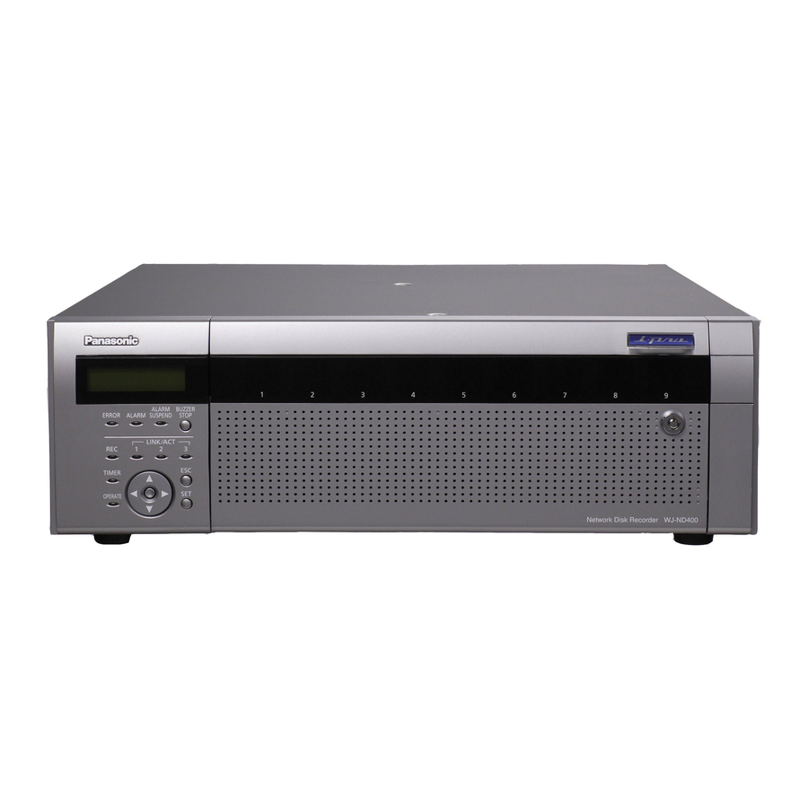
Page 80: Major Operating Controls And Their Functions
Major Operating Controls and Their Functions Front View (9) (10) (11) (12) (13) (14) (15) (16) (1) Error indicator [ERROR] (6) HDD indicators ("HDD1" to "HDD9") Blinks when errors or problems with the recorder's operation HDD access indicator (right side) occur. - Page 81 Major Operating Controls and Their Functions (14) Escape button [ESC] Use to return to the previous screen when doing operations Important: on the LCD. • When the HDD indicators light red in the RAID5/RAID6 mode, quickly replace the HDD where the errors occurred. Contact (15) Link indicators [LINK/ACT] your dealer for information on replacing HDDs.
-
Page 82: Inside The Front Cover
Major Operating Controls and Their Functions Inside the Front Cover (3) (4) (6) (7) (1) USE button [USE] (4) HDD access indicator [A/F] Used when adding or replacing an HDD or changing the Indicates the access status and problems with the HDD. operating mode of the HDD. - Page 83 Major Operating Controls and Their Functions (5) HDD bay slots Up to 9 HDD can be installed (one HDD unit is installed at the factory). Note: • Limiting factors for the RAID5/RAID6 mode. RAID5 mode : The RAID5 mode can be used when more than three HDDs are installed.
-
Page 84: Rear View
Major Operating Controls and Their Functions Rear View (1)(2) (3) (10) (1) Handle for Maintenance (10) Power switch [POWER] Loosen the 5 screws indicated by the triangles and grip these Turns the power on. Press it again to turn the power off and handles to pull off the panel when replacing the fan or doing end operations. -
Page 85: Outline Of Functions
Outline of Functions Description of Functions Mega Pixel Camera Compatibility and HDD Space Management Capacity The HDDs in the recorder are virtually divided in the 4 image areas shown below (refer to the Setup Instructions (PDF file)). The recorder can record high-definition images (mega pixel camera You can set only one area for each HDD. -
Page 86: Hdd Fault Tolerance System
Outline of Functions HDD Fault Tolerance System RAID 6 The RAID function makes it possible to improve the HDD's tolerance to errors. This product is equipped with the RAID6 mode that can recover image data when two HDDs fail, in addition to the RAID5 mode that can recover image data (RAID6 has two sets of error correcting code data). -
Page 87: Recording And Playing Images
: Receives command alarms from PCs via a sent simultaneously to a maximum of 16 PCs. network. Image data • Site Alarm : Receives the Panasonic alarm protocol from network cameras. Network camera Recorder Setting Schedules Schedules can be made so each day can be divided into six time zones, each of which can be programmed separately. -
Page 88: List Of Functions
• Buzzer sounds transmitted to an FTP server. The buzzer sounds according to the settings on the settings • A PC is notified of an alarm according to Panasonic alarm menu. protocol settings. • The camera goes to its preset position. -
Page 89: Network
Outline of Functions Network Connection Examples Remote Operation IP address: IP address: 192.168.0.1 192.168.1.1 The recorder and cameras connected to it can be operated from a subnet mask: subnet mask: PC on the network. 255.255.255.0 255.255.255.0 Router Router Enabled functions WAN* When monitoring images from a camera with pan and tilt function. -
Page 90: Sd Memory Recording
Outline of Functions SD Memory Recording If the connection with the camera is broken within the time set in the program in the recorder, images are recorded on the SD memory card in the camera. Recording Rate Setting SD memory recording can only be set when the camera supports it and the compression format is set to M-JPEG. -
Page 91: Getting Started
Getting Started Installation and Setup Setup Procedure The procedure to start operations is shown below. Rack Mounting Mount the recorder into the rack (page 23). Go to step 2 if you are not using a rack. Connections Connect the recorder to the various devices (page 25). Power On Turn on the recorder (page 39). -
Page 92: Setting Up The Rack
Setting up the Rack Install the recorder in the rack. Rack Mounting Secure using the rack mounting screws. Install the recorder into an EIA standard compliant rack. EIA standard compliant : an EIA-standard 19"rack, depth product 550 mm or more (locally procured) Note: •... -
Page 93: Rack Mounting Positions
Setting up the Rack Rack mounting positions When connecting multiple extension units (WJ-HDE400) to the recorder, place the recorder in the center of the rack. Connect the recorder and the extension unit with the connection cable (1 m {39.4 "}) included with the extension unit (page 31). Connection cable (provided with extension unit) Extension unit... -
Page 94: Connections
Connections This sections explains how to connect the PC, cameras, and extension units. The types of cables and other hardware depend on how each setup is done. Before starting installation work, check to make sure you have everything you need. Connecting the PC and the Camera Connect the PC and the camera to the recorder using a HUB. - Page 95 Connections 2 Port Operation Using a HUB for Direct Connection The PC connects to the camera using the camera port and the client PC port on the rear of the recorder. Network camera LAN cable (Not provided: 10BASE-T / 100BASE-TX / 1 000BASE-T category 5e, straight (NTSC model) / category 7, straight (PAL model)) Recorder...
-
Page 96: Example Of Connectivity With 1 Port Operation
Connections Example of Connectivity with 1 Port Operation Connecting to a PC over ADSL Network camera ADSL router (Commercially available) (Internet) ADSL line LAN cable (Not provided: 10BASE-T / 100BASE-TX / 1 000BASE-T category 5e, straight (NTSC model) / category 7, straight (PAL model)) Recorder Note: •... - Page 97 Connections Connecting multiple units to the recorder Network camera LAN cable LAN cable (Not provided: 10BASE-T / (Not provided: 10BASE-T / 100BASE-TX / 1 000BASE-T 100BASE-TX / 1 000BASE-T category 5e, straight (NTSC model) / category 5e, straight (NTSC model) category 7, straight (PAL model)) category 7, straight (PAL model)) Recorder (1)
-
Page 98: Example Of Connectivity With 2 Port Operation
Connections Example of Connectivity with 2 Port Operation Connecting to a PC over ADSL Network camera Recorder LAN cable (Not provided: 10BASE-T / 100BASE-TX / 1 000BASE-T category 5e, straight (NTSC model) / category 7, straight (PAL model)) (Internet) ADSL line ADSL router (Commercially available) - Page 99 Connections Connecting multiple units to the recorder Network camera Network camera Recorder (1) Recorder (area 1) LAN cable LAN cable (Not provided: 10BASE-T / (Not provided: 10BASE-T / 100BASE-TX / 1 000BASE-T 100BASE-TX / 1 000BASE-T category 5e, straight (NTSC model) / category 5e, straight (NTSC model) / category 7, straight (PAL model)) category 7, straight (PAL model))
-
Page 100: Connecting The Extension Unit
Connections Connecting the Extension Unit You can connect a maximum of 5 extension units to a single recorder. Connect the recorder and the extension unit with the connection cable included with the extension unit. Connect as follows when connecting multiple extension units (WJ-HDE400) or adding a new connection. Also, be sure to read the user manual for the extension unit. -
Page 101: About Connectors
About Connectors Using the Alarm/Control connector You can use emergency recording and auto adjustment time functions when alarm equipment like a buzzer or indicator which is mounted externally. Create the connector by referring to the pin assignments. Pin Assignments The pin assignments are different for other Network Disk Recorders. Connect using the following chart. ALARM/CONTROL Name Description of Operation... -
Page 102: Connectivity For Emergency Recording
About Connectors Name Description of Operation Remarks Number Alarm suspension input The state of alarm suspension is assumed Non-voltage make contact input 5V according to the signal input. pull-up 150 kΩ Outage detection input Start of outage processing according to the signal input. -
Page 103: Auto Adjustment Time Function Connection 2
About Connectors Auto Adjustment Time Function Connection 2 When settings menu - [Basic] - [Time & date] - [Auto adjustment time] is set to [Slave] [Time Adjust Input] is available and the time on the recorder is synchronized with the other devices. 15 minutes before or after the set [Activation time] if a signal output from another device is input to the Adjustment Time I/O, the time on the recorder is set to the [Activation time]. -
Page 104: Uninterruptible Power Supply (Ups) Connectivity
About Connectors Uninterruptible Power Supply (UPS) Connectivity This section explains how to connect an Uninterruptible Power Supply (hereafter UPS) as part of your power outage countermeasures. When the recorder receives a power outage detection signal from the UPS, it begins its internal power off sequence (process to stop recording to protect the recorder). -
Page 105: Using The Alarm Connector
About Connectors Using the Alarm Connector Used to connect alarm-related devices such as a sensor or a door switch. Create the connector by referring to the pin assignments. Pin Assignments The pin assignments are different for other Network Disk Recorders. Connect using the following chart. ALARM Name Description of Operation... -
Page 106: Alarm Connectivity
About Connectors Alarm Connectivity When a signal is input to Alarm Inputs 1 through 32 (Alarm connector pins 1 through 12 and 15 through 25, Alarm/Control connector pins 1 through 9), recording and camera images are shown according to the settings. When alarm devices such as a buzzer or indicator are installed externally, connect them to the Alarm output (Alarm/Control connector pin 21). -
Page 107: Alarm/Control Connector And Alarm Connector Timing And Polarity
About Connectors Alarm/Control connector and Alarm Connector Timing and Polarity Connectors Active Time Remarks Alarm input 100 ms or more L active Alarm output The time set on the setup menu L active Network error output Until the network error is cleared, or until the [ERR] button on L active the operation window (browser) is clicked. -
Page 108: Power Supply
(system check) begins. Set [Basic] - [Basic] - [Recording] on the settings menu • During system check, [WJ-ND400] appears on the LCD. to [Off] and stop all recording (refer to the Setup Also, [Don't turn off] is displayed, followed by [System Instructions (PDF file)). -
Page 109: Using The Front Panel For Operations
Using the Front Panel for Operations Basic Operations Operate the recorder using the LCD and the buttons on the front panel. The LCD changes as follows when you press the arrow buttons (up or down). Date display screen The date, time and internal temperature (reference value) are displayed. Refer to the Setup Instructions (PDF file) for more information. -
Page 110: Checking System Information
Using the Front Panel for Operations Checking System Information For checking information (software version, hardware version, MAC address, or serial number) about the recording system. Check the settings by switching between screens using the following operations. The LCD changes as follows when using the arrow buttons (up or down). Also, pressing the arrow buttons (left or right) from [PT#1 MAC address] switches between the PT#2 and PT#3 screens. -
Page 111: Checking The Ip Address
Using the Front Panel for Operations Checking the IP Address You can check the DHCP, IP address, subnet mask, gateway , and HTTP port for each port. The following ports are displayed: Camera port: PT #1, Client PC port (PC port): PT #2, and the Maintenance port: PT#3. Use the arrow buttons (left or right) to switch between ports. -
Page 112: Setting The Ip Address
Using the Front Panel for Operations Setting the IP Address Settable items are the same as those in "Checking the IP Address (page 42)". Configure the settings for each item by switching between screens using the following operations. When the cursor is ">", use the arrow buttons (up or down) to switch between screens. -
Page 113: Hdd Unit
Using the Front Panel for Operations Install the HDD into the special canister and use the four HDD Unit screws to fasten both sides of the HDD. The torque for tightening the screws is 0.49 N•m (5 kgf•cm) Use the HDD canister provided to install the HDD. (use a torque driver) The HDDs can be easily installed or removed from the HDD slots inside the front cover. -
Page 114: Handling The Hdd
Using the Front Panel for Operations Handling the HDD Install the HDD unit provided (page 46). The HDDs can be easily installed or removed from the HDD bay slots inside the front cover. Contact your dealer for information on purchasing, installing, and replacing HDDs. Important: •... -
Page 115: Installing Hdds
Using the Front Panel for Operations The HDD is automatically recognized. Installing HDDs • While the HDD is being recognized, the HDD status indicator blinks orange. You can install HDDs from the recorder while it is in operation. Once the HDD is recognized, the HDD status indicator lights green or blinks. -
Page 116: Installing Hdds By Unit
Using the Front Panel for Operations Select [YES] with the arrow buttons (left or right) and Installing HDDs by unit then press the [SET] button. All the HDDs in one extension unit can be linked to operate at the same time. For details refer to the operating instructions for the extension unit. -
Page 117: Removing Hdds
Using the Front Panel for Operations Select [YES] with the arrow buttons (left or right) and Removing HDDs then press the [SET] button. You can remove HDD units from the recorder while it is in operation. Select the number of the extension unit where you installed the HDD with the arrow buttons (up or down) Insert the key (included) into the key hole and turn it and press the [SET] button. - Page 118 Using the Front Panel for Operations Select [YES] with the arrow buttons (left or right) and Check the disk information. then press the [SET] button. Check the following content related to the HDD under [Disk information] on the settings menu. Refer to the Setup Instructions (PDF file) for more information.
-
Page 119: Removing Hdds By Unit
Using the Front Panel for Operations Select [YES] with the arrow buttons (left or right) and Removing HDDs by unit then press the [SET] button. The HDDs in one extension unit can be removed simultaneously. For details refer to the operating instructions for the extension unit. The extension unit stop process begins and all the HDD Insert the key (included) into the key hole on the front status indicators blink orange. -
Page 120: Setting The Hdd's Operation Mode
Using the Front Panel for Operations Check the disk information. Setting the HDD's Operation Mode Check the following content related to the HDD under [Disk information] on the settings menu. Refer to the Setup Sets the HDD operation mode. Instructions (PDF file) for more information. The initial setting is set to [SINGLE mode]. -
Page 121: Hdd Error Recovery (During Raid Operation)
Using the Front Panel for Operations HDD Error Recovery (During RAID Operation) When errors occur during RAID5 or RAID6 operation, the HDD errors in the following table are displayed. When one HDD has errors ([1down]) in RAID5 mode, the data on the remaining HDDs can be read and recovery is possible. When two HDDs have errors ([2down]) in RAID6 mode, the data on the remaining HDDs can be read and recovery is possible. -
Page 122: Replacing Faulty Hdd During Raid Operation
Using the Front Panel for Operations Hook the HDD unit's tab securely on the Replacing Faulty HDD during RAID HDD bay slot. Operation Press the lever down and push the HDD When one HDD errors ([1down]) in RAID5 mode, the data on the unit until the removal knob clicks. -
Page 123: Rebooting
Using the Front Panel for Operations Rebooting Press the [SET] button on the Manual Reboot screen to display the Manual Reboot ACCEPT screen. Select [YES] and press the [SET] button to reboot. [SET]... -
Page 124: Troubleshooting
Troubleshooting Attachments Problems Before requesting service, check the following items. Contact your dealer if the problem does not appear here, if the problem is not resolved by these remedies, or if you have any questions about settings and installation. Problem Check item/remedy Page Make sure that the power plug is firmly connected to the electric outlet. - Page 125 Troubleshooting Problem Check item/remedy Page Make sure the HDD unit is firmly inserted into the disk slot. page 53 The HDD you are trying to recover data from has errors. Cannot recover data after replacing Make sure that the capacity of the replaced HDD is not smaller than the HDDs original HDD.
-
Page 126: Specifications
Specifications WJ-ND400 ● General Specifications Power source NTSC model: 120 V AC, 60 Hz PAL model: 220 V - 240 V AC, 50 Hz Power consumption 170 W Ambient operating +5 ºC to +45 ºC {41 °F - 113 °F}... -
Page 127: Accessories
Accessories Standard Accessories • CD-ROM ................ 1 pc. • Installation Guide (this book) ..........1 pc. • Quick Reference Guide ............ 1 pc. • Warranty (Only for NTSC model) ........1 pc. The followings are for installation: • Hard disk unit..............1 pc. •... -
Page 128: Index
Index 1 port operation ..................... 25 1 000BASE-T ....................25 Network error output ................32, 38 100BASE-TX ....................25 Network security ....................20 10BASE-T ..................... 25 2 port operation ..................... 26 Pan & tilt ......................20 Pin assignments ..................32, 36 Accessing Live Images.................. 18 Post-event recording..................19 Active time..................... - Page 129 Directive for the chemical involved. For U.S., Canadian and Puerto Rican fields: For European and other fields: Panasonic System Solutions Company, Matsushita Electric Industrial Co., Ltd. Unit Company of Panasonic Corporation of North America Osaka, Japan www.panasonic.com/business/ http://panasonic.net For customer support, call 1.800.528.6747 Three Panasonic Way 2H-2, Secaucus, New Jersey 07094 Importer’s name and address to follow EU rules:...
- Page 130 Network Disk Recorder Setup Instructions WJ-ND400 Model No. Before attempting to connect or operate this product, please read these instructions carefully and save this manual for future use.
- Page 131 Contents Preface Preface Preface................................5 About these Operating Instructions........................5 System Requirements for a PC ........................6 Trademarks and Registered Trademarks ......................6 Restrictions when operating MPEG-4 images ..............7 Initial configurations Getting started ........................8 Setup procedure ............................... 8 Setup menu list ..............................9 Network settings ........................11 Recorder network settings ..........................
- Page 132 FTP ................................. 56 Mail ................................. 58 Proxy................................60 Network..........................61 Basics ................................61 DDNS................................64 SNMP................................65 Panasonic alarm protocol ..........................66 User management.........................67 Basics ................................67 Administrator..............................68 Users................................69 Editing user information ..........................70 Deleting user information ........................... 70 Hosts................................
- Page 133 Contents Data encryption........................85 Encryption settings............................85 Formatting disks ........................86 Format................................86 Pre-event recording area formatting ....................... 88 Attachments About mail notification ......................90 Alarm mail notification............................. 90 Warning mail notification..........................90 Troubleshooting........................93 Problems................................. 93 Message display ............................. 96 Glossary..........................97 Words used in the manual ..........................97 Index.............................100...
-
Page 134: Preface
Preface The Network Disk Recorder (WJ-ND400) is for recording images and audio from network surveillance cameras to a hard disk (hereafter HDD). It is possible to connect up to 64 cameras over a network. Also, it is possible to access and operate the recorder via a network from the web browser on a computer (hereafter PC). A maximum of 16 PCs can be connected (via a network). -
Page 135: System Requirements For A Pc
System Requirements for a PC It is recommended to operate this unit using a PC that meets the following system requirements. ® ® • OS : Microsoft Windows Vista Business (32-bit) ® ® : Microsoft Windows XP Professional SP2 ® ®... -
Page 136: Restrictions When Operating Mpeg-4 Images
Restrictions when operating MPEG-4 images There are following restrictions when "MPEG-4" is selected for the 4. When recording images image compression method on the setup menu. ("NW camera" (1) Time and date displayed on the recording event list (actual under "Camera") start time of recordings) may not exactly indicate the actual time of recording trigger (event occurrence time, start time of When displaying live images... -
Page 137: Getting Started
Getting started Initial configurations Setup procedure The procedure to start operations is shown below. Rack Mounting Mount the recorder into the rack (refer to the Installation Guide). Go to step 2 if you are not using a rack. Connections Connect the recorder to the various devices (refer to the Installation Guide). -
Page 138: Setup Menu List
Set the SNMP server. page 65 Configure these settings when connecting to an SNMP manager and check the status of the recorder. Panasonic alarm Set to send a message to registered addresses when an event or an error page 66 protocol... - Page 139 Getting started Setting item Description Page User mng. Basic Set whether user and host authentication should be performed. page 67 Administrator Edit registered administrator information such as the administrator name, page 68 password, and start monitor. User Edit or delete registered user information and register uses who can operate page 69 the recorder.
-
Page 140: Network Settings
Network settings Recorder network settings This section explains how to configure recorder network settings. The following are the settings for ports to be used. Set the parameters using the button on the front panel. Setting parameters are displayed on the LCD. Setting item Description DHCP... - Page 141 Network settings The following is the procedure for configuring network settings. Make sure that the Date display screen (standby screen) Press the [ESC] button to move the cursor to ">" and is displayed on the LCD. check the settings. If display is different, press the [ESC] button to display the standby screen.
-
Page 142: Pc Network Settings
Network settings PC network settings This section explains how to match the PC network settings to the settings of the recorder. In order to access the recorder, the IP address of the PC must be set to the same subnet mask area as the recorder client PC port. The examples in this manual are presented using the basic settings of Windows XP. - Page 143 Network settings Click [Internet Protocol (TCP/IP)] and then click [Properties]. This will display the [Internet Protocol (TCP/IP) Properties] window. Click [Use the following IP address] and then configure the IP address and subnet mask. • For the IP address, set the same subnet mask area as the recorder.
-
Page 144: About Operating Windows
About operating windows Display and close the operating window Operate the recorder from a web browser on a PC. Start the PC. Enter a "User name" and "Password" that is registered with the recorder, and click the [Login] button. The top page is displayed. Launch the web browser. - Page 145 Follow the on-screen instructions. • If WJ-ND200/WJ-ND300 ActiveX is already installed, delete WebVideo ActiveX using Add or Remove Programs and then install WJ-ND400 ActiveX. • When the install wizard is displayed again even after completing the installation of the ActiveX, restart the PC.
-
Page 146: Names And Functions Of Components
About operating windows Names and functions of components Top page (1) [Control] button (page 18) (8) [HDD] tab (page 22) Performs operations such as searching for recorded images. Controls recorded images, such as playing images or You can also perform the functions of the camera picture downloading to save to a PC. -
Page 147: [Control] Button
About operating windows (4) [Search] box [Control] button [Search] button The following operation panel appears when you click the [Control] Searches for recorded images. The search results are shown button. on the rec event list window. (refer to the Operating Instructions (PDF file)) [Area select] button Selects disk to play or search. -
Page 148: [Cam. Select] Button
: 4x (4) [Cam. select] box Displays the group titles of the cameras connected to the recorder when clicking [WJ-ND400]. Refer to page 52 for information about group settings. Displays the cameras the belong to that group when clicking a group title. Displays the image of camera when clicking a... -
Page 149: [Setup] Button
About operating windows (7) [Server] button [Setup] button Displays a menu for setting the server. The following operation panel appears when you click the [Setup] (8) [Network] button button. Displays a menu for setting the network. (9) [User mng.] button Displays a menu for setting authentication. -
Page 150: Status Display Area
About operating windows Status display area (1) Displays the status of live and playback (2) [REC] indicator images. Displays the recording status. : Live images are being displayed. : Recording is being performed. : Recorded images are being played back. : Recording is not being performed. -
Page 151: Playback Point Operation Area
About operating windows Playback point operation area (1) Displays the time and date for the download (2) [Go to date] button start point/ending point. Used to playback images from a specified time and date. [Start] : Set the time and date to start the image (3) [Go to last] button to be downloaded. - Page 152 About operating windows Note: • The operations are as follows when the image for playback is an MPEG-4 image. Date/Time Search : Playback may start a few seconds before or after the specified time. Reverse Playback : Not all recorded images are displayed.
-
Page 153: [Cam] Tab
About operating windows [CAM] tab The camera can be controlled (pan/tilt, zoom, focus, brightness, preset, auto mode) when the live image is from a camera that can pan and tilt. Some camera operations cannot be done depending on the type of camera connected. (1) [Zoom] box Click [-] or [+] to adjust the zoom. -
Page 154: Basic Operations
About operating windows Basic operations Display the top page and access the recorder. Configure the settings for each item. Click the [Set] button after configuring the settings. The settings are reflected on the recorder. • The changes are canceled if you move to another page without clicking the [Set] button. -
Page 155: Quick Settings
Quick settings Setup Configure the language, time & date, network setup, camera registration, and the minimum required settings to operate the recorder. Settings Language, and time & date settings This section explains how to configure settings for the display language, and the current time and date. Click the [Quick] button on the setup menu. -
Page 156: Network Setup
Quick settings Network setup This section explains how to configure recorder network settings. Click the [Quick] button on the setup menu. Under the "Network setup" item, click the [Set] button This will display the setting window. When you change the Client PC port IP address, the "Change IP Address"... -
Page 157: Camera Registration
Quick settings Camera registration This section explains how to register a camera on the recorder. The recorder supports registration of up to 64 cameras. Click the [Quick] button on the setup menu. Click the [Registration] button. This will display the setup window. This will display a camera registration confirmation message. - Page 158 Quick settings Click the [OK] button. This completes registration. Important: • Execute [Register the IP address automatically given by this unit to a detected camera] to automatically provide IP addresses to all detected cameras. Note that some cameras may already be operating. Note: •...
-
Page 159: Program Settings
Quick settings Program settings Use the following procedure to select the recording program that determines the live image rate, recording rate, and other operations. Click the [Quick] button on the setup menu. Configure the settings for each item. This will display the setting window. Refer to “Quick settings 4”... -
Page 160: Basics
Basics Configure the system settings to operate the recorder. Basics Use the following procedure to configure basic system settings. Click the [Basic] button on the setup menu. Configure the settings for each item. Refer to “Basic setup” table for details about the settings. On the sub-menu that appears, click [Basic]. -
Page 161: Time & Date
Basics Time & date Use the following procedure to set the current time and date. Click the [Basic] button on the setup menu. Configure the settings for each item. Refer to “Time display format” table for details about the settings. On the sub-menu that appears, click [Time &... - Page 162 Basics Item Settings Description Activation time 0♦ to 23 Specifies the time for auto time adjustment. • When [Slave] is selected for [Auto adjustment time], this setting specifies the time that the recorder's time is auto adjusted. • When [Master] is selected for [Auto adjustment time], this setting specifies the time that the time setting is output from the alarm/control terminal.
-
Page 163: Emergency Recording
Emergency recording Emergency recording Sets the recording duration or recording rate when performing emergency recording by input of the emergency recording input signal. For details about emergency recording, refer to the Installation Guide. Click the [Emergency rec.] button on the setup menu. Configure the settings for each item. - Page 164 Emergency recording Item Settings Description Audio rec. Off♦ / On Specifies whether to record audio images. (Audio recording) • Audio and images are recorded at the same time. Audio recording without image is not supported. • Audio recording can be selected only for a camera model that supports audio recording.
-
Page 165: About The [Measurement] Button
Emergency recording About the [Measurement] button Note: • When the recording rate for SD memory recording is set, be By clicking the [Measurement] button, you can check that the sure to set to use recording to the SD memory card in the specified rates provide proper operation on the network. -
Page 166: Event
• A PC is notified of an alarm according to Panasonic alarm recorder. protocol settings When an event or error occurs, a PC is automatically notified •... -
Page 167: Basics
Event Basics Use the procedures in this section to configure alarm output duration and buzzer duration settings for when an event (site alarm, terminal alarm, command alarm) occurs. Click the [Event] button on the setup menu. Configure the settings for each item. Refer to “Basic event settings”... -
Page 168: Terminal Alarm
Event Terminal alarm Use the following procedure to configure settings the control alarm action when a terminal alarm occurs. For information on how to register preset positions for the camera, refer to the Operating Instructions. Click the [Event] button on the setup menu. Configure the settings for each item. -
Page 169: Site Alarm
Event Site alarm Use the following procedure to configure settings that control terminal alarm action when a Panasonic alarm protocol alarm (site alarm) is sent from a camera. Click the [Event] button on the setup menu. Configure the settings for each item. -
Page 170: Command Alarm
Event Command alarm Use the following procedure to configure settings that control command alarm action when an event occurs. Click the [Event] button on the setup menu. Configure the settings for each item. Refer to “Command alarm settings” table for details about the settings. -
Page 171: Schedules
Schedules Create a schedule by specifying the day and time to record. Program Use the procedure in this section to create a recording program that controls live images, the recording rate, etc. You can create up to eight recording programs on the recorder. Click the [Schedule] button on the setup menu. - Page 172 Schedules Program settings Item Settings Description Model Shows the model number of the selected camera. Compression Shows the compression format of the recorded image. • To change the compression format, refer to "NW camera (page 48)". Measurement Max. network speed (Mbps) Shows the maximum bit rate on the network being used when the [Measurement] button is clicked.
- Page 173 Schedules Item Settings Description *1*2*3 Duration 2s / 5s / 10s / 20s / 30s / 1min / Specifies the time of post-event recording. 2min / 3min / 5min / 10min / 15min • When [Manual] is selected, recording is performed only / Manual / Continue while the alarm signal is being input.
-
Page 174: About The [Measurement] Button
Schedules About the [Measurement] button Clicking the [Measurement] button displays a window that you can use to confirm that the specified rates provide proper operation on the network being used. A red rate setting value indicates that live images or recording of the image may not be possible at the specified rate. -
Page 175: Time Table
Schedules Time table Use the procedure in this section to configure time table settings to schedule recording operations for each day of the week, and to assign each time table to a recording program. You can configure up to six time tables, for specific days of the week. You also can configure settings for externally controlled recording. -
Page 176: About Externally Controlled Recording
Refer to the "readme.txt" file on the CD-ROM for details about the software. Note: • If an alarm occurs, alarm message, Panasonic alarm protocol, and alarm mail operate even if they are off. About externally controlled recording Special days Connecting an external switch to the recorder makes it possible... -
Page 177: Camera
Camera Configure the network settings (address, ports etc.) and group settings, and sequence operations for the cameras. NW camera Use the procedures in this section to register and modify network cameras. Automatically detecting and registering cameras Click the [Camera] button on the setup menu. Find the camera you want to register, and check if its check box under "Camera search"... - Page 178 Camera NW camera settings 1 Item Settings Description Model Shows the model number of a detected camera. MAC address Shows the MAC address of the camera. IP address Shows the IP address of the camera. New IP address Address input Enter a new IP address to assign it to a camera.
-
Page 179: Switch Cameras (4-Screen Display Setting)
Camera Switch cameras (4-screen display Checking and changing a camera setting) (Manually setting) Click the [Camera] button on the setup menu. Click the [Camera] button on the setup menu. Click the [NW camera] tab. Click the [NW camera] tab. This will display the "NW camera setup" window. This will display the "NW camera setup"... - Page 180 Click the [Set] button. NW camera settings 2 Item Settings Description Manufacturer Panasonic♦ / Axis Specifies the camera manufacturer. Model/Compression --♦ Specifies the camera model and image compression format. Model/JPEG Refer to the "readme.txt" file on the CD-ROM for details about Model/M-JPEG camera's model number.
-
Page 181: Group
Camera Group Use the following procedure to specify the group title of a camera. Click the [Camera] button on the setup menu. Input a group title. Refer to “Group settings” table for details about the settings. Click the [Group] tab. This will display the "Group Setting"... -
Page 182: Sequence
Camera Sequence Use the following procedure to configure settings for automatically switching the camera image in a preset sequence. Click the [Camera] button on the setup menu. Click the [Sequence] tab. This will display the "Sequence Setting" window. Configure the settings for each item. Refer to “Sequence display type settings”... - Page 183 Camera Sequence display type settings Item Settings Description Sequence display type 1-screen♦ / 4-screen Selects 1-screen or 4-screen during sequence display. ♦Initial default 1-screen live sequence Item Settings Description Cam. Cam.1 to Cam.64 / -- Specifies the camera images displayed for each step. •...
-
Page 184: Server
Server Configures settings for clock adjustment based on an NTP (Network Time Protocol) server. Click the [Server] button on the setup menu. Configure the settings for each item. Refer to “NTP settings” table for details about the settings. On the sub-menu that appears, click [NTP]. This will display the "NTP Setup"... -
Page 185: Ftp
Server Use the following procedure to send images from a camera connected to the recorder to a specified FTP server. Click the [Server] button on the setup menu. Configure the settings for each item. Refer to “FTP settings” table for details about the settings. On the sub-menu that appears, click [FTP]. - Page 186 Server Item Settings Description Image transmission by alarm Set the following items to transmit images of where an alarm occurs at an event. Setting whether or not to transmit live images to the FTP server where an alarm occurs at an event can be set for scheduled time periods with "Time table (page 46)".
-
Page 187: Mail
Server Mail Use the following procedure to configure settings for sending alarm mail and for warning mail notification. Click the [Server] button on the setup menu. Configure the settings for each item. Refer to “Mail settings” table for details about the settings. On the sub-menu that appears, click [Mail]. - Page 188 Server Mail settings Item Settings Description Attach alarm image Off♦/On Specifies whether the image when the event occurred should be attached to the mail. • Image attachment is not supported when the compression format specified for the camera image being sent is MPEG- •...
-
Page 189: Proxy
Server Proxy Use the following procedure to configure settings to use the proxy server. Click the [Server] button on the setup menu. Configure the settings for each item. Refer to “Proxy settings” table for details about the settings. On the sub-menu that appears, click [Proxy]. This will display the "Proxy setting"... -
Page 190: Network
Network Basics This section explains how to configure recorder network settings. Configure network configuration settings like the IP address, default gateway and DNS (Domain Name System) server. Click the [Network] button on the setup menu. Click the [Set] button. On the sub-menu that appears, click [Basic]. Click the port forwarding [Setup >>] button. - Page 191 Network Network settings Item Settings Description NW link down detection Off♦ / On Specifies whether to detect disconnected network connection of Camera port/Client PC. Bandwidth control Unlimited♦ / 32Kbps / 64Kbps / Specifies the maximum rate for data transmitted to the network. 128Kbps / 256Kbps / 512Kbps / •...
- Page 192 Network ♦Initial default Refer to "Recorder network settings (page 11)" for information on initial default settings. Important: • A different subnet should be set for each port. • If DHCP is set to [On] and "SD Memory recording" is set, write requests to the camera's SD memory data may fail at startup. This occurs because the response from the DHCP server is slow.
-
Page 193: Ddns
Network DDNS Use the following procedure to configure settings for using a DDNS (Dynamic Domain Name System). Click the [Network] button on the setup menu. Configure the settings for each item. Refer to “DDNS settings” table for details about setting items. On the sub-menu that appears, click [DDNS]. -
Page 194: Snmp
Network SNMP Use the following procedure to configure settings for using SNMP (Simple Network Management Protocol). Configure these settings when connecting to an SNMP manager and check the status of the recorder. Click the [Network] button on the setup menu. Configure the settings for each item. -
Page 195: Panasonic Alarm Protocol
Item Settings Description Port number (to PC) Port number input (1818♦) Enter the port number to be used for Panasonic alarm protocol. Retry 1 to 30 (2♦) Specifies the number of retries when sending to the PC is unsuccessful. Destination address... -
Page 196: User Management
User management Configure the user and host authentication required to access the recorder from a PC. It is possible to restrict access by users and hosts (PCs). Basics Use the following procedure to specify whether user and host authentication should be performed. Click the [User mng.] button on the setup menu. -
Page 197: Administrator
User management Administrator Use the following procedure to configure settings to assign recorder administrator privileges to a user (administrator). The administrator name and password can be changed, and the operation level and other operation privileges can be configured. Click the [User mng.] button on the setup menu. Configure the settings for each item. -
Page 198: Users
User management Users Use the following procedure to configure information (user name, password, operation level, etc.) about recorder users. Up to 32 users can be registered. Click the [User mng.] button on the setup menu. Configure the settings for each item. Refer to “User setups”... -
Page 199: Editing User Information
User management Note: • Clicking the [Registration] button does not log out other users. Editing user information Deleting user information Click the [User mng.] button on the setup menu. Click the [User mng.] button on the setup menu. On the sub-menu that appears, click [User]. On the sub-menu that appears, click [User]. -
Page 200: Hosts
User management Hosts The following procedure is to register information for PCs (hosts) that can access the camera over a network. Up to 32 hosts can be registered. Click the [User mng.] button on the setup menu. Configure the settings for each item. Refer to “Host settings”... -
Page 201: Editing Host Information
User management Editing host information Deleting host information Click the [User mng.] button on the setup menu. Click the [User mng.] button on the setup menu. On the sub-menu that appears, click [Host]. On the sub-menu that appears, click [Host]. This will display the "Host setting"... -
Page 202: User Level
User management User level Use the following procedure to define which operations can be performed at each user level. You can specify functions that can be accessed at each user level (LV1/LV2/LV3/LV4). Click the [User mng.] button on the setup menu. Configure the settings for each item. - Page 203 User management User level settings Item Settings Description *1*2 *3*4 Setup Checked / Unchecked Modification of some settings ([Basic], [Emergency rec.], [Event], [Schedule], [Config.]) allowed in setup menu display. *2*3*4 Quick Checked / Unchecked Modification of setup menu [Quick] settings allowed. *2*3*4 Camera Checked...
-
Page 204: Maintenance
Maintenance Check the recorder and network status, and configure HDDs. Recorder information Use the following procedure to view software and hardware versions, MAC address, serial number, internal temperature, and Extension unit software version information. Click the [Maintenance] button on the setup menu. Check the items you want. -
Page 205: Disk Information
Maintenance Disk information Use the following procedure to view the capacities of the HDDs and Extension units (Ext.1 to 5), the capacity of each recording area, and other disk partition information. You also can view the remaining HDD capacity, the time and date ranges of images recorded on the HDD, and the HDD operating time (hour meter). - Page 206 Maintenance Disk information Item Description Recording Information Clicking the [Display] button displays the capacity, hour meters, and recorded image time and date ranges for each HDD. • Shows HDD1 information when RAID5/RAID6 is operating. Operational mode Shows the recorder operation mode. HDD Operational mode: Single mode/RAID5 mode/RAID6 mode Total capacity Shows the sum of the capacities of all the HDDs.
-
Page 207: Network Information
Maintenance Network information Use the following procedure to view each recorder's IP address, and the line speed, number of users logged in, and other network information. Click the [Maintenance] button on the setup menu. Check the items you want. Refer to “Network information” table for details about the settings. -
Page 208: Disk
Maintenance Disk Use the following procedure to configure settings for operation when the HDD in the recorder becomes full. It also can be used to configure the warning operation when the HDD becomes full. Click the [Maintenance] button on the setup menu. Configure the settings for each item. -
Page 209: Deleting Image Data From A Disk
Maintenance Deleting image data from a disk Use the following procedure to delete image data from the HDD of the recorder. There are two methods available for deletion: auto delete and manual delete. Click the [Maintenance] button on the setup menu. Configure the settings for each item. -
Page 210: Settings Management
Maintenance Settings management Use the following procedure to save setup menu settings to the recorder and to load previously saved settings. This procedure also can be used to return setup menu settings to their initial defaults. Click the [Maintenance] button on the setup menu. Click the button of the respective item to suit your particular requirements. -
Page 211: Configuring Disks
Configuring disks Disk management Display disk configuration to do operations to the HDD. With disk configuration, it is possible to check the total HDD capacity and the capacity of each recording area, and to format HDDs. HDD space management The HDDs in the recorder are virtually divided in the 4 image areas shown below. -
Page 212: Disk Partition Information
Configuring disks Disk partition information Important: • When the "Config" page is displayed, all operations (recording, playback, etc.) except disc configuration stop. • Displaying the config window forcibly logs out any other users currently logged in to the main unit. Also installing or removing HDD or HDD units from the front panel forcibly logs out any other users logged in to the main unit. - Page 213 Configuring disks Disk information Item Description Operational mode Shows the recorder operation mode. HDD Operational mode: Single mode/RAID5 mode/RAID6 mode Total capacity Shows the sum of the capacities of all the HDDs. Normal recording area Shows the storage area capacity of images recorded by manual recording and schedule recording. Event recording area Shows the storage area capacity of images recorded by emergency recording and post-event recording.
-
Page 214: Data Encryption
Data encryption Encryption settings The image and audio data recorded on the HDDs is encrypted. The image and audio data on the HDDs cannot be played except on the recorder when encryption is enabled. Important: • When the "Config" page is displayed, all operations (recording, playback, etc.) except disc configuration stop. •... -
Page 215: Formatting Disks
Formatting disks When necessary, format HDDs when using them for the first time after replacing or adding HDDs, or when connecting an extension unit. HDDs can be formatted as a group or individually (select units when running RAID5 or RAID6). You must also divide the HDD into the normal recording area, event recording area, copy area and the play recording area. - Page 216 Formatting disks Click the [OK] button. This will return to the "Format" window. Click the [Main] button. This will return to the “Cam. select” window. Note: • Multiple recording areas cannot be allocated to a single HDD. • The copy area can be allocated to an HDD plugged into the main unit's HDD8 or HDD9 positions only during single operation.
-
Page 217: Pre-Event Recording Area Formatting
Formatting disks Pre-event recording area formatting Use the following procedure to format a pre-event recording area. Pre-event recording area space can be allocated for each camera channel. • Formatting the pre-event recording area may take around 10 minutes depending on the number of cameras. Important: •... - Page 218 Formatting disks Select the HDD you want to format as the HDD to set with a pre-event recording area, and then click the [Set] button. This will display a window for allocating pre-event recording area. Select the camera channel and enter the amount of space to be allocated.
-
Page 219: About Mail Notification
About mail notification Attachments Alarm mail notification The main unit's address appears in the alarm mail as shown below. Contents of the alarm mail ND400 (192.168.0.250), alarm was occurred. Alarm date: xx-xxx-xxxx xx:xx:xx GMT xx:xx (Example: 01-JAN- 2008 GMT+0:00) Cause of alarm: Displays an event type and a camera channel or an alarm number (Example: COMMAND ALARM 5CH) File name of alarm image: The file name of the image attached to an e-mail. - Page 220 About mail notification Item Description RAID5 recovery failure Recorder: MAIN RAID5 RECOVERY FAILURE Extension unit: EXTx RAID5 RECOVERY FAILURE x is unit number. RAID6 recovery failure Recorder: MAIN RAID6 RECOVERY FAILURE Extension unit: EXTx RAID6 RECOVERY FAILURE x is unit number. Fan trouble Recorder: MAIN FANy ERROR Extension unit: EXTx FANy ERROR...
- Page 221 About mail notification Item Description RAID6 mode format failure Recorder: MAIN RAID6 FORMAT ERROR Extension unit: EXTx RAID6 FORMAT ERROR x is unit number. HDD remove error Recorder: MAIN-y SWAP WARNING Extension unit: EXTx-y SWAP WARNING x is unit number, y is disk number. Alteration detected ALTERED **CH ** is camera channel.
-
Page 222: Troubleshooting
Troubleshooting Problems Before requesting service, check the following items. Contact your dealer if the problem does not appear here, if the problem is not resolved by these remedies, or if you have any questions about settings and installation. Problem Check item/remedy Page Check if the 10BASE-T, 100BASE-TX, or 1000BASE-TX cable is connected −... - Page 223 Troubleshooting Problem Check item/remedy Page This may be caused by the combination of the PC's display adapter and driver. When this happens, first, update the driver of the display adapter. • If this does not resolve the problem, use the following procedure to adjust the hardware accelerator function.
- Page 224 Troubleshooting Problem Check item/remedy Page Check the settings for [NW camera] on the setup menu. page 48 Check the settings for "Live video" on the setup menu. page 42 Check the IP address, subnet mask, and default gateway for the recorder page 61 and the network camera.
-
Page 225: Message Display
Troubleshooting Message display The following problems may occur depending on the operating environment. If these problems occur, use the appropriate remedy to solve it. The following remedies do not affect other applications or security. The "Information bar" used in the following problems and remedies indicates the message bar that appears under the address bar in Internet Explorer. -
Page 226: Glossary
Glossary Disk Configuration Words used in the manual Configure the HDD after replacing, removing, or adding a HDD. Disk Configuration is the menu for configuring the HDD. This manual uses the following words. Electronic Zoom ActiveX Control Enlarges live images and playback images during playback. The A software module developed by Microsoft. - Page 227 Glossary IP Masquerading PoE (Power over Ethernet) A technology for sharing a single global address between two or A technique for supplying power and data simultaneously over an more PCs. Allows simultaneous connection of multiple machines to Ethernet cable. PoE was standardized in June, 2003 as 1 global address to dynamically convert NAT and different TCP/UDP "IEEE802.3af".
- Page 228 Glossary Resolution Subnet mask Indicates the smoothness of the image quality and the size of the Subnet mask consists of 32-bit numeric values. According to the images recorded from the camera. Indicates the number of dots values, devices can determine which part of the address is the used in the image displayed on the screen.
-
Page 229: Index
Disk information..................... 76 Disk partition information................83 Operation mode ..................77, 84 Domain name ....................62 Duration-Post ....................57 Panasonic alarm protocol ................66 Duration-Pre ....................57 Password ..............15, 31, 56, 64, 68, 69, 85 Playback point operation area ...............22 Editing host information................. 72 POP server address ..................59... - Page 230 Index Serial number ....................75 Server address ....................60 Server directory ..................56, 57 Settings management ................... 81 Setup tab ....................... 20 Site alarm ...................... 40 SMTP server address..................59 SNMP ......................65 Special days ....................47 Status display ....................21 Subnet mask ..................
- Page 231 Directive for the chemical involved. For U.S., Canadian and Puerto Rican fields: For European and other fields: Panasonic System Solutions Company, Matsushita Electric Industrial Co., Ltd. Unit Company of Panasonic Corporation of North America Osaka, Japan www.panasonic.com/business/ http://panasonic.net For customer support, call 1.800.528.6747 Three Panasonic Way 2H-2, Secaucus, New Jersey 07094 Importer’s name and address to follow EU rules:...
- Page 232 Notes on handling HDD Be aware of the following at HDD installation and recovery: The network disk recorder, WJ-ND400, is described as ND400 and the extension unit, WJ-HDE400, as HDE400. <Notes for HDD installation> If an HDD unit is added during the operation described below, the ND400 and HDE400 do not recognize the HDD unit to be added.
- Page 233 VMD Number of PCs cameras transmission rate search use * Measured values shall be used at 128 Mbps or less of the bit rate. (Refer to the Setup Instructions (PDF)) * T he setting for PC is described at the case of 4-screen display. The total rate of recording, playing, and live image transmission shall be 200 Mbps or less. * R efer to the operating instructions of the camera for how to set the VMD search. Notes on network connection To connect between ND400 and PCs or between ND400 and cameras, use a gigabit-ready HUB. Failure to observe this may cause unrecorded images that should be recorded, undisplayed live images that should be displayed, unissued alarms that should be issued, etc. resulting in collapsed live images or playback images. See More Panasonic Manuals www.voicesonic.com 3TU001963AAB N0608-0/1 Phone: 877.289.2829...
Need help?
Do you have a question about the WJ-ND400 and is the answer not in the manual?
Questions and answers