
Subscribe to Our Youtube Channel
Related Manuals for Nilfisk-ALTO SC100


Summary of Contents for Nilfisk-ALTO SC100
- Page 1 SC100 - SCRUBTEC 130 Service Manual Nilfisk SC100, 107408100 - 107408102 - 107408103 Nilfisk Alto Scrubtec 130, 107408140 - 107408150 - 107408152 English 04/2015 (1) Form No. 107415442...
-
Page 2: Table Of Contents
Service Manual – SC100 - Scrubtec 130 Table of Contents Table of Contents General Information Machine General Description Service Manual Purpose and Field of Application Other Reference Manuals Conventions Service and Spare Parts Serial Number Label Safety Visible Symbols on the Machine... -
Page 3: General Information
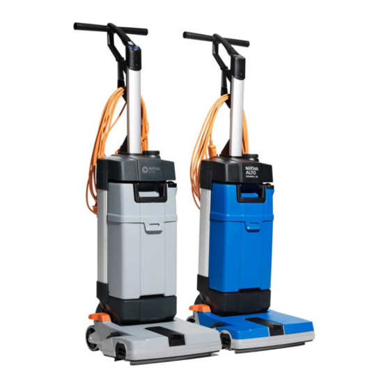
General Information General Information Machine General Description SC100 and Scrubtec 130 are commercial machines for cleaning (scrubbing and drying) smooth and compact floors. The scrubber-dryer can be used to clean carpets or fitted carpet only when the specific accessories in- stalled... -
Page 4: Conventions
Service Manual – SC100 - Scrubtec 130 General Information Conventions In this Manual, forward, backward, front, rear, left or right are intended with reference to the operator’s posi- tion when using the machine Service and Spare Parts Service and repairs must be performed only by authorised personnel or Nilfisk Service Centers. The authorised personnel is trained directly at the manufacturer’s premises and has original spare parts and accessories... -
Page 5: Safety
Service Manual – SC100 - Scrubtec 130 General Information Safety The following symbols indicate potentially dangerous situations Always read this information carefully and take all necessary precautions to safeguard people and property The operator’s cooperation is essential in order to prevent injury No accident prevention program is effective... -
Page 6: General Instructions
Service Manual – SC100 - Scrubtec 130 General Information General Instructions Specific warnings and cautions to inform about potential damages to people and machine are shown below. Danger! • • Before performing any maintenance, repair, cleaning or replacement procedure disconnect the plug from the electrical mains •... - Page 7 Service Manual – SC100 - Scrubtec 130 General Information • Close attention is necessary when used near children • Use only as shown in this Manual. Use only Nilfisk’s recommended accessories. • Check the machine carefully before each use, always check that all the components have been assembled before use If the machine is not perfectly assembled it can cause damages to people and properties •...
-
Page 8: Sc100 Nomenclature
Service Manual – SC100 - Scrubtec 130 General Information SC100 Nomenclature Handle 15. Brush engagement/disengagement lever Main switch 16. Brush Start/stop switch 17. Squeegee bars Solution switch, level 1 18. Inspection lid Solution switch, level 2 19. Recovery water vacuum hose Empty solution tank warning LED 20. -
Page 9: Scrubtec 130 Nomenclature
Service Manual – SC100 - Scrubtec 130 General Information Scrubtec 130 Nomenclature Handle 14. Brush engagement/disengagement lever Start/stop switch 15. Brush Solution switch 16. Squeegee bars Power supply cable with connector 17. Inspection lid Serial number plate/technical data/conformity 18. Recovery water vacuum hose certification 19. -
Page 10: Technical Data
Service Manual – SC100 - Scrubtec 130 General Information Technical Data Model SC100 - Scrubtec 130 Solution tank capacity 3 liters Recovery tank capacity 4 liters Machine size (length x width x height) 400 x 360 x 1,150 mm Cleaning width... -
Page 11: Troubleshooting
Service Manual – SC100 - Scrubtec 130 General Information Troubleshooting Trouble Possible Causes Remedy The machine does not work. The power supply cable or the relevant plug is broken. Replace the cable. The main switch is broken. Replace the switch. -
Page 12: Electrical System
Service Manual – SC100 - Scrubtec 130 Electrical System Electrical System General Wiring Diagram SC100 Parking position Solution Tank Level User Interface (Microswitch) (Reedswitch) PCBA NEO P2 Solution SOLENOID 230V Pump MOTOR Motor Cable Power Supply Switch (Main) Scrubtec 130... -
Page 13: Function Board Connections
Service Manual – SC100 - Scrubtec 130 Electrical System Function Board Connections • (A) Power supply connection (blue cable) • (B) Split power supply connection (brown cable) - Main motor (black cable). • (C) Main motor connection (black cable) • (D) Dosing pump connection (4-way connector - 2 cables). -
Page 14: Removal And Installation
Service Manual – SC100 - Scrubtec 130 Electrical System Removal and Installation Motor Disassembly/Assembly Disassembly Set the machine to stop position Make sure that the machine power supply cable is disconnected from the electrical mains Remove the brush Remove two squeegee bars... - Page 15 Service Manual – SC100 - Scrubtec 130 Electrical System Motor Disassembly/Assembly (Continues) 11 With a screwdriver slightly separate the trigger lever (G) from the track (H), then lift the front side (I) of the cover (J) 12 Remove the cover (J) by disengaging its fasteners (K) from the machine...
- Page 16 Service Manual – SC100 - Scrubtec 130 Electrical System Motor Disassembly/Assembly (Continues) 15 On the left side of the machine, lift the half clamp (M) from the front side (N) and disengage the inner fastener (P), then remove it by disengaging the rear fastener (Q)
- Page 17 Service Manual – SC100 - Scrubtec 130 Electrical System Motor Disassembly/Assembly (Continues) 18 Disconnect the belt (Z) from the motor ring gear 21 On both sides of the machine, remove the screws (AA) (AE), then remove the columns (AF) from the...
- Page 18 Service Manual – SC100 - Scrubtec 130 Electrical System Motor Disassembly/Assembly (Continues) Note: Keep and store the lap of the dosing pump hoses by repositioning the hoses as shown in figure. Dosing Pump From the Solution Filter To the brush deck...
- Page 19 Service Manual – SC100 - Scrubtec 130 Electrical System Motor Disassembly/Assembly (Continues) 23 If necessary, loosen the fastening screw (AM) and remove the parking position microswitch (AL) with the wiring harness 24 If necessary, disconnect the hose (AP) and the hose (AQ) then remove the dosing pump (AN) Retrieve...
- Page 20 Service Manual – SC100 - Scrubtec 130 Electrical System Motor Disassembly/Assembly (Continues) 26 Remove the screw (AV) and remove the case (AW) Retrieve the inner gasket (AX) 27 Remove the fastening screws (AY) of the case (AZ) Remove the screw (BA) and remove the grille (BB)
- Page 21 Service Manual – SC100 - Scrubtec 130 Electrical System Motor Disassembly/Assembly (Continues) Assembly 29 Assemble the components in the reverse order of disassembly, and note the following: ◦ When reinstalling the motor assembly (BD) on the machine deck (BE), place both side bushings (BF) by engaging their notches (BG) in the relevant housings (BH) ◦...
-
Page 22: Function Electronic Board Disassembly/Assembly
Service Manual – SC100 - Scrubtec 130 Electrical System Function Electronic Board Disassembly/Assembly Disassembly Set the machine to stop position Make sure that the machine power supply cable is disconnected from the electrical mains Remove the tank assembly Remove the screws (A) -
Page 23: Switch Panel Disassembly/Assembly
Service Manual – SC100 - Scrubtec 130 Electrical System Switch Panel Disassembly/Assembly Disassembly Set the machine to stop position Make sure that the machine power supply cable is disconnected from the electrical mains Remove the screws (A) fastening the switch panel (B) -
Page 24: Parking Position Microswitch Disassembly/Assembly
Service Manual – SC100 - Scrubtec 130 Electrical System Parking Position Microswitch Disassembly/Assembly Disassembly Set the machine to stop position Make sure that the machine power supply cable is disconnected from the electrical mains Remove the brush Remove two squeegee bars... - Page 25 Service Manual – SC100 - Scrubtec 130 Electrical System Parking Position Microswitch Disassembly/Assembly (Continues) 11 With a screwdriver slightly separate the trigger lever (G) from the track (H), then lift the front side (I) of the cover (J) 12 Remove the cover (J) by disengaging its fasteners (K) from the machine...
- Page 26 Service Manual – SC100 - Scrubtec 130 Electrical System Parking Position Microswitch Disassembly/Assembly (Continues) 15 On the left side of the machine, lift the half clamp (M) from the front side (N) and disengage the inner fastener (P), then remove it by disengaging the rear fastener (Q)
- Page 27 Service Manual – SC100 - Scrubtec 130 Electrical System Parking Position Microswitch Disassembly/Assembly (Continues) 18 Disconnect the belt (Z) from the motor ring gear (AA) 19 Disconnect the solution hose (AB) from the fitting (AC). 20 Release and remove the nozzlehead (AD)
- Page 28 Service Manual – SC100 - Scrubtec 130 Electrical System Parking Position Microswitch Disassembly/Assembly (Continues) 23 Loosen the fastening screw (AM) and remove the parking position microswitch (AL) with the wiring harness Assembly 24 Assemble the components in the reverse order of disassembly...
-
Page 29: Solution System
Service Manual – SC100 - Scrubtec 130 Solution System Solution System Maintenance and Adjustments Cylindrical brush, brush compartment and dosing bridge cleaning Lower the machine to reach the lower side of the cleaning deck Turn the lever (A) counter-clockwise and remove the brush Clean and wash the cylindrical brush with water and detergent Check the brush bristles for integrity and wear;... -
Page 30: Removal And Installation
Service Manual – SC100 - Scrubtec 130 Solution System Removal and Installation Disassembly/assembly of the solution level sensor (inside the tank) Disassembly Set the machine to stop position Make sure that the machine power supply cable is disconnected from the electrical mains... -
Page 31: Disassembly/Assembly Of The Sensor Receiving The Solution Level
Service Manual – SC100 - Scrubtec 130 Solution System Disassembly/assembly of the sensor receiving the solution level Disassembly Set the machine to stop position Make sure that the machine power supply cable is disconnected from the electrical mains Remove the tank assembly... -
Page 32: Dosing Pump Disassembly/Assembly
Service Manual – SC100 - Scrubtec 130 Solution System Dosing pump Disassembly/Assembly Disassembly Set the machine to stop position Make sure that the machine power supply cable is disconnected from the electrical mains Remove the brush Remove two squeegee bars... - Page 33 Service Manual – SC100 - Scrubtec 130 Solution System Dosing pump Disassembly/Assembly (Continues) 11 With a screwdriver slightly separate the trigger lever (G) from the track (H), then lift the front side (I) of the cover (J) 12 Remove the cover (J) by disengaging its fasteners (K) from the machine...
- Page 34 Service Manual – SC100 - Scrubtec 130 Solution System Dosing pump Disassembly/Assembly (Continues) 15 On the left side of the machine, lift the half clamp (M) from the front side (N) and disengage the inner fastener (P), then remove it by disengaging the rear fastener (Q)
- Page 35 Service Manual – SC100 - Scrubtec 130 Solution System Dosing pump Disassembly/Assembly (Continues) 18 Disconnect the belt (Z) from the motor ring gear (AA) 19 Disconnect the solution hose (AB) from the fitting (AC). 20 Release and remove the nozzlehead (AD)
- Page 36 Service Manual – SC100 - Scrubtec 130 Solution System Dosing pump Disassembly/Assembly (Continues) Note: Keep and store the lap of the dosing pump hoses by repositioning the hoses as shown in figure. Dosing Pump From the Solution Filter To the brush deck...
- Page 37 Service Manual – SC100 - Scrubtec 130 Solution System Dosing pump Disassembly/Assembly (Continues) 23 Disconnect the hose (AM) and the hose (AN) then remove the dosing pump (AL) Retrieve the gaskets (AP) When reassembling turn the dosing pump (AL) in the direction shown by the arrow (AQ)
-
Page 38: Cylindrical Brush System
Service Manual – SC100 - Scrubtec 130 Cylindrical Brush System Cylindrical Brush System Removal and Installation Belt and Pulley Disassembly/Assembly Disassembly Set the machine to stop position Make sure that the machine power supply cable is disconnected from the electrical mains... - Page 39 Service Manual – SC100 - Scrubtec 130 Cylindrical Brush System Belt and Pulley Disassembly/Assembly (Continues) With a screwdriver slightly separate the trigger lever (E) from the track (F), then lift the front side (G) of the cover (H) as shown in the figure.
- Page 40 Service Manual – SC100 - Scrubtec 130 Cylindrical Brush System Belt and Pulley Disassembly/Assembly (Continues) 11 Loosen the screws (J) and remove the collars (K) fastening the ring gear (L) 12 Remove the ring gear (L) by disengaging it from the belt...
- Page 41 Service Manual – SC100 - Scrubtec 130 Cylindrical Brush System Belt and Pulley Disassembly/Assembly (Continues) 15 To remove the belt (T), on the motor side, perform the following procedures: ◦ Remove the belt (T) from the ring gear (U),with a screwdriver, then retrieve it...
Need help?
Do you have a question about the SC100 and is the answer not in the manual?
Questions and answers