
Related Manuals for Nilfisk-ALTO SCRUBTEC R 466


Summary of Contents for Nilfisk-ALTO SCRUBTEC R 466
- Page 1 SCRUBTEC R 466 ... FOCUS II Micro Rider Service Manual Nilfisk Alto, 9087270020 - 9087271020 - 9087272020 - 9087273020 Clarke FOCUS II Micro Rider, 9087278020 - 9087280020 English 2013-03 Form No. 9098962000...
-
Page 2: Table Of Contents
Service Manual – SCRUBTEC R466 ... FOCUS II Micro Rider Table of contents Table of contents General Information Machine General Description Service Manual Purpose and Field of Application Other Reference Manuals Conventions Service and Spare Parts Serial Number Decal Safety Symbols General Instructions Machine Lifting... -
Page 3: Table Of Contents
Service Manual – SCRUBTEC R466 ... FOCUS II Micro Rider Table of contents Scrub System, Cylindrical Functional Description Wiring Diagram Component Location Maintenance and Adjustments Troubleshooting Removal and Installation Specifications Scrub System, Disc Functional Description Wiring Diagram Component Location Component Location (continued) Maintenance and Adjustments Troubleshooting Removal and Installation... -
Page 4: Table Of Contents
Service Manual – SCRUBTEC R466 ... FOCUS II Micro Rider Table of contents Wheel System, Driving Functional Description Wiring Diagram Component Location Troubleshooting Removal and Installation Specifications... -
Page 5: General Information
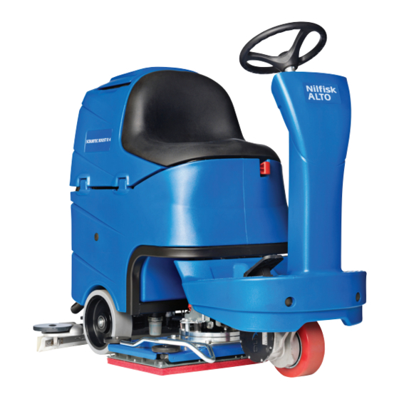
General Information Machine General Description The SCRUBTEC R 466 is a “Ride-on” industrial machine designed to wash and dry floors in one pass. The machine is powered by on-board batteries, models can be equipped with Chemical Mixing System (optional). The machine features variable floor pressure disc, cylindrical brushes or BOOST vibration system , controlled ®... -
Page 6: Conventions
General Information Service Manual – SCRUBTEC R466 ... FOCUS II Micro Rider Conventions Forward, backward, front, rear, left or right are intended with reference to the operator’s position, that is to say in driving position Service and Spare Parts Service and repairs must be performed only by authorised personnel or Nilfisk Service Centers. The authorised personnel is trained directly at the manufacturer's premises and has original spare parts and accessories Contact Nilfisk Retailer indicated below for service or to order spare parts and accessories, specifying the ma- chine model and serial number... -
Page 7: Safety
General Information Service Manual – SCRUBTEC R466 ... FOCUS II Micro Rider Safety The following symbols indicate potentially dangerous situations Always read this information carefully and take all necessary precautions to safeguard people and property Symbols Danger! It indicates a dangerous situation with risk of death for the operator. Warning! It indicates a potential risk of injury for people or damage to objects. - Page 8 General Information Service Manual – SCRUBTEC R466 ... FOCUS II Micro Rider Caution! Make sure to follow the safety precautions to avoid situations that may lead to serious injuries, damages to materials or equipments. − Carefully read all the instructions before performing any maintenance/repair procedure. −...
- Page 9 General Information Service Manual – SCRUBTEC R466 ... FOCUS II Micro Rider − The machine working temperature must be between 0 °C and +40 °C − The machine storage temperature must be between 0 °C and +40 °C − The humidity must be between 30% and 95% −...
-
Page 10: Machine Lifting
General Information Service Manual – SCRUBTEC R466 ... FOCUS II Micro Rider Machine Lifting Warning! Do not work under the lifted machine without supporting it with safety stands. Machine Transportation Warning! Before transporting the machine, make sure that: All covers are closed. The ignition key is removed. -
Page 11: Machine Nomenclature (Know Your Machine)
General Information Service Manual – SCRUBTEC R466 ... FOCUS II Micro Rider Machine Nomenclature (know your machine) Squeegee hook Bumper wheel Seat BOOST® vibration deck Battery connector Emergency push-button Steering wheel Steering wheel Recovery height control lever tank cover Control panel Dumping recovery tank assembly Ignition key... - Page 12 General Information Service Manual – SCRUBTEC R466 ... FOCUS II Micro Rider Machine Nomenclature (continued) Detergent tank Battery charger cable Electronic component compartment cover Lifted tank assembly and driver's seat Vacuum grid with Tank assembly stand automatic shut-off float Vacuum system motor filter Container with Vacuum system motor debris collection grid...
-
Page 13: Control Panel
General Information Service Manual – SCRUBTEC R466 ... FOCUS II Micro Rider Control Panel Solution flow decrease push button Solution flow increase push button Solution flow indicator Battery lights Hour counter and solution level display Anti-skid control activation led indicator Speed indicators led Speed adjustment push buttons Scrub On/Off... -
Page 14: Service And Diagnostic Equipment
General Information Service Manual – SCRUBTEC R466 ... FOCUS II Micro Rider Service and Diagnostic Equipment Besides a complete set of standard meters, the following instruments are necessary to perform fast checks and repairs on Nilfisk-Advance machines: • Laptop computer charged with the current version of EzParts, Adobe Reader and (if possible) Internet connection •... -
Page 15: Technical Data
General Information Service Manual – SCRUBTEC R466 ... FOCUS II Micro Rider Technical Data General technical data SCRUBTEC SCRUBTEC SCRUBTEC SCRUBTEC R 466 R 471 R 471C BOOST ® Description FOCUS II Micro FOCUS II Micro Rider Rider 28 BOOST Cleaning width 26 in (660 mm) 28 in (710 mm) - Page 16 General Information Service Manual – SCRUBTEC R466 ... FOCUS II Micro Rider Technical Data (continued) Technical data for machines with brush/pad-holder deck SCRUBTEC R 466 SCRUBTEC R 471 Description FOCUS II Micro Rider Brush/pad diameter 13 in (330 mm) 14 in (355 mm) Weight without batteries and with empty tanks 385.8 lb (175 kg)
-
Page 17: Dimensions
General Information Service Manual – SCRUBTEC R466 ... FOCUS II Micro Rider Dimensions SCRUBTEC R 466 - FOCUS II Micro Rider 26D 1360 mm (53.5 in) 890 mm (35 in) P100678 SCRUBTEC R 471 1360 mm (53.5 in) 890 mm (35 in) - Page 18 General Information Service Manual – SCRUBTEC R466 ... FOCUS II Micro Rider Dimensions (continued) SCRUBTEC R 471C 1360 mm (53.5 in) 890 mm (35 in) P100680 SCRUBTEC BOOST R4 - FOCUS II Micro Rider 18 BOOST ® ® 1360 mm (53.5 in) 890 mm (35 in) P100681...
-
Page 19: Maintenance
General Information Service Manual – SCRUBTEC R466 ... FOCUS II Micro Rider Maintenance The lifespan of the machine and its maximum operating safety are ensured by correct and regular mainte- nance Warning! Read carefully the instructions in the Safety chapter before performing any maintenance procedure. -
Page 20: Chassis System
Service Manual – SCRUBTEC R466 ... FOCUS II Micro Rider Chassis System Chassis System Frame (main parts) Steering assembly plate holder Tanks and driver's seat holder Rear wheels on fixed axle Front P100682... -
Page 21: Control System
Service Manual – SCRUBTEC R466 ... FOCUS II Micro Rider Control System Control System Functional Description The architecture of the electronic system controlling the electrical machine utilities consists of a function electronic board (EB1), and a display electronic board (EB2) which is connected to the dashboard (EB3) - the main user interface The function electronic board (EB1) manages all the utilities It drives directly the following accessories:... -
Page 22: Component Location
Service Manual – SCRUBTEC R466 ... FOCUS II Micro Rider Control System Component Location • Function electronic board (EB1) • Display electronic board (EB2) • Dashboard (EB3) Function electronic board (EB1) P100684 Display electronic board (EB2) Dashboard (EB3) P100685... -
Page 23: Function Electronic Board Alarm Codes
Service Manual – SCRUBTEC R466 ... FOCUS II Micro Rider Control System Function Electronic Board Alarm Codes The function electronic board indicates a series of alarms in case of malfunction of one or more systems, and in case of abnormal conditions detected in the input signals The alarms are shown on the display (71) (except “F6”) by 2 signs following each other: “AL”... - Page 24 Service Manual – SCRUBTEC R466 ... FOCUS II Micro Rider Control System General alarms Alarm on the function electronic board - YELLOW LED + RED LED FLASHING Alarm No. of Code flashes Meaning Condition Effect Troubleshooting action on the on the display board Blown F2 fuse.
- Page 25 Service Manual – SCRUBTEC R466 ... FOCUS II Micro Rider Control System Function Electronic Board Alarm Codes (continued) P100686 P100689 Function electronic board alarms Alarm on the function electronic board - RED LED FLASHING Alarm No. of Code flashes Meaning Condition Effect Troubleshooting action...
- Page 26 Service Manual – SCRUBTEC R466 ... FOCUS II Micro Rider Control System Function Electronic Board Alarm Codes (continued) P100686 P100690 Drive system alarms Alarm on the function electronic board - YELLOW LED FLASHING Alarm No. of Code flashes Meaning Condition Troubleshooting action on the on the...
- Page 27 Service Manual – SCRUBTEC R466 ... FOCUS II Micro Rider Control System Function Electronic Board Alarm Codes (continued) Other alarm indications on the display Alarm Code on the Meaning Condition display “---” Water level signal missing or not as specified. Pressure switch module output higher than 4.0 Volt.
- Page 28 Service Manual – SCRUBTEC R466 ... FOCUS II Micro Rider Control System Black-box: Record of Alarms, Battery Management Parameters (see page 32 - 33), Partial Hour Counter (continued) Example 1: Last stored alarm: alarm G8 occurred when the machine working hours were 24h and 19m, next to last stored alarm: alarm F4 occurred when the machine working hours were 22h and 5m PROGRAMMER PROGRAMMER...
-
Page 29: Display Of Current Values Of Significant Variables, Hour Counters And Stored Alarms
Service Manual – SCRUBTEC R466 ... FOCUS II Micro Rider Control System Display of Current Values of Significant Variables, Hour Counters and Stored Alarms Turn the ignition switch to “0” Open the electrical component compartment Connect the ITALSEA programmer, NILFISK P/N 9097297000 to the function electronic board connector J9 (A). - Page 30 Service Manual – SCRUBTEC R466 ... FOCUS II Micro Rider Control System Display of Current Values of Significant Variables, Hour Counters and Stored Alarms (continued) Variable description Value meaning Software Release Software version loaded on the electronic board Supply Voltage Battery voltage (V) Ref.
-
Page 31: Display And Change Of Parameters Which Can Be Set By The Technician
Service Manual – SCRUBTEC R466 ... FOCUS II Micro Rider Control System Display and Change of Parameters Which can be Set by the Technician The stored value of each parameter shown in the following table could be modified by the Service Operator from its Default value to another in the range defined from “Min. -
Page 32: Function Electronic Board Parameters
Service Manual – SCRUBTEC R466 ... FOCUS II Micro Rider Control System Function Electronic Board Parameters Parameters which can be set through programming port J9 Min. Default Max. Code Description Meaning values * values values It is the voltage supplied to the vacuum motor when Vacuum system partial supply the SILENCE MODE is active: it could be reduced VRID... - Page 33 Service Manual – SCRUBTEC R466 ... FOCUS II Micro Rider Control System Parameters which can be set through programming port J9 Default Min. Max. Code Description Meaning values values * values It is the max istantaneous current that is possible to supply to the drive motorwheel.
-
Page 34: Removal And Installation
Service Manual – SCRUBTEC R466 ... FOCUS II Micro Rider Control System Removal and Installation Display Electronic Board and Dashboard Electronic Board Replacement Display Electronic Board Disassembly Drive the machine on a level floor. Turn the ignition key to “0” and disconnect the batteries Remove the steering wheel height control lever (A) Lift the cover (B) and remove the seeger (C), then remove the steering wheel assembly (D). - Page 35 Service Manual – SCRUBTEC R466 ... FOCUS II Micro Rider Control System Display Electronic Board and Dashboard Electronic Board Replacement (continued) Dashboard Electronic Board Disassembly Perform steps 1 to 7 of the display electronic board disassembly 10 Remove the ignition key (L) 11 Remove the bush (M) 12 Carefully lift and remove the dashboard electronic board (N) from the plate (F) Assembly...
- Page 36 Service Manual – SCRUBTEC R466 ... FOCUS II Micro Rider Control System Function Electronic Board Lay-Out and Disassembly/Assembly Disassembly Drive the machine on a level floor. Turn the ignition key to “0” and disconnect the batteries Lift the recovery tank assembly Remove the 6 screws and remove the electronic component compartment cover Remove the 2 mounting screws of the function electronic board assembly and carefully remove it from the housing...
- Page 37 Service Manual – SCRUBTEC R466 ... FOCUS II Micro Rider Control System Function Electronic Board Lay-Out and Disassembly/Assembly (continued) ◦ (F) Electrical component wiring harness connection (J1). ◦ (G) Foot board wiring harness connection (J3). ◦ (H) Frame wiring harness connection (J2). ◦...
-
Page 38: Specifications
Service Manual – SCRUBTEC R466 ... FOCUS II Micro Rider Control System Specifications Connectors on the function electronic board Power connections (male RADSOK terminals Ø6mm (AMPHENOL P/N N01 060 0001 1 or equivalent)) Electronic board Ref. Description V ref. I max. Connected to in/out Electronic board power supply +... - Page 39 Service Manual – SCRUBTEC R466 ... FOCUS II Micro Rider Control System Connectors (continued) J1: MOLEX MINIFIT type, 12-ways vertical Electronic board Description V ref. I max. Connected to in/out Brush electromagnetic switch power <1A supply + Brush electromagnetic switch power <1A supply - Brush fuse voltage drop reading +...
- Page 40 Service Manual – SCRUBTEC R466 ... FOCUS II Micro Rider Control System Auxiliary power supply - <1A Connectors (continued) J3: MOLEX MINIFIT type, 10-ways vertical Electronic board Description V ref. I max. Connected to in/out Dashboard power supply + <1A EB2.1 Dashboard serial + in/out...
- Page 41 Service Manual – SCRUBTEC R466 ... FOCUS II Micro Rider Control System Connectors (continued) J5: MOLEX MINIFIT type, 2-ways vertical Electronic board Description V ref. I max. Connected to in/out Driving wheel brake power supply + Driving wheel brake power supply - J6: TYCO MODU1 type, 6-ways vertical Electronic board Description...
- Page 42 Service Manual – SCRUBTEC R466 ... FOCUS II Micro Rider Control System Connectors (continued) J7: PRESSURE SWITCH connector, Berger type, 3+3-ways vertical ( ) Pressure switch power supply + <1A Press.A1 Pressure switch power supply - <1A Press.A2 Press.A3 Press.B1 Pressure switch signal + 0-5V <1A...
-
Page 43: Electrical System
Service Manual – SCRUBTEC R466 ... FOCUS II Micro Rider Electrical System Electrical System Functional Description The batteries (two 12V or four 6V) are connected in series by bridge cables The battery charger (CH) is connected to the machine by two connectors (C) (power connection to the batteries) and C3 (3-way signal connection) The grey cables (terminals 1 and 2 of connector C3) are short-circuited in battery charger CH when it is not connected to the electrical mains. -
Page 44: Component Location
Service Manual – SCRUBTEC R466 ... FOCUS II Micro Rider Electrical System Component Location • Batteries (BAT) • Battery connections • Battery charger (CH) • Electrical panel • Battery connector (C1) • Function electronic board (EB1) Battery charger (CH) Batteries (BAT) Battery connector (C1) Battery connections... -
Page 45: Maintenance
Service Manual – SCRUBTEC R466 ... FOCUS II Micro Rider Electrical System Maintenance Charge condition display TRANSITION THRESHOLD (VOLT) INDICATION CONSEQUENCE GREEN LED: fixed - YELLOW LED: fixed 22 V 22.2 V YELLOW LED: fixed - RED LED: flashing 20.4 V 21.6 V Brushes OFF Safety threshold... -
Page 46: Troubleshooting
Service Manual – SCRUBTEC R466 ... FOCUS II Micro Rider Electrical System Troubleshooting See the other chapters related to the use of the electrical system Trouble Possible Causes Remedy The machine is not working The batteries (BAT) are discharged or its connections are Charge the batteries or clean the not efficient connections... -
Page 47: General Wiring Diagram
Service Manual – SCRUBTEC R466 ... FOCUS II Micro Rider Electrical System General Wiring Diagram Battery connector (C1+) Electromagnetic brake (BRK) Drive Vacuum system system Brush deck motor (M3) motor (M2) connector (C4+) Squeegee actuator motor (M6) Brush 24 V battery motor (M1.1,2) Flashing box (BAT) -
Page 48: Specifications
Service Manual – SCRUBTEC R466 ... FOCUS II Micro Rider Electrical System Specifications Battery compartment size (length x width x height) 14.9 x 21.2 x 11.8 in (380 x 540 x 300 mm) 4 6 V batteries, 180 Ah C5 (WET) Battery type 4 6 V batteries, 180 Ah C5 (GEL/AGM) Standard batteries autonomy (capacity) -
Page 49: Recovery System
Service Manual – SCRUBTEC R466 ... FOCUS II Micro Rider Recovery System Recovery System Functional Description The water recovery system removes the dirty water from the floor and pipes it to a recovery tank. When the machine is running, the dirty water on the floor is collected by the squeegee blades and collected through the slots in the same, piped through the vacuum hose and into the tank by the airflow created by Vacuum system motor (M2). -
Page 50: Component Location
Service Manual – SCRUBTEC R466 ... FOCUS II Micro Rider Recovery System Component Location • Recovery tank • Squeegee vacuum hose • Recovery tank cover • Recovery water drain hose • Gasket cover • Vacuum system wiring harness connection • Container with debris collection grid •... -
Page 51: Maintenance And Adjustments
Service Manual – SCRUBTEC R466 ... FOCUS II Micro Rider Recovery System Maintenance and Adjustments Recovery Tank Cleaning Drive the machine to the appointed disposal area Turn the ignition key to “0” Open the recovery tank cover Clean and wash the cover and the recovery tank with clean water Empty the recovery tank with the drain hose Clean the vacuum grid, release the fasteners (A), open the grid (B) and recover the float (C) then clean carefully and reinstall... -
Page 52: Troubleshooting
Service Manual – SCRUBTEC R466 ... FOCUS II Micro Rider Recovery System Troubleshooting Trouble Possible Causes Remedy The vacuum system motor does not turn The wiring harness between function electronic board Repair (EB1) and vacuum system motor (M2) is damaged The vacuum system motor carbon brushes are worn Replace The dashboard instrument electronic board (EB3) is... -
Page 53: Removal And Installation
Service Manual – SCRUBTEC R466 ... FOCUS II Micro Rider Recovery System Removal and Installation Vacuum system motor electrical input check Warning! This procedure must be performed by qualified personnel only. Install an Amp clamp (A) on one cable (B) of the batteries Turn the ignition key to “I”... - Page 54 Service Manual – SCRUBTEC R466 ... FOCUS II Micro Rider Recovery System Vacuum System Motor Carbon Brush Check/Replacement Remove the vacuum system motor (see the procedure in the following paragraph) At the workbench, remove the screws and the cover (A) from the vacuum system motor (B). Remove the screws (C) Disconnect the electrical connections (D) Remove the carbon brushes (E)
- Page 55 Service Manual – SCRUBTEC R466 ... FOCUS II Micro Rider Recovery System Vacuum System Motor Disassembly/Assembly Disassembly If there is recovery water in the tank, drain it. Turn the ignition key to “0” and disconnect the batteries Lift the recovery tank assembly Remove the screws (A) and recover the washers Remove the motor cover (B) Remove the filter (C) and the gasket (D).
-
Page 56: Specifications
Service Manual – SCRUBTEC R466 ... FOCUS II Micro Rider Recovery System Specifications SCRUBTEC SCRUBTEC SCRUBTEC SCRUBTEC R 466 R 471 R 471C BOOST ® Description FOCUS II Micro FOCUS II Micro Rider Rider 28 BOOST Recovery tank capacity 21 US gal (80 L) 0.56 hp (420 W) 20.8A VDC 24V Vacuum system motor technical data... -
Page 57: Scrub System, Cylindrical
Service Manual – SCRUBTEC R466 ... FOCUS II Micro Rider Scrub System, Cylindrical Scrub System, Cylindrical Functional Description The cylindrical brush system can be started by the operator The cylindrical brushes turn in opposite directions towards the centre of the deck The rotating brush system cleans the surface of the floor. -
Page 58: Wiring Diagram
Service Manual – SCRUBTEC R466 ... FOCUS II Micro Rider Scrub System, Cylindrical Wiring Diagram Power supply (B+) Function electronic Brush motors board (EB1) (M1.1 - M1.2) Brush motor J1.2 electromagnetic switch Negative ref. J1.1 (ES1) Positive ref. Shunt + Brush deck fuse (F1) Shunt -... -
Page 59: Component Location
Service Manual – SCRUBTEC R466 ... FOCUS II Micro Rider Scrub System, Cylindrical Component Location • Cylindrical brush deck • Roller belt tensioner • Debris container • Driving belt • Side skirts • Brush pulley • Crankcase belt protection • Support brush •... - Page 60 Service Manual – SCRUBTEC R466 ... FOCUS II Micro Rider Scrub System, Cylindrical Component Location (continued) • Brush deck lifting/lowering actuator • Brush deck fuse (F1) • Brush motor electromagnetic switch (ES1) • Actuator system wiring harness connection • Brush motor (M1 1 - M1 2) •...
-
Page 61: Maintenance And Adjustments
Service Manual – SCRUBTEC R466 ... FOCUS II Micro Rider Scrub System, Cylindrical Maintenance and Adjustments Cylindrical brush installation/removal Insert the ignition key and turn it to “I” Warning! Before pressing the scrub On/Off push button , always check that, between the deck and the machine there is no foreign material which may prevent the deck from lifting. -
Page 62: Side Skirt Check And Replacement
Service Manual – SCRUBTEC R466 ... FOCUS II Micro Rider Scrub System, Cylindrical Side skirt check and replacement Check Assembly and height adjustment Drive the machine on a level floor. Assemble the blades (G) and skirt assembly (B) Turn the ignition key to “0” in the reverse order of disassembly On both sides of the machine, loosen the knobs 10 Start the machine and lower the cylindrical... -
Page 63: Troubleshooting
Service Manual – SCRUBTEC R466 ... FOCUS II Micro Rider Scrub System, Cylindrical Troubleshooting Open circuit • The Brush deck fuse (F1) determines an open in the supply circuit of the brush deck motors This system allows to prevents the wiring from being damaged under overload conditions •... -
Page 64: Removal And Installation
Service Manual – SCRUBTEC R466 ... FOCUS II Micro Rider Scrub System, Cylindrical Removal and Installation Removing and Installing the Brush Deck washer Disassembly Drive the machine on a level floor or on a Turn the ignition key to “I”, lift the deck holder hoisting system to facilitate the disassembly (E) by pressing the scrub On/Off push button procedures... - Page 65 Service Manual – SCRUBTEC R466 ... FOCUS II Micro Rider Scrub System, Cylindrical Brush motor electrical input check Warning! This procedure must be performed by qualified personnel only. Drive the machine on a level floor. Remove the brushes Place two wooden shims (E) under the side areas of the cylindrical brush deck (C) as shown in the figure. Wooden shim thickness must be 25 mm Use a jumper wire to disable the driver's seat microswitch Disconnect the driving wheel connector to disable the drive system...
- Page 66 Service Manual – SCRUBTEC R466 ... FOCUS II Micro Rider Scrub System, Cylindrical Brush Motor Electrical Input Check (continued) 12 If the electrical input is higher, perform the following procedures to detect and correct the abnormal input: Note: If the electrical input is higher than the maximum allowed value, the 3 battery warning lights flash simultaneously.
- Page 67 Service Manual – SCRUBTEC R466 ... FOCUS II Micro Rider Scrub System, Cylindrical Brush Motor Carbon Brush Check/Replacement Check Remove the brush motor At the workbench, remove dust and debris from the motor, especially in the area of the protection clamp Remove the protection clamp (A) For each carbon brush, move the protection (B) and remove the screws (C).
- Page 68 Service Manual – SCRUBTEC R466 ... FOCUS II Micro Rider Scrub System, Cylindrical Brush Motor Disassembly/Assembly Disassembly Remove the cylindrical brush deck (see the procedure in “Cylindrical Brush Deck Disassembly/ Assembly” paragraph) On the machine side where the brush motor has to be removed, unscrew the knobs and remove the side skirt assembly Remove the screws (A) and remove the case (B) P100723...
- Page 69 Service Manual – SCRUBTEC R466 ... FOCUS II Micro Rider Scrub System, Cylindrical Brush Motor Disassembly/Assembly (continued) Remove the guard (C) Loosen the nut (D) and move the pulley (E) to loosen the belt (F) Remove the belt (F) Remove the screws (G) Remove the motor (H).
- Page 70 Service Manual – SCRUBTEC R466 ... FOCUS II Micro Rider Scrub System, Cylindrical Check/replacement/adjustment of driving belts between motors and cylindrical brushes Check Drive the machine on a level floor. Lower the brush deck by pressing the scrub On/Off push button Turn the ignition key to “0”...
- Page 71 Service Manual – SCRUBTEC R466 ... FOCUS II Micro Rider Scrub System, Cylindrical Check/replacement/adjustment of driving belts between motors and cylindrical brushes (continued) Replacement If the belt (C) is to be replaced, remove the guard (D), loosen the nut (E) and move the pulley (F) to loosen the belt Remove or replace the driving belt 10 Stretch the driving belt (according to the following procedure)
- Page 72 Service Manual – SCRUBTEC R466 ... FOCUS II Micro Rider Scrub System, Cylindrical Brush Deck Lifting/Lowering Actuator Disassembly/Assembly Disassembly Lower the brush deck Remove the cylindrical brush deck (see the procedure in “Cylindrical Brush Deck Disassembly/ Assembly” paragraph) Turn the ignition key to “0” and disconnect the batteries Disconnect the actuator connector (see the function electronic board) Remove the screw (A) and recover nuts, bushings and washers.
-
Page 73: Specifications
Service Manual – SCRUBTEC R466 ... FOCUS II Micro Rider Scrub System, Cylindrical Specifications Description SCRUBTEC R 471C Cleaning width 28 in (710 mm) Cylindrical brush size (diameter x length) 5.7 x 27.2 in (145 x 690 mm) Deck right/left offset 3.5 / 3.5 in (90 / 90 mm) Cylindrical brush deck distance from the floor (when lifted) 0.8 in (22 mm) -
Page 74: Scrub System, Disc
Service Manual – SCRUBTEC R466 ... FOCUS II Micro Rider Scrub System, Disc Scrub System, Disc Functional Description The disc brush system can be started by the operator The disc brushes turn in opposite directions towards the centre of the header The rotating brush system cleans the surface of the floor. -
Page 75: Wiring Diagram
Service Manual – SCRUBTEC R466 ... FOCUS II Micro Rider Scrub System, Disc Wiring Diagram Power supply (B+) Function electronic Brush motors board (EB1) (M1.1 - M1.2) Brush motor J1.2 electromagnetic switch Negative ref. J1.1 (ES1) Positive ref. Shunt + Brush deck fuse (F1) Shunt -... -
Page 76: Component Location
Service Manual – SCRUBTEC R466 ... FOCUS II Micro Rider Scrub System, Disc Component Location • Disc brush deck • Gas spring for extra pressure • Brush gearmotor (M1, M2) • Brush electromagnetic switch (ES1) • Drive hub • “Magic deck” system •... -
Page 77: Component Location (Continued)
Service Manual – SCRUBTEC R466 ... FOCUS II Micro Rider Scrub System, Disc Component Location (continued) • Brush deck fuse (F1) • Actuator system wiring harness connection • Function electronic board (EB1) Function electronic board (EB1) Actuator system wiring harness con- nection Brush deck fuse (F1) (into fuse holder) -
Page 78: Maintenance And Adjustments
Service Manual – SCRUBTEC R466 ... FOCUS II Micro Rider Scrub System, Disc Maintenance and Adjustments Brush/pad-holder installation/removal Insert the ignition key and turn it to “I” Warning! Before pressing the scrub On/Off push button , always check that, between the deck and the machine there is no foreign material which may prevent the deck from lifting. -
Page 79: Troubleshooting
Service Manual – SCRUBTEC R466 ... FOCUS II Micro Rider Scrub System, Disc Troubleshooting Open circuit • The fuse (F1) determines an open in the supply circuit of the brush deck motors This system allows to prevent the circuits from being damaged under overload conditions •... -
Page 80: Removal And Installation
Service Manual – SCRUBTEC R466 ... FOCUS II Micro Rider Scrub System, Disc Removal and Installation Removing and Installing the Brush Deck Disconnect the solution hose union (B) Disassembly Drive the machine on a level floor or on a Remove the screw (C) and recover the nut hoisting system to facilitate the disassembly Remove the safety pins (D) procedures... - Page 81 Service Manual – SCRUBTEC R466 ... FOCUS II Micro Rider Scrub System, Disc Brush motor electrical input check Warning! This procedure must be performed by qualified personnel only. Drive the machine on a level floor. Remove the brushes Place two wooden shims (A) under the side areas of the deck (B) as shown in the figure. Wooden shim thickness must be 25 mm Warning! Keep the wooden shims at an appropriate distance from the brush hubs.
- Page 82 Service Manual – SCRUBTEC R466 ... FOCUS II Micro Rider Scrub System, Disc Brush Motor Electrical Input Check (continued) 12 If the electrical input is higher, perform the following procedures to detect and correct the abnormal input: Note: If the electrical input is higher than the maximum allowed value, the 3 battery warning lights flash simultaneously.
- Page 83 Service Manual – SCRUBTEC R466 ... FOCUS II Micro Rider Scrub System, Disc Brush Motor Carbon Brush Check/Replacement Check Remove the brush/pad-holder deck. Remove dust and dirt from the motor carbon brush support area (A) Disengage the fasteners (B) and (C), then remove the four carbon brush supports (A). If necessary, disconnect the electrical connections (D) Check the carbon brushes (E) for wear Replace the carbon brushes when: ◦...
- Page 84 Service Manual – SCRUBTEC R466 ... FOCUS II Micro Rider Scrub System, Disc Brush Motor Disassembly/Assembly Disassembly Assembly Remove the brush/pad-holder deck. Assemble the components in the reverse order of At the workbench, remove the screw (A) from disassembly the reduction unit which has to be disassembled Remove the hub assembly (B) with a puller Remove the screws (C) Remove the gearmotor (D)
- Page 85 Service Manual – SCRUBTEC R466 ... FOCUS II Micro Rider Scrub System, Disc Brush Deck Lifting/Lowering Actuator Disassembly/Assembly Disassembly Lower the brush deck Remove the deck Turn the ignition key to “0” and disconnect the batteries Disconnect the actuator connector (see the function electronic board) Remove the screw (A) and recover nuts, bushings and washers.
- Page 86 Service Manual – SCRUBTEC R466 ... FOCUS II Micro Rider Scrub System, Disc Brush Deck Adjuster Spring Disassembly/Assembly Disassembly Drive the machine on a level floor. Remove the brush deck Turn the ignition key to “0” and disconnect the batteries Remove the front fairing (see the procedure in “Front Fairing Disassembly/Assembly”...
- Page 87 Service Manual – SCRUBTEC R466 ... FOCUS II Micro Rider Scrub System, Disc Brush Deck Drive Guide Disassembly/Assembly Disassembly Drive the machine on a level floor. Remove the brush/pad-holder deck and leave the deck holder assembly lifted. Turn the ignition key to “0” and disconnect the batteries Turn the steering wheel to accommodate the position of the drive guide (A) to be removed Under the machine, remove the screws (B) and the drive guide (A).
-
Page 88: Specifications
Service Manual – SCRUBTEC R466 ... FOCUS II Micro Rider Scrub System, Disc Specifications SCRUBTEC R 466 SCRUBTEC R 471 Description FOCUS II Micro Rider Cleaning width 26 in (660 mm) 28 in (710 mm) Brush/pad diameter 13 in (330 mm) 14 in (355 mm) 0 ÷... -
Page 89: Scrub System, Boost
Service Manual – SCRUBTEC R466 ... FOCUS II Micro Rider Scrub System, BOOST ® Scrub System, BOOST ® Functional Description The BOOST system can be started by the operator ® The main part of the system is the vibrating deck, the motor with an eccentric transmits the vibration needed to cause the scrub of the pad on the floor to be cleaned. -
Page 90: Wiring Diagram
Service Manual – SCRUBTEC R466 ... FOCUS II Micro Rider Scrub System, BOOST ® Wiring Diagram Power supply (B+) Function electronic BOOST motor ® board (EB1) (M1) Brush motor J1.2 electromagnetic switch Negative ref. J1.1 (ES1) Positive ref. Shunt + Brush deck fuse (F1) Shunt -... -
Page 91: Component Location
Service Manual – SCRUBTEC R466 ... FOCUS II Micro Rider Scrub System, BOOST ® Component Location • BOOST deck • Brush deck lifting/lowering actuator (M5) ® • Flex plate • Gas spring for extra pressure • Pad • Brush electromagnetic switch (ES1) •... -
Page 92: Component Location (Continued)
Service Manual – SCRUBTEC R466 ... FOCUS II Micro Rider Scrub System, BOOST ® Component Location (continued) • BOOST deck fuse (F1) ® • Actuator system wiring harness connection • Function electronic board (EB1) Function electronic board (EB1) Actuator system wiring harness con- nection BOOST... -
Page 93: Maintenance And Adjustments
Service Manual – SCRUBTEC R466 ... FOCUS II Micro Rider Scrub System, BOOST ® Maintenance and Adjustments Brush/pad-holder installation/removal Insert the ignition key and turn it to “I” Warning! Before pressing the scrub On/Off push button , always check that, between the deck and the machine there is no foreign material which may prevent the deck from lifting. -
Page 94: Troubleshooting
Service Manual – SCRUBTEC R466 ... FOCUS II Micro Rider Scrub System, BOOST ® Troubleshooting Open circuit • The fuse (F1) determines an open in the supply circuit of the BOOST deck motors This system allows to ® prevent the circuits from being damaged under overload conditions •... -
Page 95: Removal And Installation
Service Manual – SCRUBTEC R466 ... FOCUS II Micro Rider Scrub System, BOOST ® Removal and Installation Removing and Installing the Brush Deck 12 Remove the screws (G), the nuts (H) and recover Disassembly Drive the machine on a level floor or on a the spacers hoisting system to facilitate the disassembly 13 Disassemble the BOOST®... - Page 96 Service Manual – SCRUBTEC R466 ... FOCUS II Micro Rider Scrub System, BOOST ® BOOST motor electrical input check ® Warning! This procedure must be performed by qualified personnel only. 15 Drive the machine on a level floor. 16 Use a jumper wire to disable the driver’s seat microswitch. 17 Disconnect the driving wheel connector to disable the drive system 18 Lower the BOOST®...
- Page 97 Service Manual – SCRUBTEC R466 ... FOCUS II Micro Rider Scrub System, BOOST ® BOOST Motor Carbon Brush Check/Replacement ® Remove the BOOST® deck (see the procedure in the relevant paragraph) Place the deck on a workbench Note: The motor cannot be disassembled with BOOST® deck installed on the machine. Remove the connector holder Remove the wire mounting nut and the rubber gasket Remove the wire...
- Page 98 Service Manual – SCRUBTEC R466 ... FOCUS II Micro Rider Scrub System, BOOST ® BOOST Motor Carbon Brush Check/Replacement (continues) ® Remove the top cover P100474 Replace the carbon brushes ◦ Before disassembly, note the spring position when the carbon brush is being pushed back. ◦...
- Page 99 Service Manual – SCRUBTEC R466 ... FOCUS II Micro Rider Scrub System, BOOST ® BOOST Motor Carbon Brush Check/Replacement (continues) ® P100476 ◦ Install the other three carbon brushes Install the wave washer Install the top cover ◦ Install it far enough so that the carbon brushes make contact with the collector when the temporary support wires are removed Then remove the temporary wires Collector Carbon brush...
- Page 100 Service Manual – SCRUBTEC R466 ... FOCUS II Micro Rider Scrub System, BOOST ® BOOST deck Motor Disassembly/Assembly ® Disassembly Assembly Remove the BOOST deck from the machine Assemble the components in the reverse order of ® disassembly, and note the following: At the workbench, remove the screw (A), recover ◦...
- Page 101 Service Manual – SCRUBTEC R466 ... FOCUS II Micro Rider Scrub System, BOOST ® BOOST deck vibration-dampers disassembly/replacement ® remove the BOOST deck from the machine Assemble the new vibration-dampers in the ® reverse order of disassembly, and note the At the workbench, remove the screw (A), recover following: the washer and remove the locking eccentric disc...
- Page 102 Service Manual – SCRUBTEC R466 ... FOCUS II Micro Rider Scrub System, BOOST ® BOOST deck vibration-dampers disassembly/replacement (continues) ® Remove the screws (K) and recover washers and spacers (L) Remove the nuts (M) and lift the stay assembly (N) 10 Remove the vibration-dampers (O) by unscrewing them from the ring (P) 11 Assemble the new vibration-dampers in the reverse order of disassembly, and note the following: ◦...
- Page 103 Service Manual – SCRUBTEC R466 ... FOCUS II Micro Rider Scrub System, BOOST ® BOOST Deck Lifting/Lowering Actuator Disassembly/Assembly ® Disassembly Lower the BOOST® deck Remove the BOOST® deck Turn the ignition key to “0” and disconnect the batteries Disconnect the actuator connector (see the function electronic board) Remove the screw (A) and recover nuts, bushings and washers.
- Page 104 Service Manual – SCRUBTEC R466 ... FOCUS II Micro Rider Scrub System, BOOST ® BOOST Deck Adjuster Spring Disassembly/Assembly ® Disassembly Drive the machine on a level floor. Remove the BOOST® deck Turn the ignition key to “0” and disconnect the batteries Remove the front fairing (see the procedure in “Front Fairing Disassembly/Assembly”...
- Page 105 Service Manual – SCRUBTEC R466 ... FOCUS II Micro Rider Scrub System, BOOST ® BOOST Deck Drive Guide Disassembly/Assembly ® Disassembly Drive the machine on a level floor. Remove the BOOST® deck and leave the deck holder assembly lifted Turn the ignition key to “0” and disconnect the batteries Turn the steering wheel to accommodate the position of the drive guide (A) to be removed Under the machine, remove the screws (B) and the drive guide (A).
-
Page 106: Specifications
Service Manual – SCRUBTEC R466 ... FOCUS II Micro Rider Scrub System, BOOST ® Specifications SCRUBTEC BOOST ® Description FOCUS II Micro Rider 28 BOOST Pad size 28 x 14 in (711 x 355.6 mm) Weight without batteries and with empty tanks 401 lb (182 kg) Maximum weight with batteries, full tanks and operator (GVW) 1,005 lb (456 kg) -
Page 107: Solution System
Service Manual – SCRUBTEC R466 ... FOCUS II Micro Rider Solution System Solution System Functional Description The solution system supplies water and detergent to the brushes when cleaning the floor. The solution tank is also the main machine body There is a manual valve on the right side of the tank to close the water sup- ply whenever maintenance must be performed on the machine. -
Page 108: Component Location
Service Manual – SCRUBTEC R466 ... FOCUS II Micro Rider Solution System Component Location • Solution/clean water tank • Chemical Mixing System detergent tank • Filling cap • Chemical Mixing System detergent pump (M4) • Solution/clean water valve • One-way valve •... -
Page 109: Maintenance And Adjustments
Service Manual – SCRUBTEC R466 ... FOCUS II Micro Rider Solution System Maintenance and Adjustments Solution/clean water tank emptying Drive the machine to the appointed disposal area Turn the ignition key to “0” Remove the adapter from its housing inside the battery compartment Install the adapter (A) on the squeegee vacuum hose (B), then fasten it to the drain valve (C). -
Page 110: Solution Filter Cleaning
Service Manual – SCRUBTEC R466 ... FOCUS II Micro Rider Solution System Solution filter cleaning Drive the machine on a level floor. Turn the ignition key to “0” Close the solution valve (A) under the machine, behind the right rear wheel. The valve (A) is closed when it is in the position (B) and it is open when it is in the position (C) Remove the transparent cup (D), recover the gasket (E), then remove the filter strainer (F) under the machine, in front of the right rear wheel. - Page 111 Service Manual – SCRUBTEC R466 ... FOCUS II Micro Rider Solution System Chemical Mixing System Draining To remove the detergent remained in the hoses and in the pump, perform the following procedure. Turn on the machine by turning the ignition key to “I” Press the detergent concentration control push button Check that the push button LED turns on Press the detergent concentration control push button...
-
Page 112: Troubleshooting
Service Manual – SCRUBTEC R466 ... FOCUS II Micro Rider Solution System Troubleshooting Trouble Possible Causes Remedy Small amount of solution or no solution The tank filter (optional) is clogged/dirty Clean the filter reaches the brush The solution filter is clogged/dirty Clean the filter The solution valve is closed/semi-closed Replace the valve... - Page 113 Service Manual – SCRUBTEC R466 ... FOCUS II Micro Rider Solution System Troubleshooting (continued) Trouble Possible Causes Remedy Small amount of Chemical Mixing System The detergent flow percentage is too low Check/change the percentage as detergent or no detergent reaches the shown in the User Manual brush The hydraulic circuit upstream of the detergent pump is...
-
Page 114: Removal And Installation
Service Manual – SCRUBTEC R466 ... FOCUS II Micro Rider Solution System Removal and Installation Solution System Solenoid Valve/Filter Disassembly/Assembly Disassembly Assembly Place the machine on a hoisting system (if Assemble the components in the reverse order of available), then lift it. Otherwise, drive the disassembly, and note the following: machine on a level floor. - Page 115 Service Manual – SCRUBTEC R466 ... FOCUS II Micro Rider Solution System Detergent Pump And One-Way Valve Disassembly/Assembly Disassembly Assembly Place the machine on a hoisting system (if 10 Assemble the components in the reverse order of available), then lift it. Otherwise, drive the disassembly, and note the following: machine on a level floor.
-
Page 116: Specifications
Service Manual – SCRUBTEC R466 ... FOCUS II Micro Rider Solution System Specifications SCRUBTEC SCRUBTEC SCRUBTEC SCRUBTEC R 466 R 471 R 471C BOOST ® Description FOCUS II Micro FOCUS II Micro Rider Rider 28 BOOST Solution/clean water tank capacity 21 US gal (80 L) Solution flow 0.26 to 0.8 US gal/min. -
Page 117: Squeegee System
Service Manual – SCRUBTEC R466 ... FOCUS II Micro Rider Squeegee System Squeegee System Functional Description The squeegee system cleans the liquid off the floor, which is then collected by the recovery system. The squeegee is mounted on castors and the weight of the system presses it down on the floor. The squeegee is held in place by two quick-fit wing nuts in the squeegee support slots. -
Page 118: Component Location
Service Manual – SCRUBTEC R466 ... FOCUS II Micro Rider Squeegee System Component Location • Squeegee • Squeegee blades • Squeegee holder • Mounting handwheels • Squeegee adjustment • Actuator (M6) • Squeegee lifting cable Actuator (M6) Squeegee lifting cable Squeegee adjust- ment Squeegee holder... -
Page 119: Maintenance And Adjustments
Service Manual – SCRUBTEC R466 ... FOCUS II Micro Rider Squeegee System Maintenance and Adjustments Squeegee cleaning Note: The squeegee must be clean and its blades must be in good conditions in order to get a good drying. Warning! It is advisable to wear protective gloves when cleaning the squeegee because there may be sharp debris. -
Page 120: Squeegee Blade Check And Replacement
Service Manual – SCRUBTEC R466 ... FOCUS II Micro Rider Squeegee System Squeegee blade check and replacement Note: The squeegee must be clean and its blades must be in good condition in order to get a good drying. Warning! It is advisable to wear protective gloves when cleaning the squeegee because there may be sharp debris. -
Page 121: Troubleshooting
Service Manual – SCRUBTEC R466 ... FOCUS II Micro Rider Squeegee System Troubleshooting Trouble Possible Causes Remedy Dirty water vacuuming is insufficient or The squeegee or the vacuum hose is clogged or Clean or repair/replace there is no vacuuming damaged The squeegee leaves lining on the floor There is debris under the blade Remove... -
Page 122: Removal And Installation
Service Manual – SCRUBTEC R466 ... FOCUS II Micro Rider Squeegee System Removal and Installation Squeegee Lifting Actuator Disassembly/Assembly Disassembly Lower the squeegee Turn the ignition key to “0” and disconnect the batteries Disengage the cable grommet (A) and remove it from the squeegee Remove the screws (B) and recover the washers Remove the screw (C) and recover the nut Disconnect the connector (D) and remove the squeegee lifting assembly (E) - Page 123 Service Manual – SCRUBTEC R466 ... FOCUS II Micro Rider Squeegee System Squeegee Lifting Cable Disassembly/Assembly Disassembly Assembly Remove the squeegee lifting assembly (see the Install the lifting cable and note the following: previous paragraph, steps 1 to 6). ◦ Apply AGIP GR 30 grease or equivalent on At the workbench, remove the screw (A) and the entire length of the cable...
-
Page 124: Specifications
Service Manual – SCRUBTEC R466 ... FOCUS II Micro Rider Squeegee System Specifications SCRUBTEC SCRUBTEC SCRUBTEC SCRUBTEC R 466 R 471 R 471C BOOST ® Description FOCUS II Micro FOCUS II Micro Rider Rider 28 BOOST Squeegee width 35 in (890 mm) 500 N Maximum load Maximum speed... -
Page 125: Steering System
Service Manual – SCRUBTEC R466 ... FOCUS II Micro Rider Steering System Steering System Functional Description The steering system connects the steering wheel to the driving wheel assembly The reduction gear pinion transmits the movement to the steering crown connected to the driving wheel as- sembly The driving wheel assembly is also equipped with the gear for “magic deck”... -
Page 126: Removal And Installation
Service Manual – SCRUBTEC R466 ... FOCUS II Micro Rider Steering System Removal and Installation Front Fairing Disassembly/Assembly Disassembly Drive the machine on a level floor with the recovery tank empty. Turn the ignition key to “0” and disconnect the batteries Unscrew the steering wheel height control lever (A) Remove the steering wheel assembly (B), disconnect the wiring harness connection. - Page 127 Service Manual – SCRUBTEC R466 ... FOCUS II Micro Rider Steering System Front Fairing Disassembly/Assembly (continued) Remove the screws (G), recover the washers, disconnect the wiring harness and then remove the drive pedal (H). Remove the caps, the screws (I) on the machine front and recover the washers. 10 Remove the caps, the screws (J) on the machine foot board and recover the washers and the nuts.
-
Page 128: Wheel System, Driving
Service Manual – SCRUBTEC R466 ... FOCUS II Micro Rider Wheel System, Driving Wheel System, Driving Functional Description The driving wheel system moves the machine forwards The operator adjusts the operating speed with the accelerator (RV1) The reverse push button are into control panel The driving wheel is connected to the steering system The electromagnetic brake is built into the drive system... -
Page 129: Wiring Diagram
Service Manual – SCRUBTEC R466 ... FOCUS II Micro Rider Wheel System, Driving Wiring Diagram Driving wheel brake power supply - Electromagnetic brake (BRK) Driving wheel brake power supply + Drive system motor - Drive system Drive system motor + motor (M3) Lamp / seat microswitch / float power supply - Return from driver’s seat microswitch... -
Page 130: Component Location
Service Manual – SCRUBTEC R466 ... FOCUS II Micro Rider Wheel System, Driving Component Location • Accelerator pedal (RV1) • Reverse switch • Speed adjustment switchers • Speed indicator LEDS • Anti-skid control LED • Driving wheel assembly • Drive system motor (M3) •... -
Page 131: Troubleshooting
Service Manual – SCRUBTEC R466 ... FOCUS II Micro Rider Wheel System, Driving Troubleshooting Trouble Possible Causes Remedy The machine does not move The battery voltage is too low Charge the battery The drive pedal potentiometer (RV1) is misadjusted or Replace the pedal broken The function electronic board (EB1) is faulty... -
Page 132: Removal And Installation
Service Manual – SCRUBTEC R466 ... FOCUS II Micro Rider Wheel System, Driving Removal and Installation Front Fairing Disassembly/Assembly Disassembly Drive the machine on a level floor with the recovery tank empty. Turn the ignition key to “0” and disconnect the batteries Unscrew the steering wheel height control lever (A) Remove the steering wheel assembly (B), disconnect the wiring harness connection. - Page 133 Service Manual – SCRUBTEC R466 ... FOCUS II Micro Rider Wheel System, Driving Front Fairing Disassembly/Assembly (continued) Remove the screws (G), recover the washers, disconnect the wiring harness and then remove the drive pedal (H). Remove the caps, the screws (I) on the machine front and recover the washers. 10 Remove the caps, the screws (J) on the machine foot board and recover the washers and the nuts.
- Page 134 Service Manual – SCRUBTEC R466 ... FOCUS II Micro Rider Wheel System, Driving Drive system motor electrical input check Warning! This procedure must be performed by qualified personnel only and with the help of an assistant. Drive the machine on a level floor. Apply proper wedges to rear wheels, so that the machine cannot move when the front wheel is lifted.
- Page 135 Service Manual – SCRUBTEC R466 ... FOCUS II Micro Rider Wheel System, Driving Drive system motor carbon brush check/replacement Check and replacement Drive the machine on a level floor. Turn the ignition key to “0” and disconnect the batteries Remove the electromagnetic brake (see the procedure in the relevant paragraph) Remove the drive system motor (see the procedure in the relevant paragraph)
- Page 136 Service Manual – SCRUBTEC R466 ... FOCUS II Micro Rider Wheel System, Driving Drive System Motor Disassembly/Assembly Disassembly Drive the machine on a level floor. Turn the ignition key to “0” and disconnect the batteries Under the driving wheel assembly, disconnect the drive system motor and electromagnetic brake connections (A) Remove the electromagnetic brake (see the procedure in the relevant paragraph) Remove the driving wheel assembly (see the procedure in the relevant paragraph)
- Page 137 Service Manual – SCRUBTEC R466 ... FOCUS II Micro Rider Wheel System, Driving Drive System Motor Disassembly/Assembly (continued) Oil seal replacement Remove the screw (F) and recover the washer 10 Carefully remove the gear (G) from the motor pin (I) 11 Remove and replace the oil seal gasket (H).
- Page 138 Service Manual – SCRUBTEC R466 ... FOCUS II Micro Rider Wheel System, Driving Driving wheel unit disassembly/assembly Warning! This procedure must be performed by qualified personnel only and with the help of an assistant. Drive the machine on a level floor. Turn the ignition key to “0”...
- Page 139 Service Manual – SCRUBTEC R466 ... FOCUS II Micro Rider Wheel System, Driving Driving wheel unit disassembly/assembly (continued) Assembly 12 Assemble the components in the reverse order of disassembly, and note the following: ◦ Tighten the screws (H) at 16 Nm. ◦...
- Page 140 Service Manual – SCRUBTEC R466 ... FOCUS II Micro Rider Wheel System, Driving Driver's Seat Safety Microswitch Replacement Disassembly Drive the machine on a level floor. Turn the ignition key to “0” and disconnect the batteries Lift the recovery tank assembly and remove the driver's seat mounting screws Disconnect the microswitch connector Lift the recovery tank cover and remove the remaining driver's seat mounting screws Remove the driver's seat, remove the wiring harness from the hole and then remove the driver's seat...
- Page 141 Service Manual – SCRUBTEC R466 ... FOCUS II Micro Rider Wheel System, Driving Electromagnetic Brake Disassembly/Assembly Disassembly Place the machine on a hoisting system (if available), then lift it. Otherwise, drive the machine on a level floor. Lower the brush deck Turn the ignition key to “0”...
-
Page 142: Specifications
Service Manual – SCRUBTEC R466 ... FOCUS II Micro Rider Wheel System, Driving Specifications SCRUBTEC SCRUBTEC SCRUBTEC SCRUBTEC R 466 R 471 R 471C BOOST ® Description FOCUS II Micro FOCUS II Micro Rider Rider 28 BOOST Rear wheel diameter 9.8 in (250 mm) Rear wheel specific pressure on the floor (*) 130 psi (0.9 N/mm...
Need help?
Do you have a question about the SCRUBTEC R 466 and is the answer not in the manual?
Questions and answers