Table of Contents
Advertisement
Quick Links
Advertisement
Table of Contents

Related Manuals for AIC SB110-CT


Summary of Contents for AIC SB110-CT
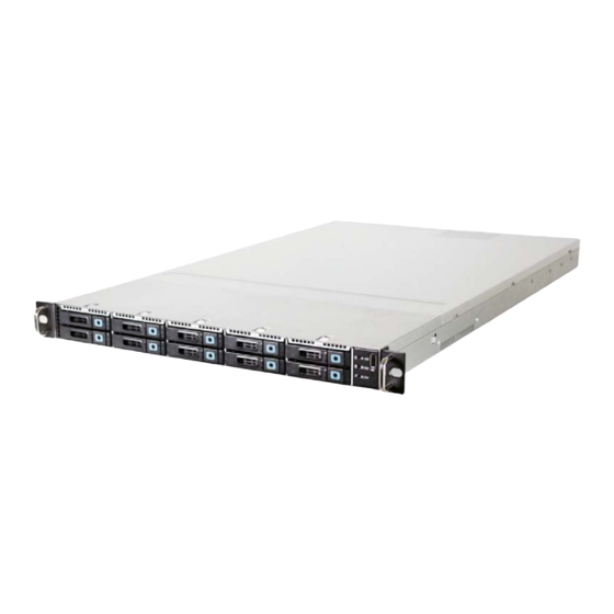
- Page 1 SB110-CT Storage Server Barebone User’s Manual Document Number : MAN-00103-A ...
-
Page 2: Table Of Contents
................5 1.1 General Information ........................5 1.2 System Specifications ......................6 1.3 Front View of SB110-CT ......................8 1.4 Rear View of SB110-CT ..................... 1.5 Top View of SB110-CT ........................9 Chapter 2 : Hardware Setup ..................10 2.1 Chassis Cover ..........................10 2.1.1 Removing the Chassis Cover...................10 ... - Page 3 Updating BMC Configuration ....................42 Chapter 6 : Technical Support ..................43 Copyright © 2011 Advanced Industrial Computer .Inc. All Rights Reserved. This document contains proprietary information about AIC products and is not to be disclosed or used except in accordance with applicable agreements. ...
-
Page 4: Safety Information
Safety Information When installing, operating, or performing maintenance on this equipment, basic safety precautions, as listed below, should always be followed to reduce the risk of fire, electric shock, and personal injuries. Read and understand all instructions. Observe warnings and instructions marked on the product. ... -
Page 5: About This User's Manual
About This User’s Manual This document provides a detailed description of the SB110-CT including: The General Features of the Product Hardware Setup Motherboard Settings BIOS Configuration and Settings BMC Configuration and Settings ... -
Page 6: Chapter 1: Product Introduction
1.1 General Information SB110-CT, a 1U 10bay SFF Storage Sever Barebone, supports Dual-Core/Quad- Core/6-Core processors. SB110-CT has 10 x 2.5” (Front) + 2 x 1.8” (Internal) size HDD bays w/o expander to maximize I/O bandwidth for SSD (solid state drives). SB110-CT harnesses MAX I/O™... -
Page 7: System Specifications
1.2 System Specifications Dimensions (with chassis ears/protrusions) mm : 482.6 x 711.2 x 44.4 W x D x H inches : 19 x 28 x 1.75 Motherboard Motherboard Castor (PSG-M-CTDP036D-110) Processor Dual LGA1366 sockets to support Dual-core/Quad-core/6-Core Intel® Xeon Processor Support processors 5500/5600 series (Nehalem/Westmere) System Bus... - Page 8 On-Board Devices SATA Built-in Intel® ICH10R SATA2 controller with RAID support Aspeed AST2050 BMC • Intelligent Platform Management Interface 2.0 (IPMI 2.0) IPMI • iKVM, Media Re-direction, IPMI over LAN, Serial over LAN • SMASH support • Intel® 82571EB (Ophir) PCIe Dual-port GbE controller; external •...
-
Page 9: Front View Of Sb110-Ct
1.3 Front View of SB110-CT Hot‐swap HDD Trays Icon Controls Icon System Behavior LED Color Behavior Solid: System On Power LED Green Power ON/OFF Push for Power On or Off Off: System Off System ID System Identification Push for turning ID LED Blue System ID LED Blink: Activity On or Off Alert LED Red Light: System Alert System Reset Push for System Reset For USB device ... -
Page 10: Top View Of Sb110-Ct
1.5 Top View of SB110-CT The barebone server includes the basic components shown below. Hot‐swap HDD Trays SAS/SATA Backplane 1.8” Internal Drive System Fans Bracket Castor Motherboard Power Supply Expansion Slots Rear I/O ... -
Page 11: Chapter 2. Hardware Setup
Chapter 2. Hardware Setup This section demonstrates maintenance procedures in replacing a defective part once the SB110-CT appliance is installed and is operational. 2.1 Chassis Cover 2.1.1 Removing the Chassis Cover 1. Release the two thumbscrews on the rear panel and five screws on the top cover to open the rear cover from chassis. -
Page 12: Central Processing Unit (Cpu)
2.2 Central Processing Unit (CPU) Caution : When unpacking a processor, hold the processor only by its edges to avoid touching the contacts. 2.2.1 Installing the CPU 1. Press the load lever to release the load plate. Load lever ... - Page 13 4. Align the processor cutouts against the socket notches. Cutouts Caution: The pins of the processor socket are vulnerable and easily susceptible to damage if fingers or any foreign objects are pressed against them. Please keep the socket protective cover on when processor is not installed.
-
Page 14: Installing The Cpu Heatsink
2.2.2 Installing the CPU Heatsink Note: Apply thermal paste to the bottom of heatsink and spread in To install the CPU heatsink: an even thin layer before installing the heatsink. 1. Place the heatsink on top of the CPU, ensuring that the four fasteners match the holes on the motherboard. -
Page 15: System Memory
2.3 System Memory This server board supports up to twelve DDR3 800/1066/1333 Registered ECC SDRAM (recommended) / Unbuffered ECC SDRAM. 1. Populate DIMMs in the following order: DIMM DIMM arrangement Numbers 2 DIMMs CPU0 DIMM 0 CPU1 DIMM 0 4 DIMMs CPU0 DIMM 0 CPU0 DIMM 0... - Page 16 10 DIMMs CPU0 DIMM 0 CPU0 DIMM 0 CPU0 DIMM 0 DIMM 1 DIMM 1 CPU1 DIMM 0 CPU1 DIMM 0 CPU1 DIMM 0 DIMM 1 DIMM 1 CPU0 DIMM 0 CPU0 DIMM 0 CPU0 DIMM 0 12 DIMMs DIMM 1 DIMM 1 DIMM 1...
-
Page 17: Drive Bays
2.4 Drive Bays 2.4.1 Installing or Replacing 2.5” Hot-swap SAS/SATA HDD 1. Release a drive tray by pressing the unlock button and pinching slightly the lock lever and pulling out the drive tray. 2. Firmly hold the tray lever and pull the drive out of the bay. ... -
Page 18: Installing Or Replacing 1.8" Internal Sas/Sata Hdd
2.4.2 Installing or Replacing 1.8” Internal SATA / SSD HDD 1. Release the four screws to remove the HDD cage. 2. Release the eight screws and place two 1.8” HDD on the cage. 3. Fix the cage with the eight screws and then put the cage into the tray with four screws. -
Page 19: Riser Card
2.5 Riser Card 1. RISER CARD PN (PSG CODE) DESCRIPTION 1U Gold finger 2 PCIe Gen2 X16 to 2 PCIe X8 (ext.) + PSG-RC-CT1U-40-210 (PE1U11) 1 PCIe X8 (int.) + 1 PCIe X8 (X4 lane) (int.) Riser for Castor RISER CARD DIAGRAM ... -
Page 20: Expansion Slot
2.6 Expansion Slot 2.6.1 Install an External Expansion Card to the Riser Card 1. Remove two screws to release the bracket and remove the card retainer in the chassis. Card retainer bracket 2. Install the expansion card into the proper slot and connect the expansion card to the riser card. -
Page 21: Installing An External Expansion Card To The Riser Card (Low-Profile)
2.6.2 Installing an External Expansion Card to the Riser Card (Low-profile) 1. Remove two screws on top of the bracket holder and twist out the metal plate to insert the expansion card I/O ports. 2. Connect the expansion card into the riser card slot which is located under the bracket holder. -
Page 22: Installing An Internal Expansion Card To The Riser Card
2.6.3 Installing an Internal Expansion Card to the Riser Card 1. To install the internal expansion card to the riser card, please remove the original bracket. 2. Install an internal full height, half length expansion card into the proper slot and connect the expansion card to the riser card. - Page 23 4. Before installing an internal half height, half length expansion card into the top slot, please remove the extended bracket on the chassis bottom. Extended bracket 5. Secure the extended bracket with screw. 6. Install the expansion card into the proper slot and secure with screw and card retainer.
-
Page 24: System Fans
7. Before installing an internal half height, half length or full height, half length expansion card into the bottom slot, please adjust the hex brass post to fix the expansion card. 2.7 System Fans Caution: shut down the system before removing the system fans. 2.7.1 Removing or Replacing the System Fans 1. -
Page 25: Power Supply
3. Install the fan by connecting the fan hooks to the holes on the chassis. Start with the bottom hooks and finish by securely connecting the top hooks. 2.8 Power Supply 2.8.1 Removing or Replacing the Power Supply Module 1. -
Page 26: Chapter 3. Motherboard Settings
Chapter 3. Motherboard Settings This section describes the jumper settings of AIC’s Castor PSG-M-CTD036D-110 motherboard. We will show the motherboard layout and important jumper settings of the system. 3.1 Motherboard Layout 3.2 Motherboard Content List Jumpers Location Internal Connectors... -
Page 27: Jumpers
3.2.1 Jumpers DISABLE VGA DISABLE ENABLE DISABLE AST ARM ENABLE RESET AST ARM RESET NORMAL NORMAL CLEAR CMOS CLEAR OPEN INVALID PCIe Strapping Configuration ... -
Page 28: Internal Connectors
3.2.2 Internal Connectors 1.Tx BMC DEBUG 2.Rx 3.GND 9.NC 10.GND 7.RI# 8.DTR# UART/COM2 5.CTS# 6.TXD 3.RTS# 4.RXD 1.DSR# 2.DCD# 15.GND 16.CLK 13.GND 14.GND 11.V_SYNC 12.DVO_5V 9.NC 10.H_SYNC VGA HEADER 7.GND 8.BLUE 5.DATA 6.GND 3.GREEN 4.NC 1.GND 2.RED 1.KB_DATA 2.+5V 3.KB_CLK KB/MS 4.MS_CLK... -
Page 29: Internal Connectors (Continue)
3.2.3 Internal Connectors (continue) 5.BMC_GPIOE6 6.BMC_GPIOB2 BMC GPIO 4.BMC_GPIOB7 3.BMC_GPIOE7 1.GND 2.BMC_GPIOH3 2.3.3V 1.GND 4.GPIOF33 3.GPIOF0 GPIO 6.GPIOF32 5.GPIOF1 8.GPIOF22 7.GPIOF6 10.GPIOF37 9.GPIOF17 1.5V_AUX 2.I2C_CLK PSU I2C 3.I2C_DATA 4.GND 1.I2C_DATA 2.GND IPMB I2C 3.I2C_CLK 4.NC 1.USB5V 2.USB5V 3.USBD- 4.USBD- 5.USBD+ 6.USBD+ 7.GND... -
Page 30: Internal Leds
3.2.4 Internal LEDs LED ON=LAN LINK LED BLINK=ACTIVE 1.GbE1 LED# 2.GbE1 LED+ LAN LED 3.GbE2 LED# 4.GbE2 LED+ 5.GbE3 LED# 6.GbE3 LED+ 7.GbE4 LED# 8.GbE4 LED+ 9.NC 10.3.3V 1.GND 2.CLK_33M 3.NC 4.ICH_LPC_LFRAME# 5.NC 6.SIO_PLTRST# DEBUG PORT 7.ICH_LPC_LAD1 8.ICH_LPC_LAD3 9.ICH_LPC_LAD2 10.+3.3V 11.GND 12.ICH_LPC_LAD0... -
Page 31: Chapter 4 : Bios Configuration And Settings
Chapter 4. BIOS Configuration and Settings Caution: When Quiet Boot IS enabled, OEM LOGO WILL BE displayed INSTEAD OF POST MESSAGES. 4.1 BIOS Setting 1. Press DEL to run the setup procedure. 2. There will be a message “Entering SETUP” displayed on the diagnostics screen. Caution: For the official released version, the last digit of the BIOS Version must end in a "0". - Page 32 3. Identify the BIOS Version. 4. Load Optimal Default setting. 5. Save the setting and exit the BIOS setup utility. ...
-
Page 33: Updating Bios
1. AFUDOS is a BIOS update utility with command line interface that works in DOS environment. 2. The latest BIOS version is available from the FAE or AIC website. 3. Enter “flash” at the DOS command line. 4. Reboot the system after the update. -
Page 34: Chapter 5 : Bmc Configuration And Settings
Chapter 5. BMC Configuration and Settings Insert BMC IP LAN into the BMC LAN port. There are two methods to setup BMC IP: BMC management port 5.1 Method 1 (Use the BIOS setup) 1. BIOS SETUP -> Advance -> IPMI configuration -> Set LAN configuration ... - Page 35 Input IP address. Set IP static. Note: type “1” for selecting static IP mode or type “2” for selecting DHCP mode. ...
- Page 36 Input subnet mask address. ...
-
Page 37: Method 2 (Use A Dos Tool - Syscheck)
5.2 Method 2 (Use a Dos tool - Syscheck) 1. Type : sc –lanset. 2. Modify IP setting. Note: type 1 for selecting static IP mode or type 2 for selecting DHCP mode. 3. Input IP address. ... - Page 38 4. Input Submask address. Below IP address is an example using a default IP setting. User is allowed to change the IP address for realistic use. 5. Finish BMC IP configuration. Note: Type sc.exe –langet command to obtain BMC IP and MAC address. ...
-
Page 39: Connect To Bmc
5.3 Connect to BMC Note: This feature works with JAVA 6 runtime installed console environment. Below IP address is an example using default IP setting. User is allowed to change the IP address for realistic use. 1. Open the browser then type default BMC IP address: 192.168.22.22 2. - Page 40 3. Information of ASTER firmware. 4. Server Health - Sensor Readings: 5. Configuration Please refer to AIC BMC User Guide for more information on AIC BMC. ...
- Page 41 Mouse Mode setting: For Windows OS environment, set mode to absolute. For Linux OS environment, set mode to relative. Remote Control: Environmental setting: ...
-
Page 42: Updating Bmc Firmware
AQUAN120 A:\ AQUAN120>a.bat This is just an example. The latest BMC firmware version is available from the FAE or AIC website. 4. After update BMC firmware, please power off and then power on system. Notes: 1. DO NOT USE EMM386 IN DOS ENVIRONMENT WHEN UPDATING FIRMWARE OR YOU WILL GET A FAIL. -
Page 43: Updating Bmc Configuration
BEEN TESTED AND APPROVED FOR EACH SPECIFIC PRODUCT. PLEASE MAKE SURE FIRMWARE AND CONFIGURATION VERSIONS ARE CORRECT BEFORE UPDATING. CONSULT THE AIC WEB SITE (http://www.aicipc.com) FOR THE CORRECT COMBINATION OF FIRMWARE AND CONFIGURATION VERSIONS FOR YOUR SYSTEM. PLEASE ALSO ENSURE THAT THE BMC FIRMWARE IS UPDATED BEFORE THE BMC CONFIGURATION. -
Page 44: Chapter 6. Technical Support
Chapter 6. Technical Support http://www.aicipc.com TAIWAN Tel: +886.3.313.8386 Fax: +886.3.313.8377 Email Technical Support: support@aicipc.com JAPAN Tel: +81.43.202.8380 Fax: +81.43.202.8381 Email Technical Support: support@aicipc.com CHINA Tel: +021.54961421, +021.54961422 Fax: Extension: 608 Email Technical Support: support@aicipc.com AMERICA - West coast ... - Page 45 Note ...
Need help?
Do you have a question about the SB110-CT and is the answer not in the manual?
Questions and answers