Table of Contents
Advertisement
Quick Links
Advertisement
Table of Contents

Subscribe to Our Youtube Channel
Related Manuals for AIC SB401-LB


Summary of Contents for AIC SB401-LB
- Page 1 SB401-LB Storage Server Barebone User's Manual UM_SB401-LB_v4_070218...
-
Page 2: Table Of Contents
CONTENTS PREFACE ������������������������������������������������������������������������������������������� i SAFETY INSTRUCTIONS �������������������������������������������������������������������� ii CHAPTER OVERVIEW ��������������������������������������������������������������������� iv Chapter 1� Product Features ������������������������������������������������������� 1 1�1 Box Content ����������������������������������������������������������������������������������������1 1.2 Specifications �������������������������������������������������������������������������������������2 1�3 Features �����������������������������������������������������������������������������������������������3 Chapter 2� Hardware Setup �������������������������������������������������������� 7 2�1 Central Processing Unit (CPU) �����������������������������������������������������������7 2�2 System Memory ��������������������������������������������������������������������������������13 2�3 Removing and Installing the Chassis Top Cover ���������������������������17 2�4 Removing and Installing the Hard Disk Drive ��������������������������������18... - Page 3 Copyright © 2018 AIC, Inc� All Rights Reserved� This document contains proprietary information about AIC products and is not to be disclosed or used except in accordance with applicable agreements.
-
Page 4: Preface
Disclaimer AIC shall not be liable for technical or editorial errors or omissions contained herein. The information provided is provided "as is" without warranty of any kind. To the extent permitted by law, neither AIC or its affiliates, subcontractors or suppliers will be liable for incidental, special or consequential damages including downtime cost;... -
Page 5: Safety Instructions
SAFETY INSTRUCTIONS Before getting started, please read the following important cautions: • All cautions and warnings on the equipment or in the manuals should be noted. • Most electronic components are sensitive to electrical static discharge. Therefore, be sure to ground yourself at all times when installing the internal components. •... - Page 6 • If one of the following situations arise, the equipment should be checked by service personnel: 1. The power cord or plug is damaged. 2. Liquid has penetrated the equipment. 3. The equipment has been exposed to moisture. 4. The equipment does not work well or will not work according to its user manual. 5.
-
Page 7: Chapter Overview
Chapter 7 Technical Support For more information or suggestion, please verify and contact the nearest AIC corporation representative or visit the AIC website. It is our pleasure to provide the best service for our customers. SB401-LB User's Manual... -
Page 8: Chapter 1� Product Features
Chapter 1� Product Features 1�1 Box Content Before removing the subsystem from the shipping carton, visually inspect the physical condition of the shipping carton. Exterior damage to the shipping carton may indicate that the contents of the carton are damaged. If any damage is found, do not remove the components; contact the dealer where the subsystem was purchased for further instructions. -
Page 9: 1.2 Specifications
: 430 x 680 x 174.3 Dimensions (W x D x H) inches : 17 x 26.8 x 6. 9 bracket area AIC Server Board Libr a Motherboard Rear I/O 2 x USB 3.0 Type A Processor product family... -
Page 10: 1�3 Features
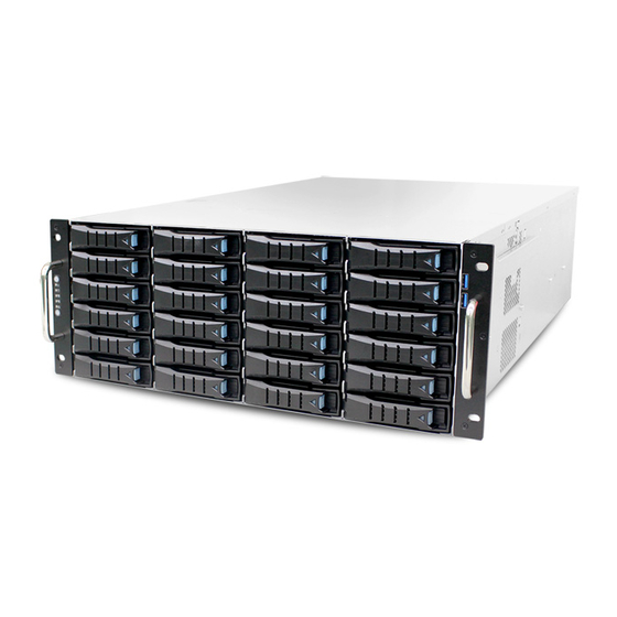
Chapter 1 Product Features 1�3 Features SB401-LB is a reliable 4U storage server barebone with 24 hotswap drives bays. This product is designed to accommodate the AIC-patented serverboard, Libra, which sup- ports two Intel® Xeon® Processors E5-2600 v3 and v4 processors and 16 DDR4 DIMM to offer greater perfomance, efficiency, and utility for our customers. - Page 11 Chapter 1 Product Features Front Panel 2 x USB3.0 ports 24 x 3.5” hotswap HDD trays SB401-LB User's Manual...
- Page 12 Chapter 1 Product Features Rear Panel SB401-LB User's Manual...
- Page 13 Chapter 1 Product Features Major Components SB401-LB User's Manual...
-
Page 14: Chapter 2� Hardware Setup
(1b) Proceed to screw 2 and loosen it by giving it two rotations and stop (see letter B). Similarly, loosen screws 3 and 4. Repeat steps A and B by giving each screw two rotations each time until all the screws are loosened. (1c) Lift the heatsink upward (see letter C). SB401-LB User's Manual... - Page 15 (1) Touch the metal chassis before touching the processor or server board. Keep part of your body in contact with the metal chassis to dissipate the static charge while handling the processor. (2) Avoid moving around unnecessarily. SB401-LB User's Manual...
- Page 16 The processor must align correctly with the socket opening before installation. DO NOT DROP the processor into the socket. NOTE : When possible, a CPU insertion tool should be used when installing the CPU. SB401-LB User's Manual...
- Page 17 Make sure the load plate tab engages under the socket lever when fully closed. (4b) Repeat the steps to latch the locking lever on the other side (see letter C). Latch the levers in the order as demonstrated. SB401-LB User's Manual...
- Page 18 (see letter D). Similarly, engage screws 3 and 4. (5c-3) Repeat steps C and D by giving each screw two rotations each time until each screw is lightly tightened up to a maximum of 8 inch-lbs torque (see letter E). CAUTION: Do not over-tighten fasteners. SB401-LB User's Manual...
- Page 19 Caution - Possible thermal damage. Avoid moving the heatsink after it has contacted the top of the CPU. Too much movement could disturb the layer of thermal compound, causing voids, and leading to ineffective heat dissipation and component damage. SB401-LB User's Manual...
-
Page 20: 2�2 System Memory
JDIMMD1 JDIMME0 JDIMMD0 JDIMMC1 JDIMMC0 JBMC_DP note : Slot 1 / Slot 3 Available ONLY When JCPU0 processor is installed. Slot 2 / Slot 4 / Slot 5 /Slot 6 Available ONLY When JCPU1 processor is installed. SB401-LB User's Manual... - Page 21 JDIMMD1 JDIMMF0 JDIMMD0 JDIMME1 JDIMMC1 JDIMMC0 JDIMME0 JDIMMG0 JDIMMA0 JDIMMG1 JDIMMA1 JDIMMB0 JDIMMH0 JDIMMB1 JDIMMH1 CPU1 CPU0 JDIMM_G0 JDIMM_A0 8 DIMMs JDIMM_H0 JDIMM_B0 CPU0 CPU1 JDIMM_F0 JDIMM_D0 JDIMM_E0 JDIMM_C0 JDIMMF1 JDIMMD1 JDIMMF0 JDIMMD0 JDIMME1 JDIMMC1 JDIMME0 JDIMMC0 SB401-LB User's Manual...
- Page 22 JDIMMA0 CPU1 CPU0 JDIMMG1 JDIMMA1 JDIMMH0 JDIMMB0 JDIMM_G0 JDIMM_A0 JDIMMH1 JDIMMB1 JDIMM_G1 JDIMM_A1 JDIMM_H0 JDIMM_B0 16 DIMMs JDIMM_H1 JDIMM_B1 CPU0 CPU1 JDIMM_F1 JDIMM_D1 JDIMM_F0 JDIMM_D0 JDIMM_E1 JDIMM_C1 JDIMMF1 JDIMMD1 JDIMMF0 JDIMMD0 JDIMM_E0 JDIMM_C0 JDIMME1 JDIMMC1 JDIMME0 JDIMMC0 SB401-LB User's Manual...
- Page 23 2.2.2 DIMM Installation Procedure Unlock a DIMM socket by pressing the retaining clips outward. Insert module vertically and press down until it snaps into place. Note: DIMM notch and socket bump must align as shown. DIMM notch SB401-LB User's Manual...
-
Page 24: 2�3 Removing And Installing The Chassis Top Cover
Step 1 Push the button on both sides. Step 2 Push the top cover towards the rear panel and lift up the cover from the enclosure. 2.3.2 Installing the chassis top cover Slide the top cover into the enclosure. SB401-LB User's Manual... -
Page 25: 2�4 Removing And Installing The Hard Disk Drive
Place the HDD into tool-less HDD tray untli it snaps. Please check if the screw holes on HDD match the dimples on HDD tray. HDD can also be secured in the HDD tray by fastening two screws as picture showed. SB401-LB User's Manual... - Page 26 2.4.2 Insert the drive tray into chassis HDD cage. Make sure the drive tray is correctly secured in place when its front edge aligns with the edge of the bay. Push the tray lever until it reaches the end and clicks. SB401-LB User's Manual...
-
Page 27: 2�5 Removing And Installing The Fan Module
Chapter 2 Hardware Setup 2�5 Removing and Installing the Fan Module 2.5.1 Removing the fan module Pull the fan module out of the fan slot. SB401-LB User's Manual... - Page 28 Chapter 2 Hardware Setup 2.5.2 Installing the fan module Make sure the 4 rubbers and connector are inserted firmly into the enclosure. SB401-LB User's Manual...
-
Page 29: 2�6 Removing And Installing The Hdd Backplane Module
2�6 Removing and Installing the HDD Backplane Module 2.6.1 Removing the HDD backplane Step 1 Unplug all the connectors and HDDs from HDD backplane. Step 2 Release the lock pin. Step 3 Remove the blackplane by moving the hook. SB401-LB User's Manual... - Page 30 Chapter 2 Hardware Setup 2.6.2 Installing the HDD backplane module Step 1 Align the backplane with the hooks, and insert it into the enclosure firmly. Step 2 Lock the backplane and secure it with screws SB401-LB User's Manual...
-
Page 31: 2�7 Removing And Installing The Power Supply Unit Module
Step 1 Removing power cable and loosen the thumb screw. Step 2 Pushing the latch and hold the tray handle. Step 3 Pull the PSU module tray handle out gently to slides out the PSU module. 2.7.2 Installing the power supply unit module SB401-LB User's Manual... -
Page 32: 2�8 Removing And Installing The Pcie Card
Step 3 Take the card and check for downside printedbord connectors. Keep the connector side downward. ' Check the location below before inserting the PCIe card: 1. Locate external connector side of card. 2. Locate right downside of the card . 3. Locate the PCI Slot SB401-LB User's Manual... - Page 33 Step 5 Press firmly to completely insert the card into the PCI slot and the screws in enclosure. Step 6 Check your earthing is working properly . Step 7 Turn on your system. It will automatically detect new hardware. SB401-LB User's Manual...
Need help?
Do you have a question about the SB401-LB and is the answer not in the manual?
Questions and answers