
Subscribe to Our Youtube Channel
Related Manuals for AIC SB402-CP2


Summary of Contents for AIC SB402-CP2
- Page 1 SB402-CP2 Storage Server Barebone User Manual Document Number: MAN-00113-A P/N: H884BC9002-00001-0...
-
Page 2: Table Of Contents
CHAPTER 1. PRODUCT INTRODUCTION ............6 1.1 General Information ................6 1.2 System Specifications ................7 1.3 Front View of SB402-CP2 ..............9 1.4 Rear View of SB402-CP2 ..............9 1.5 Top View of SB402-CP2 ..............10 CHAPTER 2. HARDWARE SETUP ..............11 2.1 Chassis Cover .................. - Page 3 3.4 Intel® Server Board S2600CP Jumper Blocks ......... 26 3.5 Rear I/O Layout ..................27 CHAPTER 4. INTEL® SERVER BOARD S2600CP PLATFORM MANAGEMENT ..................... 28 4.1 Server Management Function Architecture ........28 4.1.1 Feature Support ..............28 4.1.2 Basic and Advanced Features ..........31 4.1.3 Integrated BMC Hardware: Emulex* Pilot III ......
- Page 4 4.7 EU Lot 6 Mode ..................59 4.7.1 Impact to System Features ..........60 CHAPTER 5. TECHNICAL SUPPORT ............61 Copyright © 2013 AIC, Inc. All Rights Reserved. This document contains proprietary information about AIC products and is not to be disclosed or used except in...
-
Page 5: Safety Information
Safety Information When installing, operating, or performing maintenance on this equipment, the following safety precautions should always be followed to reduce the risk of fire, electric shock, and personal injuries. Read and understand all instructions. Observe warnings and instructions marked on the product. ... -
Page 6: About This User Manual
About This User Manual SB402-CP2 This document provides a detailed description of the including: General Features of the Product Hardware Setup Motherboard Settings BIOS Configuration and Settings BMC Configuration and Settings... -
Page 7: Chapter 1. Product Introduction
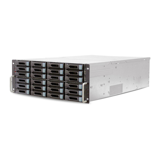
Xeon processors E5-2600/E5-2600 v2 series. SB402-CP2 has 36 x 3.5” in the front and 2 x 2.5” size HDD bays in the rear side as system drive bays. It is a perfect building block for Storage Servers. System Package Contents... -
Page 8: System Specifications
1.2 System Specifications Dimensions (including chassis ears/protrusions) mm : 483 X 679 X 173.5 W x D x H inches : 19 X 26.7 X 7 Motherboard Intel® Server Board S2600CP2 Processor ▪ Dual LGA 2011 (Socket –R) ▪ Supports two Intel® 2S Xeon® E5-2600/E5-2600 v2 Processors ▪... - Page 9 ▪ 1 x DH-10 serial Port B connector ▪ 1 x 1x7pin header for optional Intel® Local Control Panel support Rear I/O ▪ 1 x DB-15 VGA output ▪ 1 x external DB9 serial port ▪ 2 x RJ-45 10/100/1000Mb ethernet ports ▪...
-
Page 10: Front View Of Sb402-Cp2
1.3 Front View of SB402-CP2 System Icon Color Controls Icon System Behavior Behavior Solid: System Power Power Push for Power Green On Off: ON/OFF On or Off System Off Push for System Light: Link System Reset Non- LAN LED Green... -
Page 11: Top View Of Sb402-Cp2
1.5 Top View of SB402-CP2 3.5” HDD easy swap fans Intel S2600CP2 MB Rear I/O 3.5” HDD... -
Page 12: Chapter 2. Hardware Setup
Chapter 2. Hardware Setup This section illustrates the maintenance procedures for replacing a defective part once the SB402- CP2 appliance is installed and operational. 2.1 Chassis Cover 2.1.1 Removing the Chassis Cover 1. Loosen screws on the rear side. 2. Slide the cover backwards to remove it from the chassis. 2.2 Central Processing Unit (CPU) Caution: When unpacking a processor, hold the processor only by its edges to avoid touching the contacts. -
Page 13: Installing The Cpu
2.2.1 Installing the CPU A. Open the Socket Lever NOTE: Release the levers in the order as shown Push down the lever handle on the OPEN 1st side and away from the socket to release it. Repeat the steps to release the lever on the other side. B. - Page 14 C. Install the Processor Caution: The underside of the processor has components that may damage the socket pins if installed improperly. Processor must align correctly with the socket opening before installation. DO NOT DROP processor into the socket! Take the processor out of the box and remove the protective shipping cover. Orient the processor with the socket so that the processor cutouts match the four orientation posts on the socket.
-
Page 15: Installing The Cpu Heatsink
2.2.2 Installing the CPU Heatsink Caution: The heat sink has thermal interface material (TIM) on the underside of it. Use caution so that you do not damage the thermal interface material. Use gloves to avoid sharp edges. 1. Get heat sink from the shipping position. 2. -
Page 16: Diagram Of The Correct Installation
2.2.3 Diagram of the Correct Installation NOTE: The heat sink’s fans should be blowing toward the rear end of the chassis. If one of the fans is facing the wrong direction, please remove the heat sink and reinstall it so that it is facing the correct direction. AIRFLOW AIRFLOW... -
Page 17: System Memory
2.3 System Memory 2.3.1 Supported Memory UDIMM Support Speed (MT/s) and Voltage Validated by Slot per Channel (SPC) and DIMM Per Channel (DPC) Ranks Per Memory Capacity Per DIMM and Intel® Server Board S2600CP (2 Slots per Channel) DIMM Data Width 1DPC 2DPC 1.35V... -
Page 18: Memory Population Rules
LRDIMM Support Speed (MT/s) and Voltage Validated by Slot per Channel (SPC) and DIMM Per Channel (DPC) Ranks Per Memory Capacity DIMM and Data Intel® Server Board S2600CP (2 Slots per Channel) Per DIMM Width 1DPC and 2DPC 1.35V 1.5V QRx4 1066 1066, 1333... - Page 19 The following are common DIMM population requirements that generally apply to both Intel® Server Board S2600CPs. The “farthest fill first” rule must be followed when filling DIMM slots on any memory channel. A maximum of 8 ranks can be installed on any one channel (includes all ranks in each DIMM on the channel).
-
Page 20: Publishing System Memory
2 DPC QR Low Voltage RDIMMs are not supported. In order to install 3 QR LRDIMMs on the same channel, they must be operated with Rank Multiplication as RM = 2. RAS Modes Lockstep, Rank Sparing, and Mirroring are mutually exclusive in this BIOS. ... -
Page 21: Drive Bays
2.4 Drive Bays 2.4.1 Installing or Replacing 3.5” Hot-swap SAS/SATA HDD 1. Release a drive tray by pushing the unlock button to open the latch. 2. Firmly grasp the tray latch and pull the drive out of the drive slot. 3. -
Page 22: System Fans
2.5 System Fans 2.5.1 Removing or Replacing the Upper Level System Fans Firmly grasp the fan lever and pull the fan out of the server chassis. 2.5.2 Removing or Replacing the Lower Level System Fans 1. Unscrew the four screws on either side. 2. -
Page 23: Power Supply
2.6 Power Supply 2.6.1 Removing or Replacing the Power Supply Module Firmly grasp the PSU lever and pull the PSU out of the server chassis. -
Page 24: Chapter 3. Motherboard Settings
Chapter 3. Motherboard Settings This section describes the jumpers, internal connectors and internal LEDs settings on Intel S2600CP2 motherboard. Motherboard layout and important jumper settings are listed below. 3.1 Motherboard Layout... -
Page 25: Motherboard Block Diagram
3.2 Motherboard block diagram 3.3 Internal Connectors Callout Description Callout Description Slot 1, PCI Express* Gen3 System Fan 4 connector RMM4 LITE Internal eUSB SSD RMM4 NIC Slot 2, PCI Express* Gen3 System Fan 2 Slot 3, PCI Express* Gen3, open-ended System Fan 1 (blue connector) Slot 4, PCI Express* Gen3... - Page 26 Diagnostic LED SATA SGPIO Callout Description Callout Description NIC 3/4 (only on Intel® Server Board SATA/SAS 3G connector (NOT available S2600CP4) on Intel® Server Board S2600CP2J) USB 0/1/2/3, NIC 1,2 SAS SGPIO 2 Password Clear Serial Port A SAS SGPIO 1 Processor 2 Fan connector IPMB Processor 2 Power connector...
-
Page 27: Intel® Server Board S2600Cp Jumper Blocks
3.4 Intel® Server Board S2600CP Jumper Blocks The server boards have several 3-pin jumper blocks that you can use to configure, protect, or recover specific features of the server boards. The following symbol identifies Pin 1 on each jumper block on the silkscreen: ▼ Server Board Jumpers (J1D3, J1D2, J1E3, J1E4, J1F1) Jumper Name Pins... -
Page 28: Rear I/O Layout
Jumper Name Pins System Results BMC Firmware Force Update Mode – Disabled (Default) J1E4: BMC BMC Firmware Force Update Mode – Enabled Force Update These pins should have a jumper in place for normal system operation. (Default) J1F1: To clear administrator and user passwords, power on the system with pins 2-3 Password Clear connected. -
Page 29: Chapter 4. Intel® Server Board S2600Cp Platform Management
Chapter 4. Intel® Server Board S2600CP Platform Management 4.1 Server Management Function Architecture 4.1.1 Feature Support 4.1.1.1 IPMI 2.0 Features The IPMI 2.0 features are as follows: Baseboard management controller (BMC) IPMI Watchdog timer Messaging support, including command bridging and user/session support. ... - Page 30 4.1.1.2 Non-IPMI features The BMC supports the following non-IPMI features. This list does not preclude support for future enhancements or additions. In-circuit BMC firmware updating Fault resilient booting (FRB): FRB2 is supported by the watchdog timer functionality. Chassis intrusion detection (dependent on platform support) ...
- Page 31 4.1.1.3 New Manageability Features Intel® S2600CP Server Platforms offer a number of changes and additions to the manageability features that are supported on the previous generation of servers. The following is a list of the more significant changes that are characteristic to this generation of Integrated BMC based Intel® Server boards: ...
-
Page 32: Basic And Advanced Features
4.1.2 Basic and Advanced Features The bellowing table lists basic and advanced feature support. Individual features may vary by platform. See the appropriate Platform Specific EPS addendum for more information. Basic and Advanced Features Feature Basic Advanced IPMI 2.0 Feature Support ... - Page 33 Sixteen fan tachometers Eight Pulse Width Modulators (PWM) Chassis intrusion logic JTAG Master Eight I2C interfaces with master-slave and SMBus* timeout support. All interfaces are SMBus* 2.0 compliant. Parallel general-purpose I/O Ports (16 direct, 32 shared) ...
- Page 34 4.1.3.1.3 Remote Keyboard, Video, Mouse, and Storage (KVMS) The Integrated BMC contains a remote KVMS subsystem with the following features: USB 2.0 interface for Keyboard, Mouse, and Remote storage such as CD/DVD ROM and floppy USB 1.1/USB 2.0 interface for PS2 to USB bridging, remote Keyboard and Mouse ...
-
Page 35: Server Management Functional Specifications
4.2 Server Management Functional Specifications 4.2.1 BMC Internal Timestamp Clock The BMC maintains an internal timestamp clock that is used by various BMC subsystems for time stamping SEL entries. As part of BMC initialization after AC power is applied or the BMC is reset, the BMC initializes this internal clock to the value retrieved from the SSB component‟s RTC by a SMBus* slave read operation. -
Page 36: Field Replaceable Unit (Fru) Inventory Device
4.2.3 Field Replaceable Unit (FRU) Inventory Device The BMC implements the interface for logical FRU inventory devices as specified in the Intelligent Platform Management Interface Specification, Version 2.0. This functionality provides commands used for accessing and managing the FRU inventory information. These commands can be delivered through all interfaces. -
Page 37: Diagnostic Interrupt (Nmi) Button
4.2.5 Diagnostic Interrupt (NMI) Button The BMC generates an NMI pulse under certain conditions. The BMC-generated NMI pulse duration is at least 30 ms. Once an NMI has been generated by the BMC, the BMC does not generate another NMI until the system has been reset or powered down. -
Page 38: Sensor Monitoring
Note: A reset of the BMC may result in the following system degradations that will require a system reset or power cycle to correct: 1. Timeout value for the rotation period can be set using this parameter; potentially incorrect ACPI Power State reported by the BMC. 2. - Page 39 -[u,l][nr,c,nc] upper non-recoverable, upper critical, upper non-critical, lower non-recoverable, lower critical, lower non-critical uc, lc upper critical, lower critical Event triggers are supported event-generating offsets for discrete type sensors. The offsets can be found in the Generic Event/Reading Type Code or Sensor Type Code tables in the Intelligent Platform Management Interface Specification Second Generation Version 2.0, depending on whether the sensor event/reading type is a generic or a sensor-specific response.
-
Page 40: Bmc System Management Health Monitoring
4.3.3 BMC System Management Health Monitoring The BMC tracks the health of each of its IPMI sensors and report failures by providing a “BMC FW Health” sensor of the IPMI 2.0 sensor type Management Subsystem Health with support for the Sensor Failure offset. - Page 41 requirements, primarily memory bandwidth. The BIOS, BMC, and SDRs work together to provide control over how this trade-off is determined. This capability requires the BMC to access temperature sensors on the individual memory DIMMs. Additionally, closed-loop thermal throttling is only supported with buffered DIMMs. The server board offers multiple thermal and acoustic management features to maintain comprehensive thermal protection as well as intelligent fan speed control.
-
Page 42: Thermal Sensor Input To Fan Speed Control
4.3.6 Thermal Sensor Input to Fan Speed Control The BMC uses various IPMI sensors as input to the fan speed control. Some of the sensors are IPMI models of actual physical sensors, whereas some are “virtual” sensors whose values are derived from physical sensors using calculations and/or tabular information. -
Page 43: Power Supply Status\Health Sensors
High-level Fan Speed Control Process 4.3.7 Power Supply Status\Health Sensors The BMC supports one Power Supply Status sensor for each system power supply module. In order to track problems in which the PSU firmware is not operating to full capacity, an additional case (degraded condition if the PSU firmware is not operating to full capacity) is added to the existing Power Supply Status sensor offset definitions. - Page 44 Offset Description Event Logging Power supply failure detected – Asserted if power supply module has failed. The following codes for failure modes are put into the SEL Event Data 2 byte: 01h - Output voltage fault 02h - Output power fault 03h - Output over-current fault 04h - Over-temperature fault Assertion and...
-
Page 45: System Event Sensor
4.3.8 System Event Sensor The BMC supports a System Event sensor and logs SEL event for following events. Support System Event Sensor Offsets Offset Description Event Logging Assertion and OEM code (Undetermined system HW failure) De-assertion PEF action Assertion only For offset 2, OEM code will be logged in event data byte 2 to indicate the type of failure. -
Page 46: Channel Management
4.4.1 Channel Management Every messaging interface is assigned an IPMI channel ID by IPMI 2.0. Commands are provided to configure each channel for privilege levels and access modes. Table 21 shows the standard channel assignments: Standard Channel Assignments Supports Channel ID Interface Sessions Primary IPMB... - Page 47 Run-time determination of LAN channel capabilities can be determined by both standard IPMI defined mechanisms. 4.4.3.1 IPMI 1.5 Messaging The communication protocol packet format consists of IPMI requests and responses encapsulated in an IPMI session wrapper for authentication. It is wrapped in an RMCP packet, which is wrapped in an IP/UDP packet.
- Page 48 Supported RMCP+ Payload Types Payload Type Feature IANA IPMI message Serial-over-LAN OEM explicit Intel (343) 10h – 15h Session setup 4.4.3.3 RMCP/ASF Messaging The BMC supports RMCP ping discovery, in which the BMC responds with a pong message to an RMCP/ASF ping request.
- Page 49 Provided the HW supports a management link between the BMC and a NIC port, the BMC FW supports concurrent OOB LAN management sessions for the following combination: Two on-board NIC ports One on-board NIC and the optional dedicated add-in management NIC ...
- Page 50 4.4.3.6 IPV6 Support In addition to IPv4, Intel® S2600CP Server Board supports IPv6 for manageability channels. Configuration of IPv6 is provided by extensions to the IPMI Set and Get LAN Configuration Parameters commands as well as through a Web Console IPv6 configuration web page. The BMC supports IPv4 and IPv6 simultaneously, so they are both configured completely independent of one another.
- Page 51 Only one VLAN can be enabled at any point in time on a LAN channel. If an existing VLAN is enabled, it must first be disabled prior to configuring a new VLAN on the same LAN channel. Parameter 21 (VLAN Priority) of the Set LAN Config Parameters IPMI command is now implemented and a range from 0-7 will be allowed for VLAN Priorities.
- Page 52 Factory Configured PEF Table Entries Event Filter Offset Mask Events Number Non-critical, critical and nonrecoverable Temperature sensor out of range Non-critical, critical and nonrecoverable Voltage sensor out of range Non-critical, critical and nonrecoverable Fan failure General chassis intrusion Chassis intrusion (security violation) Failure and predictive failure Power supply failure Uncorrectable ECC...
- Page 53 policy table because the destination types and alerts may vary by user. Each entry in the alert policy table contains four bytes for a maximum table size of 80 bytes. 4.4.3.15.1 E-mail Alerting The Embedded Email Alerting feature allows the user to receive e-mails alerts indicating issues with the server.
- Page 54 Power on/off/reset the server and view current power state. Displays BIOS, BMC, ME, and SDR version information. Display overall system health. Configuration of various IPMI over LAN parameters for both IPv4 and IPv6. Configuration of alerting (SNMP and SMTP). ...
- Page 55 For Reset by Virtual Front Panel, the reset will be done by a Chassis Control command. For Reset by Virtual Front Panel, the restart cause will be because of Chassis Control command. During Power action, Power button/Reset button should not accept the next action until current Power action is complete and the acknowledgment from BMC is received.
-
Page 56: Advanced Management Feature Support
The Lightweight Directory Access Protocol (LDAP) is an application protocol supported by the BMC for the purpose of authentication and authorization. The BMC user connects with an LDAP server for login authentication. This is only supported for non-IPMI logins including the embedded web UI and SM-CLP. IPMI users/passwords and sessions are not supported over LDAP. -
Page 57: Keyboard, Video, Mouse (Kvm) Redirection
4.5.2 Keyboard, Video, Mouse (KVM) Redirection The BMC firmware supports keyboard, video, and mouse redirection (KVM) over LAN. This feature is available remotely from the embedded web server as a Java applet. This feature is only enabled when the Intel® RMM4 lite is present. The client system must have a Java Runtime Environment (JRE) version 6.0 or later to run the KVM or media redirection applets. -
Page 58: Intel® Intelligent Power Node Manager (Nm)
The media redirection feature is intended to allow system administrators or users to mount a remote IDE or USB CD-ROM, floppy drive, or a USB flash disk as a remote device to the server. Once mounted, the remote device appears just like a local device to the server, allowing system administrators or users to install software (including operating systems), copy files, update BIOS, and so on, or to boot the server from this device. -
Page 59: Hardware Requirements
implements specific data center power management usage models such as power limiting and thermal monitoring. Note: Support for NM is product-specific. This section details how NM would be supported on products that provide this capability. The NM feature is implemented by a complementary architecture utilizing the ME, BMC, BIOS, and an ACPI-compliant OS. -
Page 60: Smart/Clst
4.6.4 SmaRT/CLST The power supply optimization provided by SmaRT/CLST relies on a platform HW capability as well as ME FW support. When a PMBus*-compliant power supply detects insufficient input voltage, an overcurrent condition, or an over-temperature condition, it will assert the SMBAlert# signal on the power supply SMBus* (that is, the PMBus*). -
Page 61: Impact To System Features
4.7.1 Impact to System Features The following system features are lost or impacted when EU Lot6 mode is enabled: Increased boot time (~15-20s) when system is DC power cycled. This is due to the fact that both the BMC and BIOS are booting at the same time when the system is powered on (to S0 state). -
Page 62: Chapter 5. Technical Support
Chapter 5. Technical Support TAIWAN Tel: +886.3.313.8386 Fax: +886.3.313.8377 Email Technical Support: support@aicipc.com JAPAN Tel: +81.43.202.8380 Fax: +81.43.202.8381 Email Technical Support: support@aicipc.com CHINA Tel: +021.54961421, +021.54961422 Fax: Extension: 608 Email Technical Support: support@aicipc.com - West coast AMERICA Tel: +1.909.895.8989 Fax: +1.909.895.8999... - Page 63 Note...
Need help?
Do you have a question about the SB402-CP2 and is the answer not in the manual?
Questions and answers