Table of Contents
Advertisement
Quick Links
Advertisement
Table of Contents

Related Manuals for AIC HP201-AD


Summary of Contents for AIC HP201-AD
- Page 1 HP201-AD Storage Server Barebone User's Manual UM_HP201-AD_v.1_050217...
-
Page 2: Table Of Contents
4�1 Updating BIOS �����������������������������������������������������������������������������������46 Chapter 5. BMC Configuration and Settings ��������������������������� 48 5�1 Method 1 (Use the BIOS setup) �������������������������������������������������������49 5�2 Method 2 (Use a Dos tool - Syscheck) �������������������������������������������54 5�3 BMC web-browser-MegaRAC® GUI Overview �����������������������������56 HP201-AD User's Manual contents... - Page 3 Chapter 6� Hardware Introduction ������������������������������������������� 62 6�1 BACKPLANE HARDWARE INTRODUCTION ����������������������������������������62 6�2 Drive Slot Map �����������������������������������������������������������������������������������66 Chapter 7� Technical Support��������������������������������������������������� 67 contents...
- Page 4 Copyright © 2017 AIC, Inc� All Rights Reserved� This document contains proprietary information about AIC products and is not to be disclosed or used except in accordance with applicable agreements. HP201-AD User's Manual...
-
Page 5: Preface
AIC shall not be liable for technical or editorial errors or omissions contained herein. The information provided is provided "as is" without warranty of any kind. To the extent permitted by law, neither AIC or its affiliates, subcontractors or suppliers will be liable for incidental, special or consequential damages including downtime cost;... -
Page 6: Safety Instructions
Pay special attention to power supplied other than direct connections, e.g. using of power strips. • Place the power cord out of the way of foot traffic. Do not place anything over the power cord. The power cord must be rated for the HP201-AD User's Manual... - Page 7 • product, voltage and current marked on the product’s electrical ratings label. The voltage and current rating of the cord should be greater than the voltage and current rating marked on the product. • If the equipment is not used for a long time, disconnect the equipment from mains to avoid being damaged by transient over-voltage.
-
Page 8: Chapter 1� Prodcut Introduction
• Enclosure( Power supply, fan, 24 x 2.5'' HDD tray included) • 2.5’’ HDD Tray • Power cord • Screws kit x 1set • Slide rail x 1set ♦ PACKAGE CONTENT MAY VARY PER REGION. HP201-AD User's Manual... -
Page 9: 1.2 Specifications
Chapter 1 Product Introduction 1.2 Specifications HP201-AD User's Manual... -
Page 10: 1�3 General Information
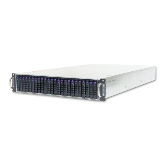
Chapter 1 Product Introduction 1�3 General Information HP201-AD is a 2U Storage Server Barebone with Motherboard Aidos/ 24x2.5” NVMe/SAS hybrid drives(6 per node) and single 12G expander on HDD Backplane which is a high performance Storage Server Barebone. • Front Panel... - Page 11 Chapter 1 Product Introduction • Rear Panel 1600W/2000W Hot-Swappable 1+1 redundant PSU 4 x PCIe 3.0 slots (per node) Low-profile(HHHL) card per node 2 x 10 GbE SFP+ HP201-AD User's Manual...
- Page 12 Chapter 1 Product Introduction • Major Components 24 x 2.5” NVMe/SAS hybrid drives(6 per node) 2U 4 x AIC Aidos base E5 server node 1600W/2000W 1+1 Redundant PSU HP201-AD User's Manual...
-
Page 13: Chapter 2� Hardware Installation
• Proceed to screw 2 and loosen it by giving it two rotations and stop (see letter B). Similarly, loosen screws 3 and 4. Repeat steps A and B by giving each screw two rotations each time until all screws are loosened. • Lift the heatsink straight up (see letter C). HP201-AD User's Manual... - Page 14 2.1.2.1 Unlatch the CPU Load Plate • Push the lever handle labeled “OPEN 1st” (see letter A) down and toward the CPU socket. Rotate the lever handle up. • Repeat the steps for the second lever handle (see letter B). HP201-AD User's Manual...
- Page 15 2.1.2.2 Lift open the Load Plate • Rotate the right lever handle down until it releases the Load Plate (see letter A). • While holding down the lever handle, with your other hand, lift open the Load Plate (see letter B). HP201-AD User's Manual...
- Page 16 The processor must align correctly with the socket opening before installation. DO NOT DROP the processor into the socket. NOTE : When possible, a CPU insertion tool should be used when installing the CPU. HP201-AD User's Manual...
- Page 17 Make sure the load plate tab engages under the socket lever when fully closed. • b.Repeat the steps to latch the locking lever on the other side (see letter C). Latch the levers in the order as shown. HP201-AD User's Manual...
- Page 18 (see letter D). Similarly, engage screws 3 and 4. • Repeat steps C and D by giving each screw two rotations each time until each screw is lightly tightened up to a maximum of 8 inch-lbs torque (see letter E). CAUTION: Do not over-tighten fasteners. HP201-AD User's Manual...
- Page 19 Remove the processor by carefully lifting it out of the socket, taking care NOT to drop the processor and not touching any pins inside the socket. Install the socket cover if a replacement processor is not going to be installed. HP201-AD User's Manual...
- Page 20 Caution - Possible thermal damage. Avoid moving the heatsink after it has contacted the top of the CPU. Too much movement could disturb the layer of thermal compound, causing voids, and leading to ineffective heat dissipation and component damage. HP201-AD User's Manual...
-
Page 21: 2�2 System Memory
This server board supports up to sixteen DDR4 1333/1600/1866/2133 Registered ECC SDRAM(RDIMM) / Load-Reduced DIMM (LRDIMM). CPU0_DIMMC0 CPU0_DIMME0 CPU0_DIMMC1 CPU0_DIMME1 CPU0_DIMMD0 CPU0_DIMMF0 CPU0_DIMMD1 CPU0_DIMMF1 JCPU0 JCPU1 Reset Button CPU0_DIMMB1 CPU0_DIMMH1 CPU0_DIMMB0 CPU0_DIMMH0 SATA4 CPU0_DIMMA1 CPU0_DIMMG1 SATA0~3 SATA0~3 CPU0_DIMMA0 CPU0_DIMMG0 SATA5 HP201-AD User's Manual... - Page 22 JDIMMH1 JDIMMB0 JDIMMH0 JDIMMA1 JDIMMG1 JDIMMA0 JDIMMG0 JDIMMC0 JDIMME0 JDIMMC1 JDIMME1 JDIMMF0 JDIMMD0 JDIMMF1 JDIMMD1 CPU0 CPU1 JDIMM_C0 JDIMM_E0 8 DIMMs JDIMM_D0 JDIMM_F0 CPU0 CPU1 JDIMM_B0 JDIMM_H0 JDIMM_A0 JDIMM_G0 JDIMMB1 JDIMMH1 JDIMMB0 JDIMMH0 JDIMMA1 JDIMMG1 JDIMMA0 JDIMMG0 HP201-AD User's Manual...
- Page 23 Chapter 2 Hardware Installation HP201-AD User's Manual...
- Page 24 2.2.2 DIMM Installation Procedure Unlock a DIMM socket by pressing the retaining clips outward. Insert module vertically and press down until it snaps into place. Note: DIMM notch and socket bump must align as shown. DIMM notch HP201-AD User's Manual...
-
Page 25: 2�3 Removing And Installing Chassis Top Cover
1. Loosen 14 screws securing the right side covers to the chassi. Loosen 15 screws securing the left side covers to the chassi. 2. Pull the cover slightly toward and backward of the server and then straight up to remove it. 3. Lift the cover and remove it. HP201-AD User's Manual... -
Page 26: 2�4 Removing/Installing A Drive Tray/ Hard Drive
2.4.2 Installing a 2.5'' Disk Drive Place one 2.5” HDD/SSD on the tray and then secure it with four screws on both sides of HDD tray. The mounting screw holes may vary from different type of HDDs. HP201-AD User's Manual... -
Page 27: 2�5 Replacing Single Node Server
2. Removing all cables from BP and clear the space to remove the node is an important process. 3. Slide the Node out of the cage by pushing the latch right. 4. To install Node, follow the reverse order. HP201-AD User's Manual... -
Page 28: 2�6 Removing And Installing A Fan Module
NOTE: The heat sink’s fans should be blowing toward the rear end of the chassis. If one of the fans is facing the wrong direction, please remove the heat sink and reinstall it so that it is facing the correct direction. HP201-AD User's Manual... - Page 29 Chapter 2 Hardware Installation 2.6.2 Installing a Fan Module Make sure the 4 rubbers and connector insert firmly while fan module is inserted. HP201-AD User's Manual...
-
Page 30: 2�7 Removing And Installing A Psu Module
• Pushing the latch • Hold the tray handle • Pull the PSU module tray handle out gently to slides out the PSU module. 2.7.2 Installing a PSU Module • To install PSU module, follow the reverse order. HP201-AD User's Manual... -
Page 31: 2�8 Removing And Installing The Hdd Backplane Module
• Grasp and lift up the blackplane then can get out. 2.8.2 Installing a HDD backplane module • Slide the HDD backplane module into enclosures. • Secure the HDD backplane module onto the enclosures using the screws. Follow the reverse order. HP201-AD User's Manual... -
Page 32: 2�9 Tool-Less Blade Slide Installation Introduction
Chapter 2 Hardware Installation 2�9 Tool-less Blade Slide Installation introduction 1. Pull on the ‘’Front-Release’’to unlock the inner channel from the Slide Assembly. 2. Release the Detent-Lock and push Middle Channel inwards to retract Middle Channel. HP201-AD User's Manual... - Page 33 Chapter 2 Hardware Installation Optional: Remove Metal Spacer for Aluminium Racks Metal Spacer 3. Aligning the Front Bracket with the Mounting Hole. 4. Push in to assembly the Front Bracket onto the Rack. HP201-AD User's Manual...
- Page 34 Chapter 2 Hardware Installation 5. Now the bracket is fixed onto the Rack. (Optional M6x10L screws are to secure the rails with posts if needed.) 6. Refer to Diagram 3. & 4. to assemble the End Bracket onto the Rack. HP201-AD User's Manual...
- Page 35 Chapter 2 Hardware Installation 7. Assemble the inner channel onto the chassis using thescrews provided. 8. Push the chassis with inner channels into Slide to complete Rack Installation. HP201-AD User's Manual...
-
Page 36: Chapter 3� Motherboard Settings
Chapter 3 Motherboard Setting Chapter 3� Motherboard Settings This section describes the jumpers, internal connectors, and internal LEDs setting on Libra motherboard. Motherboard layout and important jumper settings are listed as below. 3�1 Motherboard block diagram HP201-AD User's Manual... -
Page 37: 3�2 Motherboard Layout
Mode ME Force XDP CONN Recovery Mode Flash Descriptor JEDEC Specified DDR4 DIMM Sockets Security Connector override CPU Sockets AIC GPIO JCPU0 /JCPU1 Debug Port FAN Front BMC Debug MDIPHY Front mode (BMC Clear CMOS management port) HP201-AD User's Manual... -
Page 38: 3�4 Expansion Slots
Chapter 3 Motherboard Setting 3�4 Expansion Slots PCI Express 8643 CONNECT PCI Express 8643 CONNECT 82599 82599 I350 I350 PCI Express 8643 CONNECT PCI Express 8643 CONNECT _PCI Express x8 HP201-AD User's Manual... -
Page 39: 3�5 Internal Connectors/Jumpers
CPU0_DIMMC0C PU0_DIMME0 CPU0_DIMMC1 CPU0_DIMME1 CPU0_DIMMD0 CPU0_DIMMF0 SFP+ CPU0_DIMMD1 CPU0_DIMMF1 RJ45 JCPU0 JCPU1 SPI (U10) LED6 Reset Button LED10 CPU0_DIMMB1 CPU0_DIMMH1 CPU0_DIMMB0 CPU0_DIMMH0 USB 3.0 SATA4 CPU0_DIMMA1 CPU0_DIMMG1 LED7 SATA0~3 SATA0~3 CPU0_DIMMA0 CPU0_DIMMG0 SATA5 SPI (U10) Reset Button HP201-AD User's Manual... - Page 40 Chapter 3 Motherboard Setting Internal Connectors/Jumpers HP201-AD User's Manual...
- Page 41 Internal Connectors/Jumpers DCDB DSRB DACROA RXDB RTSB DACGOA RXDB TXDB CTSB DDC_DATAO DTRB TXDB KEY (no pin) DACBOA AHSYNCO DVO_5V AVSYNCO DDC_CLKO PWR_BTN- I2C1SDA CLK_33M_DP80 RST_BTN- PCH_LFRAME_N PCH_GPIO61 TXDB RST_PLTRST_N AST_SERIRQ I2C1SCL RXDB PCH_LPC_LAD3 PCH_LPC_LAD2 +3.3V PCH_LPC_LAD1 PCH_LPC_LAD0 HP201-AD User's Manual...
- Page 42 Chapter 3 Motherboard Setting Internal Connectors/Jumpers HP201-AD User's Manual...
- Page 43 CPU0_DIMMC0C PU0_DIMME0 CPU0_DIMMC1 CPU0_DIMME1 CPU0_DIMMD0 CPU0_DIMMF0 SFP+ CPU0_DIMMD1 CPU0_DIMMF1 RJ45 JCPU0 JCPU1 SPI (U10) LED6 Reset Button LED10 CPU0_DIMMB1 CPU0_DIMMH1 CPU0_DIMMB0 CPU0_DIMMH0 USB 3.0 SATA4 CPU0_DIMMA1 CPU0_DIMMG1 LED7 SATA0~3 SATA0~3 CPU0_DIMMA0 CPU0_DIMMG0 SATA5 SATA4 SATA0~3 SATA0~3 SATA5 HP201-AD User's Manual...
- Page 44 Chapter 3 Motherboard Setting Internal Connectors/Jumpers SATA5 SATA0~3 SATA0~3 SATA4 HP201-AD User's Manual...
- Page 45 Chapter 3 Motherboard Setting Internal Connectors/Jumpers +12V +12V +12V +12V +12V +5V_AUX POWER OK PS_ON# MDI_PHY1_TX_P +12V MDI_PHY1_TX_N MDI_PHY1_RX_P +12V MDI_PHY1_RX_N +12V +12V HP201-AD User's Manual...
-
Page 46: 3�6 Leds
Chapter 3 Motherboard Setting 3�6 LEDs 3.6.1 Front Panel LED Definition HP201-AD User's Manual... - Page 47 Chapter 3 Motherboard Setting 3.6.2 Rear Panel LED Definition HP201-AD User's Manual...
- Page 48 CPU0_DIMMD1 CPU0_DIMMF1 RJ45 JCPU0 JCPU1 SPI (U10) LED6 Reset Button LED10 CPU0_DIMMB1 CPU0_DIMMH1 CPU0_DIMMB0 CPU0_DIMMH0 USB 3.0 SATA4 CPU0_DIMMA1 CPU0_DIMMG1 LED7 SATA0~3 SATA0~3 CPU0_DIMMA0 CPU0_DIMMG0 SATA5 SPI (U10) LED6 Reset Button LED10 SATA4 LED7 SATA0~3 SATA0~3 SATA5 HP201-AD User's Manual...
- Page 49 Chapter 3 Motherboard Setting HP201-AD User's Manual...
-
Page 50: Chapter 4. Bios Configuration And Settings
Chapter 4. BIOS Configuration and Settings Caution: When Quiet Boot IS enabled, OEM LOGO WILL BE displayed INSTEAD OF POST MESSAGES. 1.Press ESC to run the setup procedure. 2.There will be a message “Esc is pressed.” displayed on the diagnostics screen. HP201-AD User's Manual... - Page 51 Chapter 4 BIOS Configuration and Settings 3.Identify the BIOS Version Caution: For the official released version, the last digit of the BIOS Version must end in an "0." 4.Load Optimal Default setting HP201-AD User's Manual...
- Page 52 Chapter 4 BIOS Configuration and Settings 5.Save the setting and exit the BIOS setup utility. HP201-AD User's Manual...
-
Page 53: 4�1 Updating Bios
Chapter 4 BIOS Configuration and Settings 4�1 Updating BIOS Important Notes: To identify the current BIOS version, please check out on BIOS setup. HP201-AD User's Manual... - Page 54 To use this utility, you must include the flash.bat , H2OFFT-D.exe, and bin file in the same folder. Please follow the instructions to update whole flash part: Execute flash.bat to update Flash in the DOS environment. Reboot system. HP201-AD User's Manual...
-
Page 55: Chapter 5. Bmc Configuration And Settings
Chapter 5 BMC Configuration and Settings Chapter 5. BMC Configuration and Settings Insert Ethernet LAN cable into the BMC LAN port. There are two methods to setup BMC IP: shared NIC LAN port (LAN Channel Number 8) HP201-AD User's Manual... -
Page 56: 5�1 Method 1 (Use The Bios Setup)
Chapter 5 BMC Configuration and Settings 5�1 Method 1 (Use the BIOS setup) • BIOS SETUP g Advanced g H2O IPMI Configuration g BMC Configuration g Lan Port Configuration g Dedicated g IPv4 Source g Static HP201-AD User's Manual... - Page 57 Chapter 5 BMC Configuration and Settings HP201-AD User's Manual...
- Page 58 Chapter 5 BMC Configuration and Settings HP201-AD User's Manual...
- Page 59 Chapter 5 BMC Configuration and Settings 2. Input IP address. Set static IP. HP201-AD User's Manual...
- Page 60 Chapter 5 BMC Configuration and Settings 3. Input subnet mask address. HP201-AD User's Manual...
-
Page 61: 5�2 Method 2 (Use A Dos Tool - Syscheck)
5�2 Method 2 (Use a Dos tool - Syscheck) 1. Type : sc –lanset 2. Modify IP setting Note: type 1 for selecting static IP mode or type 2 for selecting DHCP mode. 3. Input IP address HP201-AD User's Manual... - Page 62 Below IP address is an example using a default IP setting. User is allowed to change the IP address for realistic use. 5. Finish BMC IP configuration. Note: Type sc.exe –langet command to obtain BMC IP and MAC address. HP201-AD User's Manual...
-
Page 63: 5�3 Bmc Web-Browser-Megarac® Gui Overview
It has a low learning curve because it uses standard Internet browsers. • This chapter allows you to become familiar with the MegaRAC® GUI’s various functions. Each function is described in detail. note : Your MegaRAC® GUI may not exactly match this document. HP201-AD User's Manual... - Page 64 Chapter 5 BMC Configuration and Settings 5.3.1 Supported Browsers Operating System Browser Version Linux Windows MAC OS Firefox 2.0 and above Yes-Default Internet 7 and above Yes-Default Explorer Safari 3.0 and above Yes-Default Chrome 2.0 and above Opera 9.64 and above HP201-AD User's Manual...
- Page 65 • Ubuntu 9.10 LTS – 64 • Ubuntu 8.10 -32 • Ubuntu 8.10 -64 • OpenSuse 11.2 -32 • OpenSuse 11.2 -64 • FC 9 – 32 and above • FC 9 – 64 and above • MAC -32 • MAC-64 HP201-AD User's Manual...
- Page 66 Forgot Password: If you forget your password, you can generate a new one using this link. Enter the username, click on Forgot Password link. This will send the newly generated password to the configured Email-ID for the user. HP201-AD User's Manual...
- Page 67 Enable javascript for this site: The icon indicates whether the javascript setting is enabled in browser. Enable cookies for this site: The icon indicates whether the cookies setting are enabled in browser. note : Cookies must be enabled in order to access the website. HP201-AD User's Manual...
- Page 68 Once you login to the application, it is recommended not to use the following options. -Refresh button of the browser -Refresh menu of the browser -Back and Forward options of the browser -F5 on the keyboard -Backspace on the keyboard HP201-AD User's Manual...
-
Page 69: Chapter 6� Hardware Introduction
6.1.1 Backplane Layout JPWR1 JFRONT JFRONT NODE D NODE B JPWR2 JPMBUS JPMBUS JPWR3 JPWR3 NODE C NODE C NODE A NODE A JACTN17 JPSONJ NB_CPLD JACTN6 JNC_CPLD JSGPIO JACTN24 JACTN23 JACTN11 JFROMHDD JND_CPLD JACTN12J NA_CPLD JACTN5 JACTN18 HP201-AD User's Manual... - Page 70 Chapter 6 Hardware Introduction 6.1.2 Internal Connectors/Jumpers Power Supply Connector - JPWR1.JPWR3 Power Supply Connector - JPWR2 +3V3 +5VSTBY +5VSTBY PMBUS Connector - JPMBUS Front I/O - JFRONT I2C8SCL I2C8SDA PMBUS_ALERT_N +3V3 PSU_ON POWER_OK HP201-AD User's Manual...
- Page 71 Default low CPLD,JNB.JNC.JND) SGPIO_EN SGPIO Support(JSGPIO) Default low FROMHDD LED Control Selection Default low (JFROMHDD) POWER_ON PSU_PON Default POWER_ON PS_ON Selection (JPSON) JACTN17 JPSONJ NB_CPLD JACTN6 JNC_CPLD JSGPIO JACTN24 JACTN23 JACTN11 JFROMHDD JND_CPLD JACTN12J NA_CPLD JACTN5 JACTN18 HP201-AD User's Manual...
- Page 72 HDD no connect or Power Off Off Red (On) HDD Fault or Locate HDD HDD Fault/Status LEDs Red (Blinking) Re-build status Normal JACTN17 JPSONJ NB_CPLD JACTN6 JNC_CPLD JSGPIO JACTN24 JACTN23 JACTN11 JFROMHDD JND_CPLD JACTN12J NA_CPLD JACTN5 JACTN18 HP201-AD User's Manual...
-
Page 73: 6�2 Drive Slot Map
1 2 3 4 5 6 7 8 9 10 11 12 13 14 15 16 17 18 19 20 21 22 23 24 Node 1 Node 2 Node 3 Node 4 Node 3 Node 3 Node 1 Node 4 Node 4 Node 2 Node 2 HP201-AD User's Manual... -
Page 74: Chapter 7� Technical Support
Chapter 1 Product Introduction Chapter 1 Product Introduction Chapter 7� Technical Support www�aicipc�com • TAIWAN Tel: +886 3 433 9188 Fax: +886 3 287 1818 Email : sales@aicipc�com�tw • CHINA Tel: +86�21�54961421, +86�21�54961422 Fax: Extension: 608 Email Technical Support: support@aicipc�com •...
Need help?
Do you have a question about the HP201-AD and is the answer not in the manual?
Questions and answers