Table of Contents
Advertisement
Quick Links
Download this manual
See also:
User Manual
Advertisement
Table of Contents

Related Manuals for AIC SB403-VG


Summary of Contents for AIC SB403-VG
- Page 1 SB403-VG Storage Server Barebone User's Manual UM_SB403-VG_v1.1_102218...
-
Page 2: Table Of Contents
Table of Contents Preface ������������������������������������������������������������������������������������������������� i Safety Instructions ������������������������������������������������������������������������������ ii About This Manual ������������������������������������������������������������������������������ iv Chapter 1� Product Features �������������������������������������������������������������� 1 1�1 Box Contents ������������������������������������������������������������������������������������1 1.2 Specifications������������������������������������������������������������������������������������2 1�3 Features ��������������������������������������������������������������������������������������������3 Chapter 2� Hardware Setup ���������������������������������������������������������������� 7 2�1 Central Processing Unit (CPU) �����������������������������������������������������������7 2.1.1 Processor Support ....................7 2.1.2 Processor Heat Sink Module and Processor Socket Assembly .......8 2.1.3 Processor Heat Sink Module ................9... - Page 3 2.7.1 Installing the mother board ................23 2�8 Removing and Installing the HDD Backplane Module �����������������������24 2.8.1 Installing the HDD backplane ................. 24 2.8.2 Removing the HDD backplane ................ 24 2�9 Removing and Installing the Tool-less Blade Slide ��������������������������25 Chapter 3� Hardware Settings ���������������������������������������������������������� 28 3�1 Motherboard �����������������������������������������������������������������������������������28 3.1.1 Block Diagram....................
- Page 4 Copyright © 2018 AIC, Inc� All Rights Reserved� This document contains proprietary information about AIC products and is not to be disclosed or used except in accordance with applicable agreements.
- Page 5 Document Release History Release Date Version Update Content January User's Manual release to public. 2018 1. Specifications update October 2018 2. New Cover...
-
Page 6: Preface
Disclaimer AIC shall not be liable for technical or editorial errors or omissions contained herein. The information provided is provided "as is" without warranty of any kind. To the extent permitted by law, neither AIC or its affiliates, subcontractors or suppliers will be liable for incidental, special or consequential damages including downtime cost;... -
Page 7: Safety Instructions
Safety Instructions Before getting started, please read the following important cautions: • All cautions and warnings on the equipment or in the manuals should be noted. • Most electronic components are sensitive to electrical static discharge. Therefore, be sure to ground yourself at all times when installing the internal components. •... - Page 8 • If the equipment is not used for a long time, disconnect the equipment from mains to avoid being damaged by transient over-voltage. • Never open the equipment. For safety reasons, only qualified service personnel should open the equipment. • If one of the following situations arise, the equipment should be checked by service personnel: 1.
-
Page 9: About This Manual
This document pellucidly presents a brief overview of the product design, device installation, and firmware settings for SB403-VG. For the latest version of this user's manual, please refer to the AIC website: http://www.aicipc.com/tw/productdetail/51006. -
Page 10: Chapter 1� Product Features
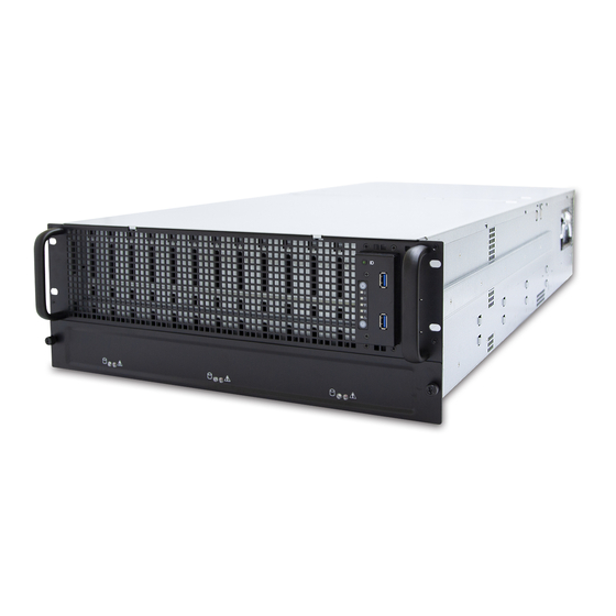
SB403-VG User Manual Chapter 1. Product Features SB403-VG is a high density storage storage server that includes a mother board, a chassis, power supply, fan, and HDD backplane. For more information about our product, please visit our website at http://www.aicipc.com/en. -
Page 11: 1.2 Specifications
SB403-VG User Manual Chapter 1. Product Features 1.2 Specifications • Insyde UEFI BIOS mm : 435 x 953 x 175.7 Dimensions • SPI (Serial Peripheral Interface) BIOS Type (W x D x H) FLASH Interface inches : 17.1 x 37.5 x 6.9 •... -
Page 12: 1�3 Features
Chapter 1. Product Features 1�3 Features SB403-VG is a reliable 4U storage server barebone with 60 hard drive disk bays that supports two Intel® Xeon® Scalable processors. This barebone consists of Intel® Lewisburg C620 series chipset, onboard baseboard management controller for system... - Page 13 SB403-VG User Manual Chapter 1. Product Features Front Panel SB403-VG provides 2 system buttons (Power & Reset) and 4 LED indicators (System power, LAN, System hard drive disk activity, Service ID). Power On/Off System Power LED LAN 1 LED LAN 2 LED...
- Page 14 SB403-VG User Manual Chapter 1. Product Features Rear Panel SB403-VG provides 3 LAN ports (10G SFP+ x 2, GbE RJ45 dedicated to BMC management), 2 USB 3.0 double stack Type A, 1 VGA port and 1 serial port.
- Page 15 SB403-VG User Manual Chapter 1. Product Features Major Components SB403-VG provides 1400W 1+1 redundant power supply 80+ Platinum and 4 hot swap fans (80 x 38mm fans x 4) & 2 easy fans (60 x 38 mm fans x 2).
-
Page 16: Chapter 2� Hardware Setup
Chapter 2� Hardware Setup SB403-VG User Manual Chapter 2. Hardware Setup 2�1 Central Processing Unit (CPU) 2�1�1 Processor Support The server board includes two processor sockets (LGA3647) and can support one or two of the Intel® Xeon® Processor Scalable Family, with a Thermal Design Power (TDP) of up to 165W on selected models. -
Page 17: Processor Heat Sink Module And Processor Socket Assembly
SB403-VG User Manual Chapter 2. Hardware Setup 2�1�2 Processor Heat Sink Module and Processor Socket Assembly Each processor socket on the server board is pre-assembled with a loading mechanism that allows to secure the placement of the Processor Heat Sink Module... -
Page 18: Processor Heat Sink Module
SB403-VG User Manual Chapter 2. Hardware Setup 2�1�3 Processor Heat Sink Module The PHM refers to the sub-assembly where the heat sink and processor are clipped together onto the server board prior to installation . The PHM consists of the components shown below. - Page 19 SB403-VG User Manual Chapter 2. Hardware Setup The PHM sits level with the processor socket assembly and is secured by four heat sink torque scews. The screws must be secured in the following order as shown below. The PHM will NOT be installed properly if it does not sit level with the processor socket assembly.
-
Page 20: Cpu Heatsink
SB403-VG User Manual Chapter 2. Hardware Setup 2�1�4 CPU heatsink CAUTION There may be possible thermal during physical contact with the heatsink. Avoid moving the heatsink after it has contacted the top of the CPU. Too much movement could disturb the layer of thermal compound, causing voids and... -
Page 21: 2�2 System Memory
SB403-VG User Manual Chapter 2. Hardware Setup 2�2 System Memory This server board supports up to twelve DDR4 2400 and 2666 Registered ECC DRAM / Load-Reduced DIMM (LRDIMM). JDIMML0 JDIMML0 JDIMMK0 JDIMMK0 JDIMMJ0 JDIMMJ0 JDIMMC0 JDIMMC0 JDIMMB0 JDIMMB0 JDIMMA0 JDIMMA0... -
Page 22: Dimm Installation Order
SB403-VG User Manual Chapter 2. Hardware Setup 2�2�1 DIMM installation Order JDIMML0 JDIMMC0 JDIMMK0 JDIMMB0 JDIMMJ0 JDIMMA0 DIMM Numbers DIMM ARRANGMENT CPU 0 CPU 0 CPU 1 CPU 1 CPU1 CPU0 2 DIMMs JDIMM_L0 JDIMM_C0 JDIMMG0 JDIMMD0 JDIMMH0 JDIMME0 JDIMMI0... - Page 23 SB403-VG User Manual Chapter 2. Hardware Setup JDIMML0 JDIMMC0 JDIMMK0 JDIMMB0 JDIMMJ0 JDIMMA0 CPU1 CPU0 JDIMM_L0 JDIMM_C0 CPU 0 CPU 0 CPU 1 CPU 1 JDIMM_K0 JDIMM_B0 10 DIMMs JDIMM_J0 JDIMM_A0 JDIMM_G0 JDIMM_D0 JDIMMG0 JDIMMD0 JDIMM_I0 JDIMM_F0 JDIMMH0 JDIMME0 JDIMMI0...
-
Page 24: Dimm Installation
SB403-VG User Manual Chapter 2. Hardware Setup 2�2�2 DIMM Installation Step 1 Unlock the DIMM socket by pressing the retaining clips outward. Step 2 Insert the memory module into the slot. Make sure that the DIMM notch is accurately positioned. -
Page 25: 2�3 Removing And Installing The Top Cover
SB403-VG User Manual Chapter 2. Hardware Setup 2�3 Removing and Installing the Top Cover 2�3�1 Installing the top cover Position the top cover onto the enclosure and push horizontally towards the adjacent top cover to install. 2�3�2 Removing the top cover Step 1 Press the release button on both sides of the enclosure. -
Page 26: 2�4 Removing And Installing The Hard Disk Drive
SB403-VG User Manual Chapter 2. Hardware Setup 2�4 Removing and Installing the Hard Disk Drive 2�4�1 Installing the 3�5" hard disk tray Push the the hard drive disk tray into the enclosure. 2�4�2 Removing the 3�5" hard disk drive tray Step 1 Place a finger inside the dent on the hard drive disk tray lever and pull upward. -
Page 27: Installing The 2.5" Hdd Tray Into The Chassis
SB403-VG User Manual Chapter 2. Hardware Setup 2�4�3 Installing the 2�5" HDD tray into the chassis Step 1 Insert the 2.5" HDD into the enclosure until it clicks. Step 2 Close the tray lever. 2�4�4 Removing the 2�5" HDD tray out of the chassis Step 1 Push the release button on the tray lever. -
Page 28: Installing The Hard Disk Drive Into The Hard Disk Drive Tray
SB403-VG User Manual Chapter 2. Hardware Setup 2�4�5 Installing the hard disk drive into the hard disk drive tray Match the dimples on the tray to insert the HDD. Make certain that the HDD is not damaged during installation or removal process. -
Page 29: 2�5 Removing And Installing The Fan Module
SB403-VG User Manual Chapter 2. Hardware Setup 2�5 Removing and Installing the Fan Module 2�5�1 Installing/removing the fan Insert or pull the fan module to install or remove. Make certain to align the fan module to the appropriate slot. -
Page 30: Installing/Removing The Fan From The Rear Panel
SB403-VG User Manual Chapter 2. Hardware Setup 2�5�2 Installing/removing the fan from the rear panel Secure or loosen the thumb screw x 1 on the fan module to install or remove. -
Page 31: 2�6 Removing And Installing The Power Supply Unit Module
SB403-VG User Manual Chapter 2. Hardware Setup 2�6 Removing and Installing the Power Supply Unit Module 2�6�1 Installing the power supply Push the tray handle on the PSU Module to install. 2�6�2 Removing the power supply Step 1 Push the latch inward and hold the tray handle. -
Page 32: 2�7 Removing And Installing The Mother Board
SB403-VG User Manual Chapter 2. Hardware Setup 2�7 Removing and Installing the Mother Board 2�7�1 Installing the mother board Step 1 Push the mother board into the enclosure. Step 2 Secure the screw x 8 pcs on both sides (screw x 4 pcs on each side) of the enclosure. -
Page 33: 2�8 Removing And Installing The Hdd Backplane Module
SB403-VG User Manual Chapter 2. Hardware Setup 2�8 Removing and Installing the HDD Backplane Module 2�8�1 Installing the HDD backplane Push the backplane module into the enclosure and close the tray lever to install. 2�8�2 Removing the HDD backplane Step 1 Open the lever on the backplane. -
Page 34: 2�9 Removing And Installing The Tool-Less Blade Slide
SB403-VG User Manual Chapter 2. Hardware Setup 2�9 Removing and Installing the Tool-less Blade Slide 1. Pulling out the inner slide rail Step 1 Press the trigger downward to release the inner side rail. Step 2 Pull the inner rail out of the blade slide. - Page 35 SB403-VG User Manual Chapter 2. Hardware Setup 3. Installing the outer cabinet to the slide rail Insert the stag into the upper and lower square holes on rail from the back of rail. Push the safety lock forward to secure the bracket. Make certain to check if the safety lock is in disenaged position before mounting the brackets.
- Page 36 SB403-VG User Manual Chapter 2. Hardware Setup 4. Installing the chassis into the cabinet Insert the inner side of chassis into the cabinet. Check if the ball retainer is fully opened before installation. It may cause catastrophic damage to the chassis if ball retainer is not in fully open position while mounting the chassis.
-
Page 37: Chapter 3� Hardware Settings
Chapter 3� Hardware Settings Chapter 3.Hardware Settings SB403-VG User Manual This section describes the jumpers, internal connectors and internal LEDs setting on Virgo motherboard. The motherboard layout and important jumper settings are listed below. 3�1 Motherboard 3�1�1 Block Diagram Platform Environment Control Interface(PECI) -
Page 38: Layout
SB403-VG User Manual Chapter 3.Hardware Settings 3�1�2 Layout CPU 1 CPU 1 CPU 0 CPU 0 12 Dimm Sockets 38 23 42 41 58 59 60... -
Page 39: Content List
Chapter 3.Hardware Settings SB403-VG User Manual 3�1�3 Content List Connector/Jumper/Header Location Connector/Jumper/Header Location Power Supply JPWR1 Speaker JSPKR Power Supply JPWR2 35 BIOS Recovery Mode ME Force Recovery Power Supply JPWR3 Mode Flash Descriptor Power Supply JPWR4 Security override No Reboot... -
Page 40: Connectors/Jumpers
SB403-VG User Manual Chapter 3.Hardware Settings 3�1�4 Connectors/Jumpers Connectors Location COM4 JCOM4 JLCM(COM3) BMC Debug Port JBMC_DP BMC GPIO JBMC_GPIO SGPIO JSGPIO BMC I2C10 JBMC_I2C10 BMC IPMI JBMC_I2C1 Intruder JINTRUDER BMC Reset JBMC_RST BMC Buzzer JBUZZER External Thermal J2 J13 J24... - Page 41 Chapter 3.Hardware Settings SB403-VG User Manual JCOM4 JLCM JBMC_DP JSGPIO JBMC_GPIO I2C9SCL BMC_GPY0 +3.3V PCH_SCLOCK I2C9SDA BMC_GPY1 PCH_SDATAOUT1 PCH_SLOAD EXTRST# PCH_SDATAOUT0 JBMC_I2C10 JBMC_I2C1 I2C1SDA I2C10SDA I2C1SCL I2C10SCL JRAID_KEY JBUZZER BMC_BUZZER...
- Page 42 SB403-VG User Manual Chapter 3.Hardware Settings Connectors Location SATA-DOM Power JDOM_PWR Debug Port JLPC_DP ESPI Port JESPI SSGPIO JSSGPIO PCH GPIO JPCH_GPIO VRM SMB JSMB_VR PCH FAN CONN SAS IOC ICE...
- Page 43 Chapter 3.Hardware Settings SB403-VG User Manual JDOM_PWR JLPC_DP JESPI JSSGPIO JSMB_VR JPCH_GPIO SMB_VR_CLK +12V SMB_VR_DAT TACH...
- Page 44 SB403-VG User Manual Chapter 3.Hardware Settings 42 41 Connectors Location Front Panel JFRNT_SSI Front USB JUSB_INT NGFF JNGFF Internal 10GbE(Reserved) External Thermal J2 J13 J24 Sensor PCIE Hot-Plug JPCIE_HP PCIE Hot-Plug J4(CN5&CN6) Front Panel PCIE Hot-Plug J5(CN3&CN4) Front Panel PCIE Hot-Plug J6(CN1&CN2)
- Page 45 Chapter 3.Hardware Settings SB403-VG User Manual JUSB_INT JFRNT_SS1 RSVD_2 HM_TD6- HM_TD6+ SFI_L2_RX_DP SFI_L2_TX_DP SFI_L2_RX_DN SFI_L2_TX_DN JPCIE_HP SFI_L3_RX_DP SFI_L3_TX_DP SFI_L3_RX_DN SFI_L3_TX_DN LAN_TX_FAULT3 LAN_TX_FAULT2 LAN_TX_DISABLE3 LAN_TX_DISABLE2 LAN_SDA3 LAN_SDA2 LAN_SCL3 LAN_SCL2 LAN_MOD_ABS3 LAN_MOD_ABS2 RS0/RS1_SENSE3 RS0/RS1_SENSE2 LAN_RX_LOS3 LAN_RX_LOS2 RS0/RS1_DRIVE3 RS0/RS1_DRIVE2 RSVD_1...
- Page 46 SB403-VG User Manual Chapter 3.Hardware Settings JNGFF...
- Page 47 Chapter 3.Hardware Settings SB403-VG User Manual...
- Page 48 SB403-VG User Manual Chapter 3.Hardware Settings Connectors Location Power Supply JPWR3 Power Supply JPWR4 PMBUS JPMBUS CPU0 FAN CONN FAN1A CONN FAN1B CONN FAN2A CONN FAN2B CONN FAN3A CONN FAN3B CONN SAS IOC UART 65 SAS IOC ACTIVITY SAS IOC ERROR...
- Page 49 Chapter 3.Hardware Settings SB403-VG User Manual JPWR3 JPWR4 JPMBUS +12V +12V +3.3V +12V +12V +12V +12V TACH +12V PMBUS_ALERT_N +12V +12V SMB_PMBUS_DATA SMB_PMBUS_CLK SAS3008_1V8 UART0_RX +12V TACH UART0_TX PRSNT_N FAULT +3.3V SAS_PHY0 Error LED SAS_PHY4 Error LED SAS_PHY1 Error LED...
- Page 50 SB403-VG User Manual Chapter 3.Hardware Settings CPU 1 CPU 1 Connectors Location Power Supply JPWR1 Power Supply JPWR2 Power Supply JPWR5 JVGA_INT COM1 JCOM1 External Thermal J2 J13 J24 Sensor CPU1 FAN CONN JPWR1 JPWR2 JPWR5 +12V +12V JCOM1 JVGA_INT...
- Page 51 Chapter 3.Hardware Settings SB403-VG User Manual 38 23 Connectors Location Clear CMOS JCMOS BMC Reset JBMC_RST BMC Disable JBMC_DIS System PG Lock JPG_LOCK Speaker JSPKR BIOS Recovery Mode 36 ME Force Recovery Mode Flash Descriptor Security override No Reboot (Watch Dog)
- Page 52 SB403-VG User Manual Chapter 3.Hardware Settings JBMC_RST JBMC_DIS JPG_LOCK JNTB...
-
Page 53: System Led Indicator
Chapter 3.Hardware Settings SB403-VG User Manual 3�1�5 System LED Indicator Front Panel LED Definition Yellow The system is On. The system is in Standby; System is off, but Power Blinking has AC power. System has no AC power Blue UID activity detected. - Page 54 SB403-VG User Manual Chapter 3.Hardware Settings LED onboard CPU 1 CPU 1 LAN1 10G LED CPU 0 CPU 0 LAN2 10G LED LAN1 1G LED LAN2 1G LED LAN4 10G/1G LED LAN3 10G/1G LED BMC Heart Bit LED SAS IOC STATUS LED...
-
Page 55: 3�2 Hdd Backplane: 2 Bay
Chapter 3.Hardware Settings SB403-VG User Manual 3�2 HDD Backplane: 2 Bay 3�2�1 Placement: 2 Bay SATA port x 4 HDD x 2... -
Page 56: Connector Location: 2 Bay Backplane
SB403-VG User Manual Chapter 3.Hardware Settings 3�2�2 Connector Location: 2 Bay Backplane Power (JP1 ) LED I/O (J3,J7) Fail LED (-) LED (+) 4V3 Fail in ACC LED (-) ACC LED input... -
Page 57: 3�3 Hdd Backplane: 20 Bay
Chapter 3.Hardware Settings SB403-VG User Manual 3�3 HDD Backplane: 20 Bay 3�3�1 Placement: 20 Bay HDD14 HDD13 HDD8 HDD7 HDD16 HDD15 HDD5 HDD6 HDD17 HDD18 HDD12 HDD4 HDD19 HDD20 HDD9 HDD12 HDD1 HDD3 HDD10 HDD11... -
Page 58: Connector Location: 20 Bay Backplane
SB403-VG User Manual Chapter 3.Hardware Settings 3�3�2 Connector Location: 20 Bay Backplane Front Plane Control Connector- Fault LED UART–JUART1 JREAR, JFRONT connector-J1 11 12 RS232_SDB_TX RS232_UART_TX BUZZER_MUTE_GND FAULT_LED BUZZER_MUTE_N PSU_FAIL_LED_VCC +3V3 PSU_FAIL_LED_N RS232_UART_RX RS232_SDB_RX FAN_FAIL_LED_N FAN_FAIL_LED_VCC TEMP_ERR_LED_VCC TEMP_ERR_LED_N ENCLOSURE_LED_N ENCLOSURE_LED_VCC... -
Page 59: Leds
Chapter 3.Hardware Settings SB403-VG User Manual 3�3�3 LEDs LED Definition Blue (On) HDD present Blue (Blinking) HDD activity detected or Locate HDD HDD Activity LEDs HDD no connect or p ower Off Normal Red (Blinking) Re-build status for RAID HDD Fault LEDs... -
Page 60: Chapter 4. Bios Configuration Settings
Chapter 4. BIOS Configuration Settings SB403-VG User Manual Chapter 4 BIOS Configuration Settings CAUTION When Quiet Boot is enabled, OEM logo will be displayed instead of post messages. Press ESC to run the setup procedure. There will be a message “Entering SETUP” displayed on the diagnostics screen. - Page 61 Chapter 4 BIOS Configuration Settings SB403-VG User Manual Identify the BIOS Version. Load Optimal Default setting.
-
Page 62: 4�1 Updating Bios
SB403-VG User Manual Chapter 4 BIOS Configuration Settings Save the setting and exit the BIOS setup utility. 4�1 Updating BIOS Important Notes: To identify the current BIOS version, please check the BIOS setup. - Page 63 Chapter 4 BIOS Configuration Settings SB403-VG User Manual Update BIOS by INSYDE H2OFFT-D utility under DOS environment To update Flash in the DOS environment, use the H2OFFT-D utility. To use this utility, you must include the flash.bat , H2OFFT-D.exe, and bin file in the same folder. Please follow...
-
Page 64: Chapter 5. Bmc Configuration Settings
Chapter 5. BMC Configuration Settings SB403-VG User Manual Chapter 5. BMC Configuration Settings Plugging the Ethernet LAN cable into the BMC LAN port. There are two methods to setup BMC IP: BMC management port 5�1 Method 1 (Use the BIOS Setup) 1. - Page 65 SB403-VG User Manual Chapter 5. BMC Configuration Settings...
- Page 66 SB403-VG User Manual Chapter 5. BMC Configuration Settings 3. Input the subnet mask address.
-
Page 67: 5�2 Method 2 (Use A Dos Tool - Syscheck)
SB403-VG User Manual Chapter 5. BMC Configuration Settings 5�2 Method 2 (Use a Dos Tool - Syscheck) 1. Type in "sc –lanset." 2. Modify the IP setting. NOTE Type 1 for selecting static IP mode or Type 2 for selecting DHCP mode. - Page 68 SB403-VG User Manual Chapter 5. BMC Configuration Settings 4. Input the submask address. The IP address below is an example using a default IP setting. Users are allowed to change the IP address for realistic use. 5. Finish the BMC IP configuration.
-
Page 69: 5�3 Connect To Bmc
SB403-VG User Manual Chapter 5. BMC Configuration Settings 5�3 Connect to BMC This feature works with JAVA 6 Runtime installed Console Environment. The IP address below is an example using the default IP setting. The IP address is configurable. 1. Open the browser and type in the default BMC IP address: 192.168.22.22 2. - Page 70 SB403-VG User Manual Chapter 5. BMC Configuration Settings 3. Dashboard: 4. Sensor Readings: 5. Settings: Refer to AIC BMC User Guide for more information on AIC BMC.
- Page 71 SB403-VG User Manual Chapter 5. BMC Configuration Settings Mouse Mode setting: • For Windows OS environment, set mode to absolute. • For Linux OS environment, set mode to relative. • For SLES-11 OS environment, set mode to other modes. 6. Remote Control:...
- Page 72 SB403-VG User Manual Chapter 5. BMC Configuration Settings Environmental setting:...
-
Page 73: 5�4 Updating Bmc Firmware
A:>cd SB301C01 A:\ SB301C01>a.bat This is just an example. The latest BMC firmware version is available from the FAE or AIC website. 4. After updating BMC firmware, turn the power off and reset the system. NOTE 1. Do not EM386 in DOS Environmnet when updating firmware or you will recieve a failure 2. -
Page 74: Chapter 6� Technical Support
Chapter 6� Technical Support SB403-VG User Manual Chapter 1. Product Features Taiwain, Global Headquarters North California, United States Address: No� 152, Section 4, Address: 48531 Warm Springs Linghang N� Rd, Dayuan District, Boulvard Suite 404 Fremont, CA Taoyuan City 337, Taiwan...
Need help?
Do you have a question about the SB403-VG and is the answer not in the manual?
Questions and answers