Table of Contents
Advertisement
Quick Links
Advertisement
Table of Contents

Related Manuals for AIC SB403-VG


Summary of Contents for AIC SB403-VG
- Page 1 SB403-VG Storage Server Barebone User's Manual UM_SB403-VG_v1.4_110819...
-
Page 2: Table Of Contents
Table of Contents Preface ������������������������������������������������������������������������������������������������� i Safety Instructions ������������������������������������������������������������������������������ ii About This Manual ������������������������������������������������������������������������������ iv Chapter 1� Product Features �������������������������������������������������������������� 1 1�1 Box Contents ������������������������������������������������������������������������������������1 1.2 Specifications������������������������������������������������������������������������������������2 1�3 Features ��������������������������������������������������������������������������������������������3 Chapter 2� Hardware Setup ���������������������������������������������������������������� 7 2�1 Central Processing Unit Setup ����������������������������������������������������������7 2.1.1 Processor Installation ..................7 2.1.4 CPU heatsink.................... - Page 3 3.5.1 Front Panel LED Definition ................37 3.5.2 Rear chassis LEDs ................... 37 3.5.3 Internal LED ...................... 38 3�6 HDD Backplane: 2 Bay ���������������������������������������������������������������������39 3.6.1 Placement: 2 Bay ..................... 39 3.6.2 Connector Location: 2 Bay Backplane............40 3�7 HDD Backplane: 20 Bay �������������������������������������������������������������������41 3.7.1 Placement: 20 Bay ...................
- Page 4 Copyright © 2018 AIC, Inc� All Rights Reserved� This document contains proprietary information about AIC products and is not to be disclosed or used except in accordance with applicable agreements.
- Page 5 Document Release History Release Date Version Update Content January User's Manual release to public. 2018 1. Specifications update October 2018 2. New Cover Safety Label update 2019 July BP update. 2019 November SW update. 2019...
-
Page 6: Preface
Disclaimer AIC shall not be liable for technical or editorial errors or omissions contained herein. The information provided is provided "as is" without warranty of any kind. To the extent permitted by law, neither AIC or its affiliates, subcontractors or suppliers will be liable for incidental, special or consequential damages including downtime cost;... -
Page 7: Safety Instructions
Safety Instructions Before getting started, please read the following important cautions: • All cautions and warnings on the equipment or in the manuals should be noted. • Most electronic components are sensitive to electrical static discharge. Therefore, be sure to ground yourself at all times when installing the internal components. •... - Page 8 • If one of the following situations arise, the equipment should be checked by service personnel: 1. The power cord or plug is damaged. 2. Liquid has penetrated the equipment. 3. The equipment has been exposed to moisture. 4. The equipment does not work well or will not work according to its user manual. 5.
-
Page 9: About This Manual
This document pellucidly presents a brief overview of the product design, device installation, and firmware settings for SB403-VG. For the latest version of this user's manual, please refer to the AIC website: https://www.aicipc.com/en/productdetail/51003. -
Page 10: Chapter 1� Product Features
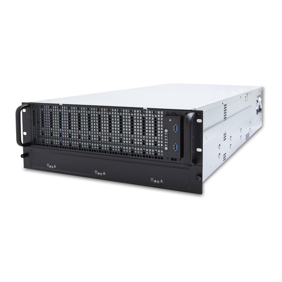
SB403-VG User Manual Chapter 1. Product Features SB403-VG is a high density storage storage server that includes a mother board, a chassis, power supply, fan, and HDD backplane. For more information about our product, please visit our website at http://www.aicipc.com/en. -
Page 11: Specifications
SB403-VG User Manual Chapter 1. Product Features 1.2 Specifications mm : 435 x 953 x 175.7 Insyde UEFI BIOS BIOS Type Dimensions (W x D x H) • ACPI • BIOS Boot inches : 17.1 x 37.5 x 6.9 • PXE... -
Page 12: 1�3 Features
Chapter 1. Product Features 1�3 Features SB403-VG is a reliable 4U storage server barebone with 60 hard drive disk bays that supports two Intel® Xeon® Scalable processors. This barebone consists of Intel® Lewisburg C620 series chipset, onboard baseboard management controller for system... - Page 13 SB403-VG User Manual Chapter 1. Product Features Front Panel SB403-VG provides 2 system buttons (Power & Reset) and 4 LED indicators (System power, LAN, System hard drive disk activity, Service ID). Power Button System Power LED LAN 1 LED LAN 2 LED...
- Page 14 SB403-VG User Manual Chapter 1. Product Features Rear Panel SB403-VG provides 3 LAN ports (10G SFP+ x 2, GbE RJ45 dedicated to BMC management), 2 USB 3.0 double stack Type A, 1 VGA port and 1 serial port.
- Page 15 SB403-VG User Manual Chapter 1. Product Features Major Components SB403-VG provides 1600W 1+1 redundant power supply 80+ Platinum and 4 hot swap fans (80 x 38mm) & 2 easy fans (60 x 38 mm).
-
Page 16: Chapter 2� Hardware Setup
Chapter 2� Hardware Setup SB403-VG User Manual Chapter 2. Hardware Setup This section describes a simple instruction guide for installing the hardware components on the serverboard system. Turn off and unplug all system and peripheral devices before proceeding. 2�1 Central Processing Unit Setup The serverboard supports dual Xeon scalable processors and Socket P0 (LGA-3647). - Page 17 SB403-VG User Manual Chapter 2. Hardware Setup Processor Socket Assembly: The server board includes two processor sockets (LGA-3647), supports one or two of the Intel® Xeon® Processor Scalable Family and has a Thermal Design Power (TDP) of up to 165W on selected models.
- Page 18 SB403-VG User Manual Chapter 2. Hardware Setup PHM Screw Installation Order: The PHM sits level with the processor socket assembly. The PHM is NOT installed properly if it does not sit level with the processor socket assembly. Once the PHM is seated over the processor socket assembly, the four heat sink torque screws must be secured in the following order as shown below.
-
Page 19: Cpu Heatsink
SB403-VG User Manual Chapter 2. Hardware Setup 2�1�4 CPU heatsink CAUTION There may be possible thermal during physical contact with the heatsink. Avoid moving the heatsink after it has contacted the top of the CPU. Too much movement could disturb the layer of thermal compound, causing voids and leading to ineffective heat dissipation and component damage. -
Page 20: 2�2 System Memory
SB403-VG User Manual Chapter 2. Hardware Setup 2�2 System Memory This server board supports up to twelve DDR4 2400 and 2666 Registered ECC DRAM/ Load-Reduced DIMM. JDIMML0 JDIMML0 JDIMMK0 JDIMMK0 JDIMMJ0 JDIMMJ0 JDIMMC0 JDIMMC0 JDIMMB0 JDIMMB0 JDIMMA0 JDIMMA0 CPU 1... -
Page 21: Dimm Installation Order
SB403-VG User Manual Chapter 2. Hardware Setup 2�2�1 DIMM Installation Order JDIMML0 JDIMMC0 JDIMMK0 JDIMMB0 JDIMMJ0 JDIMMA0 DIMM Numbers DIMM ARRANGMENT CPU 0 CPU 0 CPU 1 CPU 1 CPU1 CPU0 2 DIMMs JDIMM_L0 JDIMM_C0 JDIMMG0 JDIMMD0 JDIMMH0 JDIMME0 JDIMMI0... - Page 22 SB403-VG User Manual Chapter 2. Hardware Setup JDIMML0 JDIMMC0 JDIMMK0 JDIMMB0 JDIMMJ0 JDIMMA0 CPU1 CPU0 JDIMM_L0 JDIMM_C0 CPU 0 CPU 0 CPU 1 CPU 1 JDIMM_K0 JDIMM_B0 10 DIMMs JDIMM_J0 JDIMM_A0 JDIMM_G0 JDIMM_D0 JDIMMG0 JDIMMD0 JDIMM_I0 JDIMM_F0 JDIMMH0 JDIMME0 JDIMMI0...
-
Page 23: Dimm Installation
SB403-VG User Manual Chapter 2. Hardware Setup 2�2�2 DIMM Installation Step 1 Unlock the DIMM socket by pressing the retaining clips outward. Step 2 Insert the memory module into the slot. Make sure that the DIMM notch is accurately positioned. -
Page 24: 2�3 Removing And Installing The Top Cover
SB403-VG User Manual Chapter 2. Hardware Setup 2�3 Removing and Installing the Top Cover 2�3�1 Installing the top cover Position the top cover onto the chassis and push horizontally towards the adjacent top cover to install. 2�3�2 Removing the top cover Step 1 Press the release button on both sides of the chassis. -
Page 25: 2�4 Removing And Installing The Hard Disk Drive
SB403-VG User Manual Chapter 2. Hardware Setup 2�4 Removing and Installing the Hard Disk Drive 2�4�1 Installing the 3�5" hard disk tray Push the the hard drive disk tray into the chassis. 2�4�2 Removing the 3�5" hard disk drive tray Step 1 Place a finger inside the dent on the hard drive disk tray lever and pull upward. -
Page 26: Installing The 2.5" Hdd Tray Into The Chassis
SB403-VG User Manual Chapter 2. Hardware Setup 2�4�3 Installing the 2�5" HDD tray into the chassis Step 1 Insert the 2.5" HDD into the chassis until it clicks. Step 2 Close the tray lever. 2�4�4 Removing the 2�5" HDD tray out of the chassis Step 1 Push the release button on the tray lever. -
Page 27: Installing The Hard Disk Drive Into The Hard Disk Drive Tray
SB403-VG User Manual Chapter 2. Hardware Setup 2�4�5 Installing the hard disk drive into the hard disk drive tray Match the dimples on the tray to insert the HDD. Make certain that the HDD is not damaged during installation or removal process. -
Page 28: 2�5 Removing And Installing The Fan Module
SB403-VG User Manual Chapter 2. Hardware Setup 2�5 Removing and Installing the Fan Module 2�5�1 Installing/removing the fan Insert or pull the fan module to install or remove. Make certain to align the fan module to the appropriate slot. This information is provided for professional technicians only. -
Page 29: Installing/Removing The Fan From The Rear Panel
SB403-VG User Manual Chapter 2. Hardware Setup 2�5�2 Installing/removing the fan from the rear panel Secure or loosen the thumb screw x 1 on the fan module to install or remove. This information is provided for professional technicians only. -
Page 30: 2�6 Removing And Installing The Power Supply Unit Module
SB403-VG User Manual Chapter 2. Hardware Setup 2�6 Removing and Installing the Power Supply Unit Module 2�6�1 Installing the power supply Push the tray handle on the module to install. 2�6�2 Removing the power supply Step 1 Push the latch inward and hold the tray handle. -
Page 31: 2�7 Removing And Installing The Mother Board
SB403-VG User Manual Chapter 2. Hardware Setup 2�7 Removing and Installing the Mother Board 2�7�1 Installing the mother board Step 1 Push the mother board into the chassis. Step 2 Secure the screw x 8 pcs on both sides (screw x 4 pcs on each side of the chassis. -
Page 32: 2�8 Removing And Installing The Hdd Backplane Module
SB403-VG User Manual Chapter 2. Hardware Setup 2�8 Removing and Installing the HDD Backplane Module 2�8�1 Installing the HDD backplane Push the backplane module into the chassis and close the tray lever to install. 2�8�2 Removing the HDD backplane Step 1 Open the lever on the backplane. -
Page 33: 2�9 Removing And Installing The Tool-Less Blade Slide
SB403-VG User Manual Chapter 2. Hardware Setup 2�9 Removing and Installing the Tool-less Blade Slide 1. Pulling out the inner slide rail Step 1 Press the trigger downward to release the inner side rail. Step 2 Pull the inner rail out of the blade slide. - Page 34 SB403-VG User Manual Chapter 2. Hardware Setup 3. Installing the outer cabinet to the slide rail Insert the stag into the upper and lower square holes on rail from the back of rail. Push the safety lock forward to secure the bracket. Make certain to check if the safety lock is in disenaged position before mounting the brackets.
- Page 35 SB403-VG User Manual Chapter 2. Hardware Setup 4. Installing the chassis into the cabinet Insert the inner side of chassis into the cabinet. Check if the ball retainer is fully opened before installation. It may cause catastrophic damage to the chassis if ball retainer is not in fully open position while mounting the chassis.
-
Page 36: Chapter 3� Hardware Settings
Chapter 3� Hardware Settings SB403-VG User Manual Chapter 3.Hardware Settings This section describes the jumpers, internal connectors and internal LEDs settings. 3�1 Motherboard Block Diagram Platform Environment Control Interface(PECI) DIMM #H0 DIMM #J0 DIMM #L0 DIMM #B0 DIMM #D0 DIMM #F0... -
Page 37: 3�2 Motherboard Content List
Chapter 3.Hardware Settings SB403-VG User Manual 3�2 Motherboard Content List Connector/Jumper/Header Location Connector/Jumper/Header Location Power Supply JPWR1, JPWR3, Front I/O USB Header JUSB_INT Connector JPWR4 Power Supply JPWR2 SSI Front Panel Header JFRNT_SSI Connector External Thermal J2, J13, J24 NGFF Connector... -
Page 38: 3�3 Motherboard Layout
SB403-VG User Manual Chapter 3.Hardware Settings 3�3 Motherboard Layout CPU1 CPU1 CPU0 CPU0 CPU0 19 18... -
Page 39: 3�4 Connector And Jumper
Chapter 3.Hardware Settings SB403-VG User Manual 3�4 Connector and Jumper 3�4�1 Connector 6 SAS IOC Activity LED Header (J19) Power Connector (JPWR1, JPWR3 & JPWR4) +3.3V SAS_LED_GPIO16 SAS_LED_GPIO20 SAS_LED_GPIO17 SAS_LED_GPIO21 SAS_LED_GPIO18 SAS_LED_GPIO22 SAS_LED_GPIO19 SAS_LED_GPIO23 7 SAS IOC Error LED Header (J25) 2 Power Connector (JPWR2) +3.3V... - Page 40 SB403-VG User Manual Chapter 3.Hardware Settings SFF-8643 Connector for PCIe (CN1) SFF-8643 Connector for PCIe (CN4) SMBDAT_MUX_6 C1 A1 CLK_100M_SSD6_P SMBDAT_MUX_4 C1 A1 CLK_100M_SSD4_P SMBCLK_MUX_6 C2 A2 CLK_100M_SSD6_N SMBCLK_MUX_4 C2 A2 CLK_100M_SSD4_N C3 A3 GND C3 A3 GND CPU1_EXP1_TX_DP_13 C4 A4 CPU1_EXP1_RX_DP_13...
- Page 41 Chapter 3.Hardware Settings SB403-VG User Manual SFF-8643 connector for SAS (CN7) SIO1_SAS_DOUT C1 A1 N.C. C2 A2 SIO1_SAS_CLK C3 A3 GND SAS_EXP_TX_P6 C4 A4 SAS_EXP_RX_P6 SAS_EXP_TX_N6 C5 A5 SAS_EXP_RX_N6 C6 A6 GND SAS_EXP_TX_P7 C7 A7 SAS_EXP_RX_P7 SAS_EXP_TX_N7 C8 A8 SAS_EXP_RX_N7...
- Page 42 SB403-VG User Manual Chapter 3.Hardware Settings 15 PCH SSGPIO Header (JSSGPIO) 27 Front I/O USB Header (JUSB_INT) 17 PCH GPIO Header (JPCH_GPIO) 28 SSI Front Panel Header (JFRNT_SSI) 24 SAS IOC ICE Header (J12)
- Page 43 Chapter 3.Hardware Settings SB403-VG User Manual 32 EPSI Header (JEPSI) 34 PCIE Hot-Plug SMB Header (JPCIE_HP) 33 Debug Port Header (JLPC_DP) 35 PCIE Hot-Plug Front Panel Header (J4, J5, & J6)
- Page 44 SB403-VG User Manual Chapter 3.Hardware Settings 38 Front COM Header (JCOM1 & JCOM4) 42 BMC Debug Port Header (JBMC_DP) 39 VROC KEY Header (JRAID_KEY) 44 BMC I2C1 header (JBMC_I2C1) I2C1SCL I2C1SDA 40 LCM Header (JLCM) 45 BMC GPIO header (JBMC_GPIO)
-
Page 45: Jumper
Chapter 3.Hardware Settings SB403-VG User Manual 3�4�2 Jumper 26 No Reboot(Watch Dog) Jumper (J26) SATA4 Pin-7 Power Header (J10) J26 (No Reboot) Setting Setting Short SATA4 pin-7 Power Short Enable Open Normal Default Open Disable Default 36 ME Force Recovery Mode Jumper (J3) -
Page 46: 3�5 Leds
SB403-VG User Manual Chapter 3.Hardware Settings 3�5 LEDs 3.5.1 Front Panel LED Definition Yellow The system is On. The system is in Standby; System is off, but Power Blinking has AC power. System has no AC power Blue UID activity is detected. -
Page 47: Internal Led
Chapter 3.Hardware Settings SB403-VG User Manual 3�5�3 Internal LED LAN2 10G LED LAN1 10G LED SFP+ LAN1 1G LED LAN2 1G LED LAN4 1G/10G LED LAN3 1G/10G LED BMC Heart Beat LED SAS IOC Status LED NVME Hot-Plug LED (PHY0~PHY7) -
Page 48: 3�6 Hdd Backplane: 2 Bay
SB403-VG User Manual Chapter 3.Hardware Settings 3�6 HDD Backplane: 2 Bay 3�6�1 Placement: 2 Bay SATA port x 4 HDD x 2... -
Page 49: Connector Location: 2 Bay Backplane
Chapter 3.Hardware Settings SB403-VG User Manual 3�6�2 Connector Location: 2 Bay Backplane Power (JP1 ) LED I/O (J3,J7) Fail LED (-) LED (+) 4V3 Fail in ACC LED (-) ACC LED input... -
Page 50: 3�7 Hdd Backplane: 20 Bay
SB403-VG User Manual Chapter 3.Hardware Settings 3�7 HDD Backplane: 20 Bay 3�7�1 Placement: 20 Bay HDD14 HDD13 HDD8 HDD7 HDD16 HDD15 HDD5 HDD6 HDD17 HDD18 HDD12 HDD4 HDD19 HDD20 HDD9 HDD2 HDD1 HDD3 HDD10 HDD11... -
Page 51: Connector Location: 20 Bay Backplane
Chapter 3.Hardware Settings SB403-VG User Manual 3�7�2 Connector Location: 20 Bay Backplane Front Plane Control Connector- Fault LED UART–JUART1 JREAR, JFRONT connector-J1 11 12 RS232_SDB_TX RS232_UART_TX BUZZER_MUTE_GND FAULT_LED BUZZER_MUTE_N PSU_FAIL_LED_VCC +3V3 PSU_FAIL_LED_N RS232_UART_RX RS232_SDB_RX FAN_FAIL_LED_N FAN_FAIL_LED_VCC TEMP_ERR_LED_VCC TEMP_ERR_LED_N ENCLOSURE_LED_N ENCLOSURE_LED_VCC... -
Page 52: Leds
SB403-VG User Manual Chapter 3.Hardware Settings 3�7�3 LEDs LED Definition Blue (On) HDD present Blue (Blinking) HDD activity detected or Locate HDD HDD Activity LEDs HDD no connect or p ower Off Normal Red (Blinking) Re-build status for RAID HDD Fault LEDs... -
Page 53: Chapter 4. Bios Configuration Settings
Chapter 4. BIOS Configuration Settings Chapter 4 BIOS Configuration Settings SB403-VG User Manual This chapter demonstrates how to configure the UEFI BIOS settings in your system device. You can enter the BIOS screen during system startup. To enter BIOS configuration settings, •... -
Page 54: 4�2 Bios Menu
SB403-VG User Manual Chapter 4 BIOS Configuration Settings 4�2 BIOS Menu Press and to select the options of the menu bar. Press Enter to access the option screen. Menu Description Main Displays basic system information and date & time. -
Page 55: 4�3 Main
Chapter 4 BIOS Configuration Settings SB403-VG User Manual 4�3 Main Main Option Key: 4�3�1 Main Main System time Configures the current time. System date Configures the current date. -
Page 56: 4�4 Advanced
SB403-VG User Manual Chapter 4 BIOS Configuration Settings 4�4 Advanced Advanced Option Key: 4.4.1 Peripheral Configuration Peripheral Configuration PCIe SR-IOV [Enable] Disable PCIe ARI Enable [Disable] ARI Forward Enable [Disable] Spread Spectrum Enable [Disable] 4.4.2 Video Configuration Video Configuration Display Mode... -
Page 57: Sio Ast2500
Chapter 4 BIOS Configuration Settings SB403-VG User Manual 4�4�4 SIO AST2500 SIO AST2500 Serial Port A Auto [Enable] Disable Base I/O Address [3F8] Interrupt IRQ3 [IRQ4] Serial Port B Auto [Enable] Disable Base I/O Address [2F8] Interrupt [IRQ3] IRQ4 Serial Port D... - Page 58 SB403-VG User Manual Chapter 4 BIOS Configuration Settings Volatile Memory [Auto] Mode AppDirect cache Auto Enable [Disable] eADR Support Auto Enable [Disable] 1LM Memory 256B Target, 64B Target, 64B Interleave [Auto] 256B Channel Channel Granularity Memory Map IMC Interleaving [Auto]...
- Page 59 Chapter 4 BIOS Configuration Settings SB403-VG User Manual App Direct [Enable] Disable Memory Hole SWSMI [ASL] implementation SMBus Max Min= 0, Max= 4294967295, [350] Access Time NGNVM DIMM NGN Configuration Secure Erase SMBus Release Min= 0, Max= 4294967295, [150] Unit...
- Page 60 SB403-VG User Manual Chapter 4 BIOS Configuration Settings PCI 64-Bit Resource [Enable] Disable Allocation PCIe Train by BIOS [Yes] PCIe Hot Plug Auto Manual Enable [Disable] PCIe ACPI Hot Plug Enable [Disable] Per-Port PCI-E Completion Timeout (Global) [No] Per-Port Disable...
- Page 61 Chapter 4 BIOS Configuration Settings SB403-VG User Manual Intel® VMD 32-bit non-prefetchable for Volume [64-bit non-prefetchable] Intel® VMD MemBar2 IIO Configuration Management technology attribute Device on 64-bit prefetchable Socket 0 WFR Uncore GV Auto Enable [Disable] Rate Reduction Uncore Freq...
- Page 62 SB403-VG User Manual Chapter 4 BIOS Configuration Settings Non-Snoop Latency Min=0, Max=7, [0] Latency Multiplier Tolerence Requirement Non-Snoop Min=0x0, Max=0x3ff Latency Value IIO0_PKGC_ Enable CLK_GATE_ [Disable] DISABLE IIO1_PKGC_ Enable CLK_GATE_ [Disable] DISABLE IIO2_PKGC_ Enable CLK_GATE_ [Disable] DISABLE UPI01_PKGC_ Enable CLK_GATE_...
-
Page 63: Me Configuration
Chapter 4 BIOS Configuration Settings SB403-VG User Manual 4.4.6 ME Configuration ME Configuration Altitude Min=0x0, Max=0xffff, [0x8000] Server ME General ME Configuration Configuration MCTP Bus Owner Min=0x0, Max=0xffff, [0x0] ME Initialization Min=0, Max=12, [2] Complete Timeout Enable HSIO [Enable] Disable... -
Page 64: Pch Configuration
SB403-VG User Manual Chapter 4 BIOS Configuration Settings 4.4.7 PCH Configuration PCH Configuration PCH Devices PCH state after G3 [S5] Last State SATA Controller [Enable] Disable Configure SATA as [AHCI] RAID Support Aggressive Link Power [Enable] Disable Management Port 0~7... -
Page 65: H2O Ipmi Configuration
Chapter 4 BIOS Configuration Settings SB403-VG User Manual 4.4.8 H2O IPMI Configuration H2O IPMI Configuration IPMI Support [Enable] Disable BMC Warmup Time Min=0, Max=240, [90] ACPI SPMI Table [Enable] Disable Boot Option Support [Enable] Disable Set BIOS version to [Enable]... -
Page 66: H2O Event Log Config Manager
SB403-VG User Manual Chapter 4 BIOS Configuration Settings 4.4.11 H2O Event Log Config Manager H2O Event Log Config Manager BIOS Log Event To BIOS Event Log BIOS Event [BMC SEL] Memory Disable Configuration Log Viewer Event Log [Stop Overwrite Clear All... -
Page 67: 4�5 Security
Chapter 4 BIOS Configuration Settings SB403-VG User Manual 4�5 Security Security Option Key: 4�5�1 Security Security Current TPM Device Not Detected TPM 1.2 [TPM 2.0] TPM Active PCR Hash [SHA1, SHA256] Algorithm TPM Hardware Supported Hash [SHA1, SHA256] Algorithm TrEE Protocol Version 1.0 [1.1]... -
Page 68: 4�6 Power
SB403-VG User Manual Chapter 4 BIOS Configuration Settings 4�6 Power Power Option Key: 4�6�1 Power Power Wake on PME Enable [Disable]... -
Page 69: 4�7 Boot
Chapter 4 BIOS Configuration Settings SB403-VG User Manual 4�7 Boot Boot Option Key: 4�7�1 Boot Boot Boot Type [Dual Boot Type] Legacy Boot Type UEFI Boot Type Quick Boot [Enable] Disable Quiet Boot Enable [Disable] Network Stack [Enable] Disable [Disable]... -
Page 70: 4�8 Exit
SB403-VG User Manual Chapter 4 BIOS Configuration Settings 4�8 Exit Exit Option Key: 4�8�1 Exit Save and Exit Exit Saving Changes Exit system setup and save your changes. Save Change Without Exit Save your changes without exiting the system. Exit Discarding Changes Discard your changes when existing the system. -
Page 71: Chapter 5. Bmc Configuration Settings
Chapter 5. BMC Configuration Settings SB403-VG User Manual Chapter 5. BMC Configuration Settings Plugging the Ethernet LAN cable into the BMC LAN port. There are two methods to setup BMC IP: BMC management port 5�1 Method 1 (Use the BIOS Setup) 1. - Page 72 SB403-VG User Manual Chapter 5. BMC Configuration Settings...
- Page 73 SB403-VG User Manual Chapter 5. BMC Configuration Settings 3. Input the subnet mask address.
-
Page 74: 5�2 Method 2 (Use A Dos Tool - Syscheck)
SB403-VG User Manual Chapter 5. BMC Configuration Settings 5�2 Method 2 (Use a Dos Tool - Syscheck) 1. Type in "sc –lanset." 2. Modify the IP setting. NOTE Type 1 for selecting static IP mode or Type 2 for selecting DHCP mode. - Page 75 SB403-VG User Manual Chapter 5. BMC Configuration Settings 4. Input the submask address. The IP address below is an example using a default IP setting. Users are allowed to change the IP address for realistic use. 5. Finish the BMC IP configuration.
-
Page 76: 5�3 Connect To Bmc
SB403-VG User Manual Chapter 5. BMC Configuration Settings 5�3 Connect to BMC This feature works with JAVA 6 Runtime installed Console Environment. The IP address below is an example using the default IP setting. The IP address is configurable. 1. Open the browser and type in the default BMC IP address: 192.168.22.22 2. - Page 77 SB403-VG User Manual Chapter 5. BMC Configuration Settings 3. Dashboard: 4. Sensor Readings: 5. Settings: Refer to AIC BMC User Guide for more information on AIC BMC.
- Page 78 SB403-VG User Manual Chapter 5. BMC Configuration Settings Mouse Mode setting: • For Windows OS environment, set mode to absolute. • For Linux OS environment, set mode to relative. • For SLES-11 OS environment, set mode to other modes. 6. Remote Control:...
- Page 79 SB403-VG User Manual Chapter 5. BMC Configuration Settings Environmental setting:...
-
Page 80: 5�4 Updating Bmc Firmware
A:>cd SB301C01 A:\ SB301C01>a.bat This is just an example. The latest BMC firmware version is available from the FAE or AIC website. 4. After updating BMC firmware, turn the power off and reset the system. NOTE 1. Do not EM386 in DOS Environmnet when updating firmware or you will recieve a failure 2. -
Page 81: Chapter 6� Technical Support
Chapter 6� Technical Support Taiwain, Global Headquarters South California, United States Address: No� 152, Section 4, Address: 21808 Garcia Lane Linghang N� Rd, Dayuan District, City of Industry, CA 91789, Taoyuan City 337, Taiwan United States Tel: +886-3-433-9188 Toll free: +7-4997019998 Fax: +886-3-287-1818 Tel: +1-909-895-8989 Fax: +1-909-895-8989#157...
Need help?
Do you have a question about the SB403-VG and is the answer not in the manual?
Questions and answers