Table of Contents
Advertisement
Quick Links
Advertisement
Table of Contents

Related Manuals for AIC HP201-AG


Summary of Contents for AIC HP201-AG
- Page 1 HP201-AG Storage Barebone User's Manual UM_HP201-AG_v1_082021...
-
Page 2: Table Of Contents
Table of Contents Preface ������������������������������������������������������������������������������������������������ i Safety Instructions ������������������������������������������������������������������������������ ii About This Manual ����������������������������������������������������������������������������� iv Chapter 1� Product Features �������������������������������������������������������������� 1 1.1 Box Contents .................... 1 1.2 Specifications .................... 2 1.3 System Block Diagram ................3 1.4 Feature ....................... 4 Chapter 2�... - Page 3 Chapter 4� BIOS Configuration Settings ������������������������������������������� 38 4.1 Navigation Keys ..................38 4.2 Menu ....................... 39 4.3 Main ......................40 4.4 Advanced ....................41 4.4.1 Trusted Computing ....................41 4.4.2 ACPI Settings ...................... 41 4.4.3 AMD PBS ......................42 4.4.4 AMD CBS ......................42 4.4.5 Serial Port Console Redirection ................49 4.4.6 CPU Configuration ....................
- Page 4 Document Release History Release Date Version Update Content August, 2021 User's Manual release to public.
- Page 5 Copyright © 2021 AIC®, Inc� All Rights Reserved� This document contains proprietary information about AIC® products and is not to be disclosed or used except in accordance with applicable agreements.
-
Page 6: Preface
Disclaimer AIC® shall not be liable for technical or editorial errors or omissions contained herein. The information provided is provided "as is" without warranty of any kind. To the extent permitted by law, neither AIC®... -
Page 7: Safety Instructions
Safety Instructions Before you commence, please attentively read the following important discretions below. All cautions and warnings on the equipment or in the manuals should be circumspectly noted and reviewed. Always ground yourself to prevent static electricity. Always ground yourself to prevent static electricity. 請... - Page 8 • Ensure that the voltage of the power source is within the specification on the label when connecting the equipment to the power outlet. The current load and output power of loads must be within the specification. • This equipment must be firmly connected to reliable grounding before usage. Pay special attention to power supplied other than direct connections, e.g.
-
Page 9: About This Manual
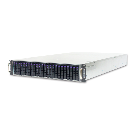
Chapter 1 Product Features HP201-AG is a flexible 2U 4 node hyper-converged server that supports 24 hot swap 2.5- inch drives bays for NVMe SSDs(U.2)/SATA/SAS. With the maximization of the memory capacity and add-on card installation, this server is specifically designed to accommodate diverse corporations and enterprises for managing heavy workloads and multiple applications. -
Page 10: Chapter 1� Product Features
Chapter 1� Product Features HP201-AG is a high density storage server that includes motherboard, chassis, power sup- ply and disk drives. For more information about our product, please visit our website at https://www.aicipc.com/en/index. Before removing the subsystem from the shipping carton, visually inspect the physical condition of the shipping carton. -
Page 11: Specifications
Processor • PXE (support by EPYC™ 7003 CPU) Processor Support • IPMI KCS interface System BIOS *Please contact AIC Technical Support for (per node) • SMBIOS more info/details about optimized CPUs and BIOS Features • SRIOV specialized system. • iSCSI •... -
Page 12: System Block Diagram
Chapter 1. Product Features 1�3 System Block Diagram... -
Page 13: Feature
Chapter 1. Product Features 1�4 Feature HP201-AG is a reliable 2U 4 node hybrid storage server barebone with 24 * 2.5-inch hot- swap drives bays. This product is designed to accommodate the AIC® patented server- board, Auriga, which supports one AMD EPYC™ 7000-series processor and 8 DDR4 2400/2666 DIMM to offer greater perfomance, efficiency and utility for our customers. - Page 14 Chapter 1. Product Features Front Panel Item Description Item Description Node Power Button Node ID LED Node Power Status LED BMC Alert LED Node Control Panel Corresponding Control Drive Rear Panel Item Content Description 1600W 1+1 redundant power supply 80+ Platinum •...
- Page 15 Node Top View Item Content Description 4 * 60x56mm easy swap fans 60x38m easy swap fan Disk Drive 2.5-inch disk drive (optional) Server board AIC® Auriga Riser Card PCIex16...
-
Page 16: Chapter 2� Hardware Setup
Chapter 2� Hardware Setup This section describes a simple instruction guide for installing the hardware components on the serverboard system. Turn off and unplug all system and peripheral devices before proceeding. 2�1 Central Processing Unit The serverboard supports a single AMD EPYC™ 7000-series and socket type SP3. 2�1�1 Processor Installation To ensure a safe and easy setup, you need to prepare before installation: ... - Page 17 Chapter 2. Hardware Setup Lift the carrier frame by the blue metal tab and remove the protective cover as demonstrated in figure 3 and figure 4. Lift carrier frame Remove protective cover Front Front Insert the CPU package into the carrier frame as demonstrated in figure 5. Insert package Front ...
- Page 18 Chapter 2. Hardware Setup Close the carrier frame with the CPU package as demonstated in figure 7. Check if the frame is properly installed as demonstrated in figure 8. Close carrier frame Verify installation Front Front Close the load plate and fasten the screws in the order 123 to complete installation as demonstrated in figure 9.
-
Page 19: System Memory
Chapter 2. Hardware Setup 2�2 System Memory 2�2�1 DIMM Placement The DIMMs are displayed on the Auriga board as JDMA0, JDMB0, JDMC0, JDMD0, JDME0, JDMF0, JDMG0, JDMH0 as demonstrated. JDMA0 and JDME0 are the located nearest to the CPU. To ensure satisfactory performance, you need to: ... -
Page 20: Installation
Chapter 2. Hardware Setup 2�2�3 Installation Unlock the DIMM socket by pressing the retaining clips outward. Insert the memory module into the slot. Make sure that the DIMM notch is accurately positioned. DIMM notch Close the retaining clips to complete installation. ... -
Page 21: Top Cover
Chapter 2. Hardware Setup 2�3 Top Cover Push the cover toward the rear panel. Lift the top cover upward to remove. This information is provided for professional technicians only. -
Page 22: Power Supply Unit
Chapter 2. Hardware Setup 2�4 Power Supply Unit 2�4�1 Installation Press the ejector to release the module. Pull the handle to remove the module out of the chassis. Push the replaced power supply unit into the chassis. Ensure that the module is hooked into the cage. -
Page 23: Fan
Chapter 2. Hardware Setup 2�5 Fan Remove the top cover from the chassis. Please refer to Section 2.3 Top Cover. Unplug the cables and connectors from the server board. Pull the fan out of the chassis. Insert the replaced fan into the chassis. Verify the alignment of the rubber connectors of the fan and the bracket. -
Page 24: Disk Drive
Chapter 2. Hardware Setup 2�6 Disk Drive 2�6�1 External Disk Drive Press the ejector on the tray to release the handle. Pull the tray handle completely outward. Pull the drive tray out of the chassis. ... -
Page 25: Internal Disk Drive
Chapter 2. Hardware Setup 2�6�2 Internal Disk Drive Remove the top cover from the chassis. Please refer to Section 2.3 Top Cover. Lift and slightly rotate the 2.5-inch drive cage out of the chassis. Press the ejector on the drive tray to release the handle. ... -
Page 26: Led Indicator
Chapter 2. Hardware Setup 2�6�3 LED Indicator Indicator Behavior Description Solid NVMe/SATA/SAS drive is in idle state. Blinking Blue NVMe/SATA/SAS is active. (4Hz) NVMe/SATA/SAS is not detected or the system power is off. Blinking Green NVMe/SATA/SAS is in locate status. (4Hz) Solid There is a drive fault. -
Page 27: Node
To implement the riser card To implement the riser card (top view) (R) into your system, please (R) into your system, please contact AIC® FAE for more contact AIC® FAE for more information. information. This information is provided for professional technicians only. -
Page 28: Air Duct
Chapter 2. Hardware Setup 2�9 Air Duct Pull the node from the chassis. Please refer to Section 2.7 Node. Dislodge the screws and lift the air duct upward to remove. Air duct placement (top view) CAUTION Please check the placement of the air duct in the manual before installation to prevent damage to the system. -
Page 29: Slide Rail
Chapter 2. Hardware Setup 2�10 Slide Rail NOTE This sections provides a basic instruction for mounting the slide rail onto the system. Tool-less rails vary per order. The rail in this manual may not exactly match the rail for your system. Please refer to the spefications or quick installation guide that came with your purchased product. - Page 30 Chapter 2. Hardware Setup 4. Install the inner rail onto the system barebone. Lock the keyholes and secure the system with M4*4L screws. Keyhole Screw 5. Continue installing the outer rail bracket to the mounting frame. Attach the outer rail assembling to the frame and press the bracket to form a rack on both ends.
- Page 31 Chapter 2. Hardware Setup 6. Pull out the middle channel until the ball bearing retainer is locked forward. NOTE Verify ball bearing retainer is locked forward. 7. Slide the release tab and push barebone into rack. Make sure the barebone is completely installed onto the rack.
-
Page 32: Chapter 3� Hardware Settings
Chapter 3� Hardware Settings This section provides illustrations that display the internal jumpers, connectors and system LED indicators on the Auriga motherboard. The motherboard layout and essential connectors are listed below for your reference. 3�1 Motherboard 3�1�1 Block Diagram... -
Page 33: Content List
Chapter 3. Hardware Settings 3�1�2 Content List Connector/Jumper/Header Placement Connector/Jumper/Header Placement JG0FR1 JG0FR2 JG1FR1 PCIe Bus SAS slimline JG1FR2 Battery Socket JBAT1 Connector JG2FL1 (For CR2032) JG2FL2 JG3FL1 JG3FL2 JFAN1 JFAN2 Fan Header 22 SOC CMOS Clear Jumper JCMOS1 JFAN3 JFAN4 JPCIE1 3 HDT Connector... -
Page 34: Connector And Junper Placement
Chapter 3. Hardware Settings 3�1�3 Connector and Junper Placement 1g 1e 2a2b 2c 2d 4a 1d 1b CPU0... -
Page 35: 3.1.4 Connector And Junper Pin Define
Chapter 3. Hardware Settings 3.1.4 Connector and Junper Pin Define 2a Fan Header (JFAN1) FANTACH_2 2 FANTACH_1 +12V_S0 3 4 +12V_S0 2x4-pin header that connects SYS1_FAN_PWM_C 5 6 SYS1_FAN_PWM_C fan 1. GND 7 8 GND 2b Fan Header (JFAN2) FANTACH_4 2 FANTACH_3 2x4-pin header that connects +12V_S0 3... - Page 36 Chapter 3. Hardware Settings 6 Power Supply Connector (JPWR1) +12V_S0 8 +12V_S0 9 2 GND 2x7-pin connector for main power supply. +12V_S0 10 3 GND +12V_S0 11 4 GND +12V_S0 12 5 GND +5V_STBY_PSU 13 6 GND PS_OK_12V 14 7 PS_ON_12V_N 12a SATA - DOM Power Jumper (JSATA1_PWR1) +5V_S0_SATA1 2 GND...
- Page 37 Chapter 3. Hardware Settings 16 LPC Debug Port Header (JLPC1) LPC_HDR_CLK 2 P0_LFRAME_N 4 3 P0_LDRQ0_N 2x6-pin header for low pin count debug. LPC_HDR_RST_N 6 5 P0_SERIRQ P0_LAD3 8 7 P0_LAD2 +3V3_S0 10 9 P0_LAD1 P0_LAD0 12 11 GND +5V_HUB2 2 +5V_HUB2 7 Front I/O USB Header (JUSB_INT1) USB2_HUB1_DN 3...
- Page 38 Chapter 3. Hardware Settings 29a BMC Console Port Select Header (J3) 2 PJ_TX 3-pin header for selecting BMC console. 3 TX5 Jumper default Pin-1 & Pin-2 29b BMC Console Port Select Header (J4) 3-pin header for selecting 2 PJ_RX BMC console. 3 RX5 Jumper default Pin-1 &...
- Page 39 Chapter 3. Hardware Settings 38 BMC COM2 Header (JCOM1) 2x5-pin COM2 header for BMC. DCDB 2 1 DSRB RXDB 4 3 RTSB TXDB 6 5 CTSB DTRB 8 7 RIB GND 10 9 NC 39 GPIO Header (JBMC_GPIO1) RACK_EXTRST_N 2 1 GND 2x3-pin GPIO BMC header.
-
Page 40: Internal Led
Chapter 3. Hardware Settings 3�1�5 Internal LED LED1 LED1 LED2 LED9 LED3 LED4 LED5 LED7 LED6 JLAN1 Pin-13, 14 LED 8 Pin-15, 16... - Page 41 Chapter 3. Hardware Settings JSATA1 status On (Blinking) Indicates SATA is in use when LED is lit. LED1 Indicates SATA is un-used when LED is dark. (U2005 ASM1061) JSATA2 status On (Blinking) Indicates SATA is in use when LED is lit. LED2 Indicates SATA is un-used when LED is dark.
-
Page 42: Rear I/O Panel
Chapter 3. Hardware Settings 3�1�6 Rear I/O Panel Item Placement Item Placement LAN RJ45 Port VGA port COM port by 3.5mm phone jack USB 2.0/3.0 Port *2 LAN LED Activity/Link Speed Item Color Behavior No link. Activity/Link LED Yellow (blinking) Data activity. -
Page 43: Sas/U.2 Drive Backplane
Chapter 3. Hardware Settings 3�2 SAS/U�2 Drive Backplane 3�2�1 Placement Top View CN_PWR_D1 JPWR4 JPWR2 JSENSOR1 JFAN4 JFAN3 JFAN2 JFAN1 JIPMB_I2C JI2C_PMBUS CN_PWR_B1 JFAN_OS1 JPSON1 JFRNT3 JFRNT2 JPWR_CD1 JPWR_AB1 JPWR3 JPWR1 CN_PWR_A1 JPDB_1 JSLIM_CD1 JSLIM_AB1 CN_PWR_C1 Bottom View 3�2�2 Connector and Jumper Power Input Connector (JPWR1, JPWR2, JPWR3, JPWR4) +12V 6 1 GND... - Page 44 Chapter 3. Hardware Settings OS Fan Connector (JFAN_OS1) OS_FAN_TACH1 1 2 OS_FAN_TACH2 +12V 3 4 +12V OS_PWM 5 6 GND Thermal Sensor Connector (JSENSOR) 1 DP 2 DN IPMB External Connector (JIPMB_I2C) 1 IPMB_SCL 2 GND 3 IPMB_SDA PMBUS External Connector (JI2C_PMBUS) 1 BMC_I2C6_SCL 2 GND 3 BMC_I2C6_SDA...
- Page 45 Chapter 3. Hardware Settings PDB Function I/F (JPDB_1) BMC_I2C6_SCL 2 1 PSU_PON BMC_I2C6_SDA 4 3 POWER_OK PSU_PRSENT_1 6 5 PMBUS_ALERT PSU_PRSENT_2 8 7 GND +12VSTBY 10 9 GND +12VSTBY 12 11 GND +12VSTBY 14 13 GND PS_ON Mode Selection (JPSON1) POWER_ON PSU_PON ATX Mode...
-
Page 46: Cable Routing
Chapter 3. Hardware Settings 3�2�3 Cable Routing Top view Connects to SATA/U.2 storage device Bottom view Connects four 10-pin plug from motherboard Connects the data cable to motherboard... -
Page 47: Chapter 4� Bios Configuration Settings
BIOS update. The BIOS menu provided are the most updated ones when this manual is written. NOTE For further details about the BIOS, please refer to BIOS section in the Auriga manual for reference. AIC® website link: https://www.aicipc.com/en/productdetail/50929. 4�1 Navigation Keys The navigation keys are listed below. Function Key Description <... -
Page 48: Menu
Chapter 4. BIOS Configuration Settings 4�2 Menu Press and to select the options of the menu bar. Press Enter to access the option screen. Menu Description Displays system information such as CPU bus speed, system memory Main speed, total installed memory, current EFI language, and system date & time. -
Page 49: Main
Chapter 4. BIOS Configuration Settings 4�3 Main Main System Configures the language used in the system. Language System time Configures the current time. System date Configures the current date. -
Page 50: Advanced
Chapter 4. BIOS Configuration Settings 4�4 Advanced 4�4�1 Trusted Computing Trusted Computing settings. Trusted Computing Security Device Enable Disable Support SHA-1/256/384 Enable Disable PCR Bank Pending opertation None TPM Clear Platform Hierarchy Enable Disable Storage Hierarchy Enable Disable Endorsement Enable Disable Hierarchy TPM 2.0 UEFI Spec... -
Page 51: Amd Pbs
Chapter 4. BIOS Configuration Settings 4�4�3 AMD PBS AMD PBS setup page. AMD PBS RAS Periodic SMI Enable Disable Control SMI Threshold SMI Scale 1000 SMI Scale Unit millisecond second minute SMI Period 1000 GHES Notify Type Polled GHES UnCorr Notify Polled Type PCIe GHES Notify... - Page 52 Chapter 4. BIOS Configuration Settings Platform First Error Auto Enable Disable Handling Core Performance Auto Enable Disable Boost Global C-state Auto Enable Disable Control Power Supply Idle Auto Low Current Idle Typical Current Idle Control SEV ASID Count Auto 253 ASIDs 509 ASIDs SEV-ES ASID Space Auto...
- Page 53 Chapter 4. BIOS Configuration Settings ACPI SRAT L3 Cache As Auto Enable Disable NUMA Domain ACPI SLIT ACPI Distance Auto Manual Control ACPI SLIT remote relative Auto Near distance GMI encryption Auto Enable Disable control xGMI encryption Auto Enable Disable control CAKE CRC perf Auto...
- Page 54 Chapter 4. BIOS Configuration Settings 7.8 usec DRAM Refresh Rate 3.9 usec DRAM Power Trfc / 3 Options Self-Refresh Trfc / 4 Exit Staggering Disable DRAM Cmd2T Auto Controller Gear Down Configuration Auto Enable Disable Mode CAD Bus Timin Auto Manual User Controls CAD Bus Drive...
- Page 55 Chapter 4. BIOS Configuration Settings Address Hash Auto Enable Disable DRAM Memory Address Hash Auto Enable Disable Mapping SPD Read Auto Enable Disable Optimization Disable NVDIMM NVDIMM-N Feature MBIST Enable Enable Disable Pattern Select PRBS Both Pattern Length 3 1 Agressor 3 Agressor Channel Channels...
- Page 56 Chapter 4. BIOS Configuration Settings CPPC Auto Enable Disable HSMP Support Auto Enable Disable DLWM Support Auto Enable Disable Boost Fmax En Auto Manual EDC Current Enable Disable Tracking SMU Common Options Root Complex LCLK 0x00/0x40/ Frequency 0x80/0xC0 Auto 593Mhz Control LCLK Frequency...
- Page 57 Chapter 4. BIOS Configuration Settings CV test Auto Enable Disable NBIO Common Options SEV-SNP Support Enable Disable SATA Enable Auto Enable Disable Sata RAS Auto Enable Disable Support Sata Disabled AHCI Prefetch Auto Enable Disable Function Aggresive SATA Configuration SATA Device Auto Enable Disable...
-
Page 58: Serial Port Console Redirection
Chapter 4. BIOS Configuration Settings 4�4�5 Serial Port Console Redirection Serial Port Console Redirection. Serial Port Console Redirection Console Redirection Enable Disable Terminal Type ANSI VT100 VT100+ VT-UTF8 Bits per second 9600 19200 38400 57600 115200 Data Bits Parity Even Mark Space None... -
Page 59: Pci Subsystem Settings
Chapter 4. BIOS Configuration Settings 4�4�10 PCI Subsystem Settings PCI Subsystem settings. PCI Subsystem Settings Enable Disable Above 4G Decoding Enable Disable SR-IOV Support Enable Disable BME DMA Mitigation Enable Disable Enable Disable Hot-Plug Support Enable Disable Disable Above 4G Enable Disable Onboard Device... -
Page 60: 4.4.14 T1S Auth Configuration
Chapter 4. BIOS Configuration Settings 4.4.14 T1s Auth Configuration Select T1s Auth Configuration. T1s Auth Configuration Enroll Cert Using File Enroll Cert using file. Enroll Cert Commit Changes and Exit Commit changes and exit. Server CA Configuration Discard Changes and Exit Discard changes and exit. -
Page 61: Chipset
Chapter 4. BIOS Configuration Settings 4�5 Chipset Chipset PCIe Link Training 1 step 2 step PCIe Compliance Mode... -
Page 62: Security
Chapter 4. BIOS Configuration Settings 4�6 Security Security Administrator Set administer password. Password Set User Password Create new password. Secure boot configuration. Secure Boot Secure Boot Enable Disable Secure Boot Mode Standard Custom... -
Page 63: Boot
Chapter 4. BIOS Configuration Settings 4�7 Boot Boot Set Prompt Timeout 1 Bootup Numlock State Quiet Boot Enable Disable UEFI: Built-in EFI Shell Disable Boot Option #1/2 UEFI: Built-in EFI Shell Disable... -
Page 64: Save And Exit
Chapter 4. BIOS Configuration Settings 4�8 Save and Exit Save and Exit Save Change and Exits system setup after saving the changes. Exit Discard Changes Exits system setup without saving any changes. and Exit Save Changes and Resets the system after saving the changes. Reset Discard Changes Resets system setup without saving any changes. -
Page 65: Event Logs
Chapter 4. BIOS Configuration Settings 4�9 Event Logs 4�9�1 Change Smbios Event Log Settings Configures Smbios event log. Event Logs Smbios Event Log Enable Disable Erase Event Log Yes, Next reset Yes, Every reset When Log is Full Erase Immediately Do Nothing Log System Boot Enable... -
Page 66: Server Mangement
Chapter 4. BIOS Configuration Settings 4�10 Server Mangement Server Management BMC Support Enable Disable IPMI Interface Type Kcs Interface Bt Interface Wait for BMC Enable Disable Time Zone 0x07FF (UTC Offset) FRB-2 Timer Enable Disable FRB-2 Timer 1-30 timeouut FRB-2 Timer Policy Do nothing Reset Power Down Power Cycle... -
Page 67: Chapter 5� Bmc Configuration Settings
Chapter 5� BMC Configuration Settings This chapter displays the configuration settings of IPMI BMC in your system device. 5�1 Login NOTE This feature works with the html5. Please use a browser that supports html5. The IP address below is an example using the default IP setting. The IP address is configurable. -
Page 68: Web Gui
5�2 Web GUI 5�2�1 Menu Bar Click to select the options of the menu bar. Menu Description The Dashboard page gives the overall information about the status of a Dashboard device. Sensor The Sensor Readings page displays all the sensor related information. The FRU Information page displays the details for FRU devices in the FRU Information system. -
Page 69: User Information And Quick Button
Chapter 5. BMC Configuration Settings 5�2�2 User Information and Quick Button The user information and quick access buttons are located at the top right corner. It displays the logged-in user, his/her privilege and the four quick buttons allowing you to perform different functions. -
Page 70: Dashboard
Chapter 5. BMC Configuration Settings 5�2�3 Dashboard The Dashboard page displays device, system information and assert logs. Click Dashboard on the menu bar to view the overall information of the server. 5�2�4 Sensor The Sensor page displays the status and records on related sensors. Click a record to view detailed information on a particular sensor. -
Page 71: Fru Information
Chapter 5. BMC Configuration Settings 5�2�5 FRU Information The FRU Information page displays Basic Information, Chassis Information, Board Information and Product Information of the FRU device. Click FRU Information on the menu bar to view the details of the selected device. -
Page 72: Logs And Report
Chapter 5. BMC Configuration Settings 5�2�6 Logs and Report The System Inventory page displays IPMI Event Log and Video Log. Click Logs and Reports from the menu bar and select Event Log or Video Log to view the contents. Event Log Page Video Log Page... -
Page 73: Settings
Chapter 5. BMC Configuration Settings 5�2�7 Settings The Settings page displays the configuration settings for Captured BSOD, External User Services, KVM Mouse Setting, Log Settings, Media Redirection Settings, Network Settings, PAM Order Settings, Platform Event Filter, Services, SMTP Settings, SSL Settings, System Firewall, User Management and Video Recording. - Page 74 Chapter 5. BMC Configuration Settings Settings Menu and Option Key: Settings Description Captured BSOD LDAP/E-directory Active directory Settings Radius Settings Settings External User General Advanced Services General Role General Role Radius Radius Settings Groups Settings Groups Settings Settings Mouse Mode Configuration KVM Mouse •...
-
Page 75: Remote Control
Chapter 5. BMC Configuration Settings 5�2�8 Remote Control The Remote Control page displays the remote KVM and SOL. Click Serial Over Lan to start the SOL redirection. Click Launch KVM to open the Remote KVM page. - Page 76 Chapter 5. BMC Configuration Settings Procedure to Start KVM Step 1 Click Start KVM to start the H5Viewer video redirection. Step 2 Click Browse to select CD Image. Step 3 Click Start Media to redirect the selected CD image file to the Host. Step 4 To stop the recording, click Stop Record.
- Page 77 Chapter 5. BMC Configuration Settings Remote KVM Menu and Option Key: Remote KVM Description Start KVM Starts the H5Viewer video redirection. Stop KVM Stops the H5Viewer video redirection. Pause Video This option is used for pausing Console Redirection. This option is used to resume the Console Redirection when Resume Video the session is paused.
- Page 78 Chapter 5. BMC Configuration Settings This menu item can be used to act Right <Ctrl> as the right-side <CTRL> key during Console Redirection. This menu item can be used to act Right <Alt> as the right-side <ALT> key during Console Redirection. This menu item can be used to act Right <Window>...
-
Page 79: Power Control
Chapter 5. BMC Configuration Settings 5�2�9 Power Control The Power Control page allows you to view and control the power of your server. To open Power Control, click Power Control from the menu bar. The various options of Power Control are given below. Power Off: To immediately power off the server. -
Page 80: Maintenance
Chapter 5. BMC Configuration Settings 5�2�10 Maintenance This Maintenance page displays the configuration settings for Backup Configuration, Firmware Image Location, Firmware Information, Firmware Update, Preserve Configuration, Restore Configuration and Restore Factory Defaults. - Page 81 Chapter 5. BMC Configuration Settings Maintenance Description 1. Click Check All to backup the selected configuration items. The Backup Configuration page will appear Click Download Config to save the backup Backup file to the client system. Configuration 2. Click OK to perform the backup action. The Backup file will be saved in the client system.
-
Page 82: Sign Out
Method 1: Click Sign out from the menu bar. The Logout dialog box will pop out. Cancel Method 2: Click the root quick button on the top right corner of the screen. NOTE For further details about the BMC, please refer to BMC section in the Auriga manual for reference. AIC® website link: https://www.aicipc.com/en/productdetail/50929. -
Page 83: Chapter 6� Technical Support
Boulvard Suite 404 Fremont, CA 94539, United States Tel: +1-510-573-6730 Sales Email: sales@aicipc�com Support Email: support@aicipc�com For additional technical support or questions about trouble shooting, please contact the AIC® representative nearest to you or visit our AIC® website for more information. AIC® website: https://www.aicipc.com/en/faq.
Need help?
Do you have a question about the HP201-AG and is the answer not in the manual?
Questions and answers