
Related Manuals for Moxa Technologies V2616A Series


Summary of Contents for Moxa Technologies V2616A Series
- Page 1 V2616A Hardware User’s Manual First Edition, July 2014 www.moxa.com/product © 2014 Moxa Inc. All rights reserved.
-
Page 2: Copyright Notice
V2616A Hardware User’s Manual The software described in this manual is furnished under a license agreement and may be used only in accordance with the terms of that agreement. Copyright Notice © 2014 Moxa Inc., All rights reserved. Trademarks The MOXA logo is a registered trademark of Moxa Inc. All other trademarks or registered marks in this manual belong to their respective manufacturers. -
Page 3: Table Of Contents
Table of Contents Introduction ............................1-1 Overview ............................1-2 Package Checklist ..........................1-2 Product Features ..........................1-2 Hardware Specifications ........................1-2 Hardware Block Diagram ........................1-5 Hardware Introduction........................2-1 Appearance ............................2-2 Dimensions ............................2-3 LED Indicators ............................ 2-3 Real Time Clock ..........................2-4 Hardware Connection Description ..................... -
Page 4: Introduction
Introduction This chapter gives a general overview of the V2616A computer’s hardware features and specifications. The following topics are covered in this chapter: Overview Package Checklist Product Features Hardware Specifications Hardware Block Diagram... -
Page 5: Overview
Introduction Overview The V2616A series of embedded computers are based on the Intel Core i5/i7 processor, and feature 2 RS-232/422/485 serial ports, dual Gigabit Ethernet ports, 3 USB 2.0 ports, and dual VGA/DVI-D video output. V2616A computers have essential compliance with EN 50155, making them ideal for railway and other industrial transport applications. -
Page 6: Ethernet Interface
V2616A Hardware Manual Introduction Expansion Slot: 1 full-size/half-size mini PCIe socket with 1 SIM card socket. Mini PCIe socket supports power on/off control Other Peripherals Audio: Line-in, line-out (M12 X-coded) Display Graphics Controller: Intel® HD Graphics 4000 (integrated) VGA Interface: DB15 female connector, max. resolution 2048 x 1536 DVI Interface: DVI-D connector (Chrontel CH7307 SDVO to DVI transmitter), max. -
Page 7: Power Requirements
V2616A Hardware Manual Introduction Operating Temperature: (without HDD installed) Standard models: -25 to 55°C (-13 to 131°F) Wide temp. models: -40 to 70°C (-40 to 158°F) Storage Temperature: (with SSD installed) -40 to 85°C (-40 to 185°F) Ambient Relative Humidity: 5 to 95% (non-condensing) Anti-vibration: EN 50155 standard Anti-shock: EN 50155 standard Power Requirements... -
Page 8: Hardware Block Diagram
V2616A Hardware Manual Introduction Hardware Block Diagram... -
Page 9: Hardware Introduction
Hardware Introduction V2616A embedded computers are compact and built rugged for use in industrial applications. LED indicators help you monitor performance and identify trouble spots, multiple serial ports allow you to connect a variety of devices for wireless operation, and the reliable and stable hardware platform lets you devote your attention to developing your applications, rather than diddling with low-level APIs and device drivers. -
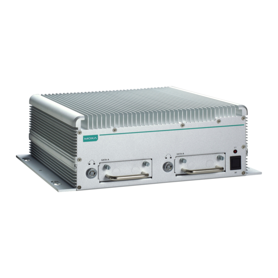
Page 10: Appearance
V2616A Hardware Manual Hardware Introduction Appearance Front View Rear View... -
Page 11: Dimensions
V2616A Hardware Manual Hardware Introduction Dimensions LED Indicators LED Name LED Color LED Function Power Green Power is on and functioning normally Power is off, or has failed Storage Yellow CFast card/HDD/SSD is transmitting data. CFast card/HDD/SSD is not transmitting data. LAN (1, 2) Green 100 Mbps Ethernet mode... -
Page 12: Real Time Clock
V2616A Hardware Manual Hardware Introduction Real Time Clock The embedded computer’s real-time clock is powered by a lithium battery. We strongly recommend that you NOT replace the lithium battery on your own. If the battery needs to be changed, contact the Moxa RMA service team. -
Page 13: Hardware Connection Description
Hardware Connection Description In this chapter, we show how to connect the embedded computers to the network and to a variety of common devices. The following topics are covered in this chapter: Installing the V2616A Wiring Requirements Connecting the Power ... -
Page 14: Installing The V2616A
V2616A Hardware Manual Hardware Connection Description Installing the V2616A Wall or Cabinet Mounting The V2616A comes with two wall-mounting brackets. Use two screws per side to attach the V2616A to a wall or cabinet. Wiring Requirements This section describes how to connect peripheral devices to the embedded computer. You should read and follow these common safety precautions before proceeding with the installation of any electronic device: •... -
Page 15: Connecting The Power
V2616A Hardware Manual Hardware Connection Description Connecting the Power Connect the 24 to 110 VDC power line with M12 connector to the V2616A computer. If the power is supplied properly, the Ready LED will glow a solid green after a 25 to 30 second delay. Grounding the Unit SG: The Shielded Ground (sometimes called Protected Ground) contact is the central pin of the power input connector. -
Page 16: Installing A Cfast Card
V2616A Hardware Manual Hardware Connection Description DB9 Male Port RS-232/422/485 Pinouts RS-232 RS-422 RS-485-4W RS-485-2W TxDA(-) TxDA(-) – TxDB(+) TxDB(+) – RxDB(+) RxDB(+) DataB(+) RxDA(-) RxDA(-) DataA(-) – – – – – – – – – NOTE This is the pin assignment for the computer-side connectors on the V2616A shell. If you are wiring peripheral-side connectors for a serial cable, you will need to mirror the pin assignment. -
Page 17: Connecting An Audio Input
V2616A Hardware Manual Hardware Connection Description Connecting an Audio Input The V2616A comes with an M12 X-coded audio input/output connector, allowing users to connect a speaker or an earphone. Audio Line-in, right Line in plug-in detected Line-in, left Line-out, left Line out, plug-in detected Line-out, right NOTE... -
Page 18: Connecting To A Vga Monitor
V2616A Hardware Manual Hardware Connection Description Connecting to a VGA Monitor The V2616A comes with a D-Sub 15-pin female connector on the front panel to connect a VGA monitor. To ensure that the monitor image remains clear, be sure to tighten the monitor cable after connecting it to the V2616A. -
Page 19: Connecting To Usb Ports
V2616A Hardware Manual Hardware Connection Description Connecting to the USB Ports On its rear panel the V2616A has an X-coded M12 USB 2.0 port, as well as 2 type A USB 2.0 ports. The hosts can be used for an external flash disk or hard drive for storing large amounts of data. You can also use these USB hosts to connect to a keyboard or a mouse. -
Page 20: Making A Storage Drive Hot-Swappable
V2616A Hardware Manual Hardware Connection Description 3. Fasten the two screws on each side of the hard disk (total of four). 4. Install the storage kit into the V2616A computer. Fasten four screws on the kit, and connect the cable the power onto the V2616A’s main board. - Page 21 V2616A Hardware Manual Hardware Connection Description 3. Pull out the faceplate by unscrewing the thumbscrews in the upper corners, and then remove the plate. Fasten the storage drive to the faceplate flange as shown below, using the two flathead screws that were shipped with your V2616A.
-
Page 22: Upgrading The Memory Module
V2616A Hardware Manual Hardware Connection Description Upgrading the Memory Module V2616A embedded computers come with two 200-pin, DDR3-1600 SODIMM memory slots that can provide up to 16 GB of memory. One 4 GB memory module is installed at the factory. To upgrade a memory module, follow these instructions: 1. -
Page 23: Installing The Mini Pcie Module
V2616A Hardware Manual Hardware Connection Description Installing the Mini PCIe Module The V2616A computer comes with a mini PCIe socket, allowing users to install a mini PCIe module like those used for cellular communications. Follow these steps to installation a module. 1. - Page 24 V2616A Hardware Manual Hardware Connection Description 4. Connect the cellular antenna cable to the module. 5. Pass the connector of the antenna cable through the antenna hole on the rear panel of the computer. You may use either the W1 or W2 hole. Pass the locking washer over the outer end of the connector first, and then fasten the nut to lock the connector against the face of the computer.
-
Page 25: Bios Setup
BIOS Setup This chapter describes the BIOS settings of the V2616A computer. The BIOS is a set of input/output control routines for peripherals. The BIOS is used to initialize basic peripherals and helps boot the operating system before the operating system is loaded. The BIOS setup allows the user to modify the system configurations of these basic input/output peripherals. -
Page 26: Entering The Bios Setup
V2616A Hardware Manual BIOS Setup Entering the BIOS Setup To enter the BIOS setup utility, press the F2 key while the system is booting up. The main BIOS Setup screen will appear. Four options will be available. Continue: Continue to boot up Boot Manager: Select the device for booting up Boot From File: Select the UEFI boot up file SCU: Enter the BIOS configuration step. -
Page 27: Main Information
V2616A Hardware Manual BIOS Setup Main Information The main page indicates the system information, such as model name, BIOS version, and CPU type. Users may view the basic system hardware information in the page. Note: the information for Processor Type will vary depending on the different models that you purchase. Advanced Settings The “Advanced Features”... -
Page 28: Boot Configuration
V2616A Hardware Manual BIOS Setup Boot Configuration This item allows users to configure the default value of Numlock. Option: On (default), Off. HDC Configuration The host drive controller may be configured for IDE or AHCI mode (default). When the AHCI mode is selected, the following screen will appear. -
Page 29: Video Configuration
V2616A Hardware Manual BIOS Setup Serial ATA Port 0 to 4 This setting allows the user to display information about the installed drives. AHCI SALP Note that AHCI SALP will only appear when AHCI mode is selected. This item allows you to enable aggressive link power management (SALP) in AHCI. - Page 30 V2616A Hardware Manual BIOS Setup Internal Graphics Device This option allows you to enable/disable the internal graphics device. IGD—DVMT Pre-Allocated This item allows you to configure pre-allocated memory capacity for the IGD. Pre-allocated graphics memory is invisible to the operating system. Options: 64 MB (default), 32 MB, 96 MB, 128 MB, 256 MB, 512 MB DVMT is a BIOS solution where “the optimum amount of memory is dynamically allocated and de-allocated as needed for balanced graphics and system performance, through Intel®...
-
Page 31: Chipset Configuration
V2616A Hardware Manual BIOS Setup Chipset Configuration This item allows you to configure the chipset settings. Power ON after Power Fail This item allows you to enable the computer form automatically powering up after a system crash. Options: ON (default) Power Button This item allows you to enable/disable the power button. -
Page 32: Pci Express Configuration
V2616A Hardware Manual BIOS Setup DO-1 Level This item allows you set the DO-1 as high or low status. Options: High (default), Low. PCI Express Configuration PCIe Speed This item allows you to configure the speed of the mini PCIe interface. Option: Auto (default), Gen1, Gen2 Hardware Monitor This item allows you to view stats like CPU and system temperature, voltage levels. -
Page 33: Smart Recovery Info
V2616A Hardware Manual BIOS Setup Smart Recovery Info This items allows you to view the Smart Recovery information. Load Smart Recovery Default This item allows you to load Smart Recovery default value. Refer to the Smart Recovery Website: http://www.moxa.com/product/Smart-Recovery.htm Options: Yes (default), No Security Settings This section allows users to configure security settings with a supervisor password. -
Page 34: Set Supervisor Password
V2616A Hardware Manual BIOS Setup Set Supervisor Password This item allows you set the supervisor password. Select and then enter the password, and then confirm the password again. To delete the password, enter Set Supervisor Password and then enter the old password; then, leave the new password fields blank, and press enter. -
Page 35: Wake On Lan
V2616A Hardware Manual BIOS Setup Options: Disabled (default); By Every Day (user specifies a regular daily time when the computer will power up); By Day of Month (user specified a regular day each month when the computer will power up) Wake on LAN This feature is used to wake on the system by a LAN device from a remote host. -
Page 36: Boot Settings
V2616A Hardware Manual BIOS Setup Boot Settings The section allows users to configure boot settings. Boot Type This item allows you to enable/disable quick boot function. Options: Dual Boot Type (default), Legacy Boot Type, UEFI Boot Type. PXE Boot to LAN This item allows you to enable/disable PXE boot to LAN function. -
Page 37: Efi Device First
V2616A Hardware Manual BIOS Setup EFI Device First This item allows you to determine EFI device first or legacy device first. If enabled, EFI device will be the first; if disabled, legacy device will be the first. Options: Disabled (default), Enabled Boot Delay Time This item allows you to configure the delay time value for users to input hot key during POST time. -
Page 38: Exit Settings
V2616A Hardware Manual BIOS Setup Exit Settings The section allows users to exit the BIOS environment. Exit Saving Changes This item allows you to exit the BIOS environment and save the values you have just configured. Options: Yes (default), No Save Change Without Exit This item allows you to save changes without exiting the BIOS environment. -
Page 39: Save Custom Defaults
V2616A Hardware Manual BIOS Setup Save Custom Defaults This item allows you to save the current BIOS values as a “custom default” that may be reverted to at any time by the “load custom defaults” selection just above. Options: Yes (default), No Discard Changes This item allows you to discard all settings you have just configured. - Page 40 V2616A Hardware Manual BIOS Setup Step 2: Prepare the Upgrade File You must use the BIOS upgrade installation file to upgrade the BIOS. Contact Moxa’s technical department for assistance. 1. Get the BIOS upgrade installation file. The file name should have following format: V2616AxxSx.exe (xx refers to version numbers).
- Page 41 V2616A Hardware Manual BIOS Setup 6. When the upgrade is finished, the computer will automatically reboot. You may check the BIOS version in Main page of the BIOS Setup ATTENTION Do NOT switch off the power supply during the BIOS upgrade, since doing so may cause the system to crash. 4-17...
-
Page 42: Regulatory Approval Statement
Regulatory Approval Statement This device complies with part 15 of the FCC Rules. Operation is subject to the following two conditions: (1) This device may not cause harmful interference, and (2) this device must accept any interference received, including interference that may cause undesired operation.
Need help?
Do you have a question about the V2616A Series and is the answer not in the manual?
Questions and answers