
Related Manuals for Moxa Technologies V2403C Series


Summary of Contents for Moxa Technologies V2403C Series
- Page 1 V2403C Series Hardware User Manual Version 1.0, January 2022 www.moxa.com/products © 2022 Moxa Inc. All rights reserved.
- Page 2 V2403C Series Hardware User Manual The software described in this manual is furnished under a license agreement and may be used only in accordance with the terms of that agreement. Copyright Notice © 2022 Moxa Inc. All rights reserved. Trademarks The MOXA logo is a registered trademark of Moxa Inc.
-
Page 3: Table Of Contents
Table of Contents Introduction ............................5 Overview .............................. 5 Package Checklist ..........................5 Product Features ........................... 5 Hardware Specifications ......................... 5 Hardware Block Diagram ........................6 Hardware Introduction ......................... 7 Appearance ............................7 Dimensions ............................8 LED Indicators ............................8 Real-time Clock ............................. - Page 4 mPCIE#2 Power ........................... 50 Boot Settings ............................51 Boot Type ............................ 51 Network Stack ..........................51 PXE Boot capability ........................51 USB Boot ............................ 52 Timeout ............................52 EFI ............................. 52 Enabling AMT ............................52 Exit Settings ............................55 Exit Saving Changes ........................56 Save Change Without Exit ......................
-
Page 5: Introduction
This chapter gives a general overview of the V2403C computer’s hardware features and specifications. Overview The V2403C Series embedded computers are based on an Intel® 7th Gen processor and feature 4 RS- 232/422/485 serial ports, 4 Ethernet ports, and 4 USB 3.0 hosts. In addition, the computers provide 1 DisplayPort output and 1 HDMI display with 4k resolution support. -
Page 6: Hardware Block Diagram
Hardware Block Diagram V2403C Series Hardware User Manual... -
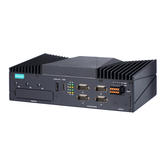
Page 7: Hardware Introduction
APIs and device drivers. Appearance Front View V2403C Series Hardware User Manual... -
Page 8: Dimensions
Tx: Data transmission is in progress Serial Yellow Rx: Receiving Data No operation Yellow Data is being accessed from either the mSATA or the SATA drive Storage Data is not being accessed from the storage drives V2403C Series Hardware User Manual... -
Page 9: Real-Time Clock
Contact the Moxa RMA service team if you need to replace your battery. Caution Dispose of used batteries in a suitable manner. Consult the battery manufacturer for details on disposing batteries. V2403C Series Hardware User Manual... -
Page 10: Hardware Connection Description
Ensure that the mounting brackets are attached to the V2403C computer in the direction shown in the following figure. The eight screws are included in the package. They are standard IMS_M3x5L screws and require a torque of 4.5 kgf-cm. Refer to the following illustration for details. V2403C Series Hardware User Manual... -
Page 11: Wiring Requirements
If the current goes above the maximum ratings, the wiring could overheat, causing serious damage to your equipment. Temperature Caution! Be careful when handling the unit. When the unit is plugged in, the internal components generate heat, and consequently the outer casing may feel hot to the touch. V2403C Series Hardware User Manual... -
Page 12: Connecting The Power
For surge protection, connect the grounding connector located below the power connector with the earth (ground) or a metal surface. Grounding the Unit In addition, a grounding connector is also provided below the power input connector. Connect the wire to an appropriately grounded metal surface. V2403C Series Hardware User Manual... -
Page 13: Configuring The Ignition Control Switch
Refer to the following table for the detailed switch number and the corresponding power on time and power off time. IGT Function Switch Number PWR on Time (sec) PWR off Time (sec) Not available Not available V2403C Series Hardware User Manual... -
Page 14: Connecting Data Transmission Cables
– TRD(2)- ERx- TRD(1)- – TRD(3)+ – TRD(3)- Connecting to a Serial Device The V2403C comes with four serial ports, which can be configure for RS-232/422/485 interfaces. These ports are located on the rear panel. V2403C Series Hardware User Manual... -
Page 15: Connecting An Audio Input And Output
The V2403C comes with a Line-in and a Line-out with 35 mm jack plug connectors, allowing users to connect a speaker or an earphone. Digital Input/Output The V2403C comes with a 4-channel digital input and a 4-channel digital output through a terminal block connector. V2403C Series Hardware User Manual... -
Page 16: Connecting To Display Monitors
V2403C. In addition, an HDMI connector is also provided on the rear panel, allowing users to connect another display with an HDMI interface. V2403C Series Hardware User Manual... -
Page 17: Connecting To The Usb Ports
The V2403C comes with two storage sockets for installing 2.5-inch storage disks. Follow these steps to install a hard disk drive. Unpack the storage disk tray from the product Place the disk drive on the tray. package. V2403C Series Hardware User Manual... - Page 18 Remove all screws on the rear panel of the V2403C computer. Take out the rear cover of the computer and find the location of the storage sockets. There are two sockets A and B and either can be used. V2403C Series Hardware User Manual...
- Page 19 Push the tray upwards (towards the groove) in the socket so that the connectors on the storage disk tray and the socket can be connected. Fasten the two screws on the bottom of the tray to secure it in place. V2403C Series Hardware User Manual...
-
Page 20: Installing The Sim Cards
Find the SIM card holder cover on the front panel. Unfasten the two screws on the cover and remove the cover. Each cellular module supports dual SIM cards; the location of the SIM card slots is indicated in the following diagram: V2403C Series Hardware User Manual... -
Page 21: Installing The Wi-Fi Module
To remove the SIM card, simply push in the SIM card to release it and pull out the SIM card. Put back the cover on the SIM card slot. Installing the Wi-Fi Module Follow these steps to install the Wi-Fi Module. Remove the wall-mounting kit brackets. V2403C Series Hardware User Manual... - Page 22 There are two sockets; you can install your Wi-Fi module on either one. However, we strongly suggest you install the Wi-Fi module on Socket 2, as it is closer to the antenna connectors located on the front panel. Check the Wi-Fi module package contents. V2403C Series Hardware User Manual...
- Page 23 Place the Wi-Fi module in the socket and connect the antenna cables to the connectors. There are three cables, you may use any two to connect onto the Wi-Fi module. Place the protection cover on the antenna cable connectors and secure the cover with the two screws in the package. V2403C Series Hardware User Manual...
-
Page 24: Installing The Cellular Module
Insert the module in the socket and secure it with the two screws in the package. We strongly suggest you install the cellular module on the Socket 1, as it is closer to the antenna holes on the rear panel. Connect the three antenna cables on the connectors. V2403C Series Hardware User Manual... -
Page 25: Installing The Wireless Cables And Antennas
The Wi-Fi antenna connectors are of the SMA type and are located on the front panel. Connect the antenna on to the connector and tightened it to ensure that it is secure. V2403C Series Hardware User Manual... -
Page 26: Installing The Cellular Module Antennas
On the other end of the connector, pass the antenna mount’s threaded connection ring through the mounting hole, hold the locking washer against the rear panel and secure the antenna connector by tightening the nut onto the threaded protection ring. Use the same method to install another two antenna connectors. V2403C Series Hardware User Manual... -
Page 27: Switching The Wireless Module Socket
Status Socket 1 Socket 2 ON (default) Wi-Fi Wi-Fi Cellular Cellular For example, if you install a cellular module in the first socket, you need to turn the DIP switch 1 to OFF. V2403C Series Hardware User Manual... -
Page 28: Installing The Msata Drive
Remove the rear cover of the computer, the mSATA socket is located in the central part of the computer as indicated in the following diagram. Insert the mSATA module into the socket and fasten two screws to secure the module. V2403C Series Hardware User Manual... -
Page 29: Upgrading The Memory
There two memory slots located inside the computer. Insert the new memory card into the first slot, pull in the clutches, and push down the memory card. Ensure that the memory card in securely inserted. V2403C Series Hardware User Manual... -
Page 30: Replacing The Battery
The V2403C comes with one battery slot containing a lithium battery with the specifications 3V/195 mAh. To replace the battery, do the following: The battery cover is located on the rear panel of the computer. Unfasten the two screws on the battery cover. V2403C Series Hardware User Manual... - Page 31 Replace the battery, place the metal plate on the battery, and fasten the screws to secure the batteries. Reconnector the connectors, place the battery into the slot, and put back the cover. Secure the cover with the two screws. V2403C Series Hardware User Manual...
- Page 32 This computer is designed to be supplied by listed equipment and rated 12 to 48 VDC, minimum 5.83 to 1.46 A, minimal Tma=70°C. If you need assistance with purchasing a power adapter, contact Moxa technical support team. V2403C Series Hardware User Manual...
-
Page 33: Bios Setup
Setup Utility: Enter the BIOS configuration menu • Intel® Management Engine BIOS Extension: Enter the AMT configuration menu • NOTE The Intel® AMT function is supported only in the models with i5, i7 processors. Select F2 to enter the BIOS configuration. V2403C Series Hardware User Manual... - Page 34 The BIOS configuration screen will be shown when you enter the Setup Utility option, as shown in the following figure: NOTE The Processor Type information will vary depending on the model that you have purchased. V2403C Series Hardware User Manual...
-
Page 35: Main Page
Main Page The Main page displays basic system hardware information, such as model name, BIOS version, and CPU type. V2403C Series Hardware User Manual... -
Page 36: Advanced Settings
Advanced Settings Select the Advanced tab in the main menu to open the advanced features screen. NOTE The Active Management Technology is not supported in the KL1 and KL3 models. V2403C Series Hardware User Manual... -
Page 37: Boot Configuration
Boot Configuration This item allows users to configure the default value of Numlock. Options: On (default), Off. V2403C Series Hardware User Manual... -
Page 38: Sata Configuration
This setting allows you to enable/disable hot-plug capability (the ability to remove the drive while the computer is running) for installed storage drives. Options: Enabled (default for Port 0/1), Disabled (default for Port 2 (mSATA)) V2403C Series Hardware User Manual... - Page 39 Source: http://en.wikipedia.org/wiki/Standard_RAID_levels for details. When setting the Intel RST Premium mode, or saving changes and reboot, you can select Device Management to configure the following Intel Rapid Storage Technology. V2403C Series Hardware User Manual...
-
Page 40: Intel Rapid Storage Technology
Intel Rapid Storage Technology This section allows users to configure Intel® Rapid Storage Technology. V2403C Series Hardware User Manual... -
Page 41: Cpu Configuration
This item indicates the number of cores to enable in each processor package. Hyper-Threading This feature makes the processor resources work more efficiently, enabling multiple threads to run on each core. It also increases processor throughput, improving overall performance on threaded software. Options: Disabled, Enabled (default) V2403C Series Hardware User Manual... -
Page 42: Active Management Technology Support
Unconfigure ME on RTC Clear State Disabling this option will cause ME not to unconfigure on RTC clear. Options: Disabled, Enabled (default) Unconfigure ME Unconfigure ME by resetting the MEBx password to the default password. V2403C Series Hardware User Manual... -
Page 43: Video Configuration
2D/3D graphics performance. DVMT Total Gfx Mem. This item allows you to configure the maximum amount of memory DVMT will use when allocating additional memory for the internal graphics device. Options: 256 MB (default), 128 MB, Max. V2403C Series Hardware User Manual... -
Page 44: Chipset Configuration
This item allows users to set the DO 2 to high or low. Options: High (default), Low DO-3 Level This item allows users to set the DO 3 to high or low. Options: High (default), Low V2403C Series Hardware User Manual... -
Page 45: Sio Ite8786E
Auto (default): EFI/OS chooses the resources Serial Port C This function allows users to configure the resources for the serial port A. Disable: No resources Enable: User configures the resources Auto (default): EFI/OS chooses the resources V2403C Series Hardware User Manual... -
Page 46: Console Redirection
This item allows you to view stats such as CPU and system temperature, voltage levels, and other chipset information. Console Redirection When the Console Redirection Function is enabled, the console information will be output to both the HDMI monitor and through the serial port. Options: Disabled (default), Enabled V2403C Series Hardware User Manual... -
Page 47: Security Settings
The TPM module is an optional module that needs to be purchased seperately. Contact a Moxa representative for details. TPM State This item allows you view the status of current TPM settings. Clear TPM This item allows users to remove all TPM context associated with a specific owner. V2403C Series Hardware User Manual... -
Page 48: Set Supervisor Password
This item allows you to set the supervisor password. Select the Set Supervisor Password option and enter the password and confirm the password again. To delete the password, select the Set Supervisor Password option and enter the old password; leave the new password fields blank, and then press enter. V2403C Series Hardware User Manual... - Page 49 Enable: System will ask input password on post time. Disable: System will ask for the password to go to the setup utility. Config-Only: System will only ask for the password when you select the config (F2) option V2403C Series Hardware User Manual...
-
Page 50: Power Settings
This item allows you to control the power in the 1st mPCIe connector. Options: Off (default), on mPCIE#2 Power This item allows you to control the power in the 2nd mPCIe connector. Options: Off (default), on V2403C Series Hardware User Manual... -
Page 51: Boot Settings
Options: Disabled (default), Enabled PXE Boot capability PXE Booting is booting a system over a network. This item allows users to start PXE over IPv4 or IPv6 Options: Disabled (default), UEFI: IPv4, UEFI: IPv6, UEFI: IPv4/IPv6 V2403C Series Hardware User Manual... -
Page 52: Usb Boot
To enter the BIOS setup utility, press the “F2” key while the system is booting up. The main BIOS Setup screen will appear. Five options will be available: Select Intel® Management Engine BIOS Extension to enter the AMT configuration. V2403C Series Hardware User Manual... - Page 53 Press <Enter> to start the login procedure. Type the default password admin. V2403C Series Hardware User Manual...
- Page 54 Select Intel® AMT Configuration to enable remote access without a local user present for consent, select User Consent, and then select User Opt-in and change the value to None. Set static IP or DHCP by request. V2403C Series Hardware User Manual...
-
Page 55: Exit Settings
Set Activate Network Access to enable remote access capability. Exit Settings The section allows users to exit the BIOS environment. V2403C Series Hardware User Manual... -
Page 56: Exit Saving Changes
This item allows you to save the current BIOS values as a “custom default” that may be reverted to at any time by the “load custom defaults” selection just above. Options: Yes (default), No Discard Changes This item allows you to discard all settings you have just configured. Options: Yes (default), No V2403C Series Hardware User Manual... -
Page 57: Remote Management Using Amt
Click on “Log On” and type the username (admin) and password to log in and control the V2403C remotely. NOTE The V2403C’s AMT port is LAN1. NOTE Refer to the Intel AMT Implementation and Reference Guide for details: https://software.intel.com/sites/manageability/AMT_Implementation_and_Reference_Guide/ default.htm?turl=WordDocuments%2Faccessingintelamtviathewebuiinterface.htm V2403C Series Hardware User Manual... -
Page 58: Upgrading The Bios
Step 1: Create a Bootable USB Disk Before upgrading the BIOS, every user should first create a bootable USB drive as a system boot device. Search “format”, then select Create and format hard disk partitions. V2403C Series Hardware User Manual... - Page 59 You must use the BIOS upgrade installation file to upgrade the BIOS. Contact Moxa’s technical department for assistance. Get the BIOS upgrade file; it includes an efi folder and a file xxxx.efi. Copy efi folder and xxxx.efi file to the Bootable USB Disk. V2403C Series Hardware User Manual...
- Page 60 Screen will switch to the SHELL environment, type fs0: then, go to the directory where the upgrade file is located, and type xxxxxx.efi (the name is based on the upgrade file you get from Moxa). The upgrade program will run automatically. Wait patiently until the procedure is finished. V2403C Series Hardware User Manual...
- Page 61 Go each fsx (x means number), then type ls to view the content of the boot device. If find the upgrade file, execute it. ATTENTION Do NOT switch off the power supply during the BIOS upgrade, since doing so may cause the system to crash. V2403C Series Hardware User Manual...
-
Page 62: Regulatory Approval Statement
European Community WARNING This is a class A product. In a domestic environment this product may cause radio interference in which case the user may be required to take adequate measures. V2403C Series Hardware User Manual...
Need help?
Do you have a question about the V2403C Series and is the answer not in the manual?
Questions and answers