
Related Manuals for Moxa Technologies V2101 Series


Summary of Contents for Moxa Technologies V2101 Series
- Page 1 V2101 Hardware User’s Manual www.moxa.com/product Second Edition, January 2010 © 2010 Moxa Inc. All rights reserved. Reproduction without permission is prohibited.
-
Page 2: Copyright Notice
Information in this document is subject to change without notice and does not represent a commitment on the part of Moxa. Moxa provides this document “as is,” without warranty of any kind, either expressed or implied, including, but not limited to, its particular purpose. Moxa reserves the right to make improvements and/or changes to this manual, or to the products and/or the programs described in this manual, at any time. -
Page 3: Table Of Contents
LED Indicators ......................2-3 Reset Button ....................... 2-4 Real Time Clock......................2-4 Chapter 3 Hardware Connection Description .............3-1 Installing the V2101 ....................3-2 Wiring Requirements ....................3-4 Connecting the Power ..................3-4 Grounding the Unit ................... 3-4 Connecting Data Transmission Cables............... 3-5 Connecting to the Network ................ - Page 4 Appendix A Regulatory Approval Statement ..............A-1...
-
Page 5: Chapter 1 Introduction
The V2101 embedded computers are based on the Intel Atom Z510PT x86 processor, and feature 2 serial ports, dual Gigabit LAN ports, 4 USB 2.0 hosts, and an SD socket. The V2101 Series offers both VGA and LVDS outputs, making it particularly well-suited for industrial applications, such as SCADA and factory automation. -
Page 6: Overview
The V2101 embedded computers are based on the Intel Atom Z510PT x86 processor, and feature 2 serial ports, dual Gigabit LAN ports, 4 USB 2.0 hosts, and an SD socket. The V2101 Series offers both VGA and LVDS outputs, making it particularly well-suited for industrial applications, such as SCADA and factory automation. -
Page 7: Product Features
V2101 HW User’s Manual Introduction Product Features V2101 series embedded computers have the following features: Intel Atom Z510PT 1.1 GHz processor, 400 MHz FSB DDR2 SODIMM socket, supporting DDR2 400 up to 2 GB Dual independent displays (VGA + LVDS) 2 Gigabit Ethernet ports 4 USB 2.0 ports for high speed peripherals... - Page 8 V2101 HW User’s Manual Introduction Protection Serial Interface Serial Standards 2 RS-232/422/485 ports, software selectable (DB9 male) Serial Communication Parameters Data Bits 5, 6, 7, 8 Stop Bits 1, 1.5, 2 Parity Non, Even, Odd, Space, Mark Serial Signals RS-232...
-
Page 9: Hardware Block Diagram
V2101 HW User’s Manual Introduction Power Requirements Input Voltage 9-36 VDC (3-pin terminal block for V+, V-, SG) Power Consumption With no load on 4 USB ports: (without connecting the 1.88 A @ 9 VDC, 17 W LVDS panel) 583 mA @ 24 VDC 14 W... -
Page 10: Chapter 2 Hardware Introduction
Hardware Introduction Chapter 2 The V2101 series embedded computers are compact, well-designed, and built rugged enough for industrial applications. LED indicators help you monitor performance and identify trouble spots, multiple serial ports allow you to connect different devices for wireless operation, and the reliable and stable hardware platform lets you devote your attention to developing your applications. -
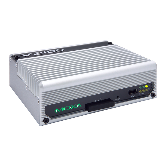
Page 11: Appearance
V2101 HW User’s Manual Hardware Introduction Appearance V2101 Front View Side View LED Indicators (Tx, Rx) Reset Button LVDS Output SD Socket USB 2.0 Host x 1 LED Indicators (Power/Storage) Rear View Power Input DI x 3/DO x 3 10/100/1000 Mbps USB 2.0 Host x 3... -
Page 12: Dimensions
V2101 HW User’s Manual Hardware Introduction Dimensions V2101 LED Indicators LED Name LED Color LED Function Power is on and functioning normally Green Power Power is off or a power error exists SD card is detected Yellow Storage SD card is not detected... -
Page 13: Reset Button
Hardware Introduction Reset Button Press the Reset Button on the front panel of the V2101 to reboot the system automatically. The Ready LED will blink on and off for the first 5 seconds, and then maintain a steady glow once the system has rebooted. -
Page 14: Hardware Connection Description
Hardware Connection Description Chapter 3 The V2101 series embedded computers support multiple connection types, including serial port communication, USB ports for storage expansion, and DI/DO channels. In addition, the computers provide either a VGA or LVDS output for field site monitoring. In this chapter, we show how to connect the embedded computers to the network and to various devices. -
Page 15: Installing The V2101
Installing the V2101 DIN-Rail Mounting Step 1: Use two screws to attach the DIN-rail attachment plate to the bottom of the V2101. When attaching the plate to the V2101, make sure that the stiff metal spring is at the top. - Page 16 VESA Mounting (not included in the Package) The V2101 has four screw holes on the bottom panel for attaching the computer to a 75 x 75 mm VESA mounting kit. Use four screws to attach the computer to the VESA mounting kit.
-
Page 17: Wiring Requirements
It is advisable to label the wiring to all devices in the system. ATTENTION Safety First! Be sure to disconnect the power cord before installing and/or wiring your V2101. Wiring Caution! Calculate the maximum possible current in each power wire and common wire. Observe all electrical codes dictating the maximum current allowable for each wire size. -
Page 18: Connecting Data Transmission Cables
Connect the SG wire to an appropriate grounded metal surface. Connecting Data Transmission Cables This section describes how to connect the V2101 embedded computers to the network and serial devices. Connecting to the Network Plug your network cable into the embedded computer’s Ethernet port. The other end of the cable should be plugged into your Ethernet network. -
Page 19: Connecting To A Serial Device
16 GB of additional memory. The following steps show how to install the SD card. The SD slot is located in the middle of the V2101’s front panel. To install an SD card, make sure the embedded computer is powered off, remove the protective cover from the left to access the slot, and then plug the SD card directly into the slot. -
Page 20: Connecting To The Usb Device
USB Device The V2101 comes with 4 USB 2.0 hosts. One is located on the front panel and the other three are on the rear panel. The hosts can be used for an external flash disk or hard drive for storing large amounts of data. -
Page 21: Di/Do
DO 0 DI 0 DI 2 Connec ting to a VGA Monitor The V2101 comes with a D-Sub 15-pin female connector on the rear panel to connect a VG A CRT nitor. To ensure that the mon itor image re... -
Page 22: Connecting To An Lvds Monitor
V2101 HW User’s Manual Hardware Connection Description Connec ting to an LVDS Monitor The V2101 also comes with a 26-pin LV DS connector on the side panel t onnect a panel with LVDS cable. The pin assi ments of the LVDS connector ar e sho wn below. -
Page 23: Connecting To A Speaker Or A Headphone
V2101 HW User’s Manual Hardware Connection Description Connec ting to a Speaker or a Headphone The V2101 comes with audio input and output interfaces for connecting a microphone and speaker or headphones. See the following figure for details. Audio Input Audio Output... -
Page 24: Chapter 4 Bios Setup
BIOS Setup Chapter 4 This chapter describes the BIOS settings of the V2101 embedded computers. The BIOS is a set of input/output control routines for peripherals. The BIOS is used to initialize basic peripherals and helps boot the operating system before the operating system is loaded. The BIOS setup allows the user to modify the system configurations of these basic input/output peripherals. -
Page 25: Entering The Bios Setup Utility
V2101 HW User’s Manual BIOS Setup Entering the BIOS Setup Utility To enter the BIOS setup utility, press the “Del” key while the system is booting up. The main BIOS Setup screen will appear. A basic description of each function key is listed at the bottom of the screen. Refer to these descriptions to learn how to scroll about the screen, how to select by pressing “Enter,”... -
Page 26: Modifying The Bios Main Settings
V2101 HW User’s Manual BIOS Setup Modifying the BIOS Main Settings Basic Configuration After entering the BIOS Setup, or choosing the “Main” option, the BIOS main menu will be displayed. Use this menu to check the basic system information such as memory and IDE hard drive. -
Page 27: Advanced Settings
V2101 HW User’s Manual BIOS Setup Advanced Settings The “Advanced Features” screen will appear when choosing the “Advanced” item from the main menu. Hard Disk Boot Priority First/Second/Third Boot Device This option allows users to select or change the device boot priority. You may set 3 levels of priority to determine the boot up sequence for different bootable devices, such as a hard drive, CD-ROM, and removable devices. -
Page 28: Advanced Bios Features
V2101 HW User’s Manual BIOS Setup Advanced BIOS Features When you select the “Advanced BIOS Features” option under the “Advanced” menu, the following configuration menu will appear. CPU Features C1E Function This item allows you to configure the power-saving mode when the CPU is in C1 status. -
Page 29: Advanced Chipset Settings
V2101 HW User’s Manual BIOS Setup Advanced Chipset Settings On-chip Frame Buffer Size This item determines the frame buffer size for the VGA function, and will share the system memory. Options: 1 MB, 4 MB, 8 MB (default), Boot Type This item determines the boot type of the display. -
Page 30: Peripherals
V2101 HW User’s Manual BIOS Setup ATTENTION Note that you must select the correct resolution for your LVDS display based on your LVDS specifications, or it will not be properly shown on your panel. When you encounter this problem, take the following steps: 1. -
Page 31: Onchip Ide Device
V2101 HW User’s Manual BIOS Setup OnChip IDE Device IDE HDD Block Mode Block mode is otherwise known as block transfer, multiple commands, or multiple sector read/write. Select the “Enabled” option if your IDE hard drive supports block mode (most new drives do). -
Page 32: Onboard Device
V2101 HW User’s Manual BIOS Setup Onboard Device Intel HD Audio Controller This feature allows you to enable/disable the HD audio controller. Options: Auto (default), Disabled SDIO/MMC Controller This feature allows you to enable/disable the SD controller. Options: Enabled (default), Disabled Onboard LAN Boot ROM Decide whether to invoke the boot ROM of the onboard LAN chip. -
Page 33: Onboard I/O Chip Setup
Onboard I/O Chip Setup Onboard Serial Port 1 This function allows you to enable/disable serial port 1 communication. The V2101 computer will automatically distribute the IRQ value for serial port 1 as the default value. If you wish to disable, select Disabled. -
Page 34: Power
BIOS Setup Debug Port This function allows you to enable/disable the debug port communication. The V2101 computer will automatically distribute the IRQ value for the debug port as the default value. If you wish to disable, select Disabled. This port is only for engineers who are debugging programs. -
Page 35: Hardware Monitor
V2101 HW User’s Manual BIOS Setup Hardware Monitor This item helps monitor the status of the system, including CPU temperature and the voltage of the CPU, SDRAM and battery. Load Defaults 4-12... -
Page 36: Exiting The Bios Setup
V2101 HW User’s Manual BIOS Setup Load System Default Settings Use this option to load system factory default settings instead of the current BIOS settings. This option is useful for when the system is unstable. Users do not need to remember what settings were active before the system fails. -
Page 37: Upgrading The Bios
This section describes how to upgrade the BIOS. However, please note that upgrading the BIOS involves high risk of damage to your computer. We strongly recommend that you contact Moxa’s TS staff for assistance and obtain all necessary tools and files before attempting to upgrade. - Page 38 V2101 HW User’s Manual BIOS Setup ATTENTION We suggest you use a USB drive with under 2 GB in disk space, as larger USB drives may not support FAT file format and consequently fail to boot. Step 2: Prepare the Upgrade Tool and BIOS Binary File.
- Page 39 V2101 HW User’s Manual BIOS Setup 5. Press “+” to move it up to the first priority, and press “Esc” to exit the setup menu. 6. Make sure the first boot device is Hard Disk. If it isn’t, press Enter to change it.
- Page 40 V2101 HW User’s Manual BIOS Setup Step 4: Run awdflash.exe to upgrade the BIOS. 1. While in the BIOS Setup menu and before upgrading the BIOS, you may choose to save the old BIOS files to a specific location. Type Y to do so, or N to begin the upgrade.
- Page 41 Chapter A Regulatory Approval Statement Appendix A This device complies with part 15 of the FCC Rules. Operation is subject to the following two conditions: (1) This device may not cause harmful interference, and (2) this device must accept any interference received, including interference that may cause undesired operation.
Need help?
Do you have a question about the V2101 Series and is the answer not in the manual?
Questions and answers