
Related Manuals for Moxa Technologies V2406C


Summary of Contents for Moxa Technologies V2406C
- Page 1 V2406C Hardware User’s Manual Version 1.1, July 2020 www.moxa.com/product © 2020 Moxa Inc. All rights reserved.
- Page 2 V2406C Hardware User’s Manual The software described in this manual is furnished under a license agreement and may be used only in accordance with the terms of that agreement. Copyright Notice © 2020 Moxa Inc. All rights reserved. Trademarks The MOXA logo is a registered trademark of Moxa Inc.
-
Page 3: Table Of Contents
Dimensions ............................2-3 LED Indicators ............................ 2-3 Real-time Clock ..........................2-4 Hardware Connection Description ..................... 3-1 Installing the V2406C .......................... 3-2 Wiring Requirements ........................... 3-3 Connecting the Power ........................3-3 Grounding the Unit ........................3-4 Connecting Data Transmission Cables ....................3-5 Connecting to the Network ...................... - Page 4 Load Custom Defaults ........................ 4-19 Save Custom Defaults ........................ 4-19 Discard Changes ........................4-19 Enable AMT ............................4-20 Use AMT ............................4-23 Upgrading the BIOS .......................... 4-24 Regulatory Approval Statement ......................A-1...
-
Page 5: Introduction
Introduction This chapter gives a general overview of the V2406C computer’s hardware features and specifications. The following topics are covered in this chapter: Overview Package Checklist Product Features Hardware Specifications Hardware Block Diagram... -
Page 6: Overview
Introduction Overview The V2406C Series embedded computers are based on the Intel® 7th generation processor and feature 4 RS-232/422/485 serial ports, dual LAN ports, and 4 USB 3.0 hosts. In addition, the computers provide 1 VGA output and 1 HDMI display with 4k resolution support. The computers comply with the EN 50155:2017 specifications covering operating temperature, power input voltage, surge, ESD, and vibration, making them suitable for a variety of industrial applications. -
Page 7: Hardware Specifications
V2406C Hardware Introduction Hardware Specifications For the product hardware specifications, refer to Moxa’s website: https://moxa.com. Hardware Block Diagram... -
Page 8: Hardware Introduction
Hardware Introduction V2406C embedded computers are compact and rugged for use in industrial applications. LED indicators help you monitor performance and identify trouble spots, multiple serial ports allow you to connect a variety of devices for wireless operation, and the reliable and stable hardware platform lets you devote your attention to developing your applications, rather than diddling with low-level APIs and device drivers. -
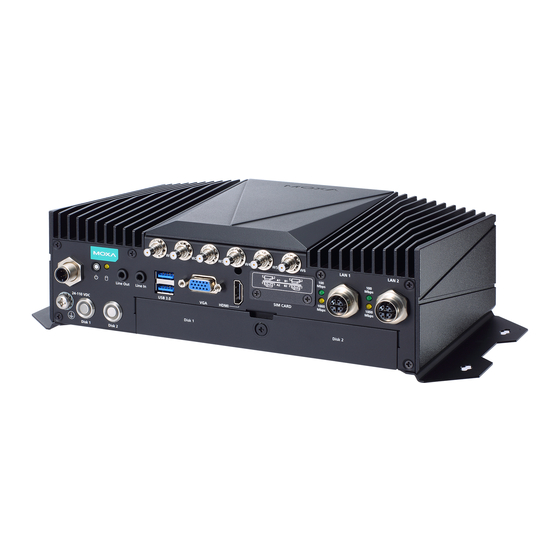
Page 9: Appearance
V2406C Hardware Hardware Introduction Appearance Front View Rear View... -
Page 10: Dimensions
V2406C Hardware Hardware Introduction Dimensions LED Indicators LED Name Status Function Power Green Power is on (on Power No power input Button) Ethernet Green Steady On: 100 Mbps Ethernet link (100 Mbps) Blinking: Data transmission is in progress (1000 Mbps) -
Page 11: Real-Time Clock
V2406C Hardware Hardware Introduction Real-time Clock The embedded computer’s real-time clock is powered by a lithium battery. We strongly recommend that you NOT replace the lithium battery on your own. If the battery needs to be changed, contact the Moxa RMA service team. -
Page 12: Hardware Connection Description
In this chapter, we show how to connect the embedded computers to the network and to a variety of common devices. The following topics are covered in this chapter: Installing the V2406C Wiring Requirements Connecting the Power ... -
Page 13: Installing The V2406C
Refer to the following illustration for details. Use two screws (M3*5L standard is recommended) per side to attach the V2406C computer to a wall or a cabinet. The product package does not include the four screws required for attaching the wall-mounting kit to the wall;... -
Page 14: Wiring Requirements
Connecting the Power Connect the 24 to 110 VDC power line with M12 connector to the V2406C computer. If the power is supplied properly, the Ready LED will glow a solid green after a 25 to 30 second delay. -
Page 15: Grounding The Unit
V2406C Hardware Hardware Connection Description Definition N.C. N.C. The power input specification is given below: • DC mains with a power source rating of 24 V @ 2.74 A; 100 V @ 0.584 A, and a minimum of 14 AWG. -
Page 16: Connecting Data Transmission Cables
There is risk of damage to the M12 X-coded cable due to improper installation or removal. Before you attach an M12 X-coded cable to an Ethernet port on the V2406C, read the instructions carefully. The M12 X-coded cable is designed with locking mechanisms to prevent pin misalignment. Make sure that you properly align the indicator and notches when connecting the cable. - Page 17 V2406C Hardware Hardware Connection Description NOTE For best performance and transmission quality, Moxa strongly recommends that you use cables and connectors from Phoenix Contact. 2. Align the notch on the M12 X-coded cable pin core with the notch on the port socket.
-
Page 18: Connecting To A Serial Device
Connecting an Audio Input and Output The V2406C comes with a Line-in and a Line-out with 35 mm jack plug connectors, allowing users to connect a speaker or an earphone. -
Page 19: Digital Input/Output
V2406C Hardware Hardware Connection Description Digital Input/Output The V2406C comes with a 6-channel digital input and a 2-channel digital output through a terminal block connector. Refer to the following figures for the pin definitions and the current ratings. Digital Inputs... -
Page 20: Connecting To A Vga Monitor
Connecting to the USB Ports The V2406C comes with four USB ports, two on the front panel, another two on the rear panel. All four ports come with USB 3.0 type A interfaces. Refer to the following illustrations for the location of these ports. -
Page 21: Installing A Hot-Swappable Storage Drive
Installing a Hot-swappable Storage Drive The V2406C comes with two storage sockets, allowing users to install two disks for data storage. Follow these steps to install a hard disk drive. Unpack the storage disk tray. -
Page 22: Installing The Sim Cards
To take out the tray, pull the clutch in the tray to your right and pull out the tray. Installing the SIM Cards The V2406C comes with 2 sockets, allowing users to install Wi-Fi or cellular modules. To install the cellular module, you need to install the SIM card first. Follow these steps. -
Page 23: Installing The Wi-Fi Module
V2406C Hardware Hardware Connection Description Inserting the SIM cards incorrectly may damage the slot and the SIM card. Check the following diagrams to confirm that the SIM card is inserted correctly into the slots. Module A1 Module A2 Module B1 Module B2 To remove the SIM card, simply push in the SIM card to release it and pull out the SIM card. - Page 24 V2406C Hardware Hardware Connection Description 2. Remove the four screws on the bottom panel of the computer. 3. Remove the screw on storage slot cover on the front panel. 4. Take out the bottom cover of the computer, and find the location of the Wi-Fi module sockets.
-
Page 25: Installing The Cellular Module
V2406C Hardware Hardware Connection Description 6. Install the metal plate and secure it with the two screws in the package. 7. Place the Wi-Fi module in the socket and 8. Place the protection cover on the antenna cable connect the antenna cables to the connectors and secure the cover with the two connectors. -
Page 26: Installing The Wireless Cables And Antennas
V2406C Hardware Hardware Connection Description Note that there are three antenna connectors on the cellular module: one for GPRS and two for cellular communication. Installing the Wireless Cables and Antennas Follow these steps to connect the wireless cables and antennas. -
Page 27: Switching The Wireless Module Socket
V2406C Hardware Hardware Connection Description b. Use an extension cord and then connect the antenna. Switching the Wireless Module Socket As there are two wireless module sockets and you can install the Wi-Fi or the cellular module on either of the sockets, a DIP switch is provided to enable selection of the Wi-Fi or cellular module. -
Page 28: Installing The Msata Drive
Insert the mSATA module into the socket, and fasten two screws to secure the module. Upgrading the Memory The V2406C comes with 2 DDR4 2400 SO-DIMM slots, with 8 GB memory preinstalled on one slot. To upgrade or replace the memory, follow these steps. - Page 29 V2406C Hardware Hardware Connection Description 2. Push the two clutches on both sides of the memory outwards and remove the memory card. 3. Insert the new memory card, pull in the clutches, and push down the memory card. 3-18...
-
Page 30: Replacing The Battery
4. Replace the cover to complete the memory upgrade and installation process. Replacing the Battery The V2406C comes with one battery slot containing a lithium battery with the specifications 3V/195 mAh. To replace the battery, do the following: 1. The battery cover is located on the front panel of the computer. - Page 31 V2406C Hardware Hardware Connection Description 4. Separate the connectors and remove the two screws on the metal plate. 5. Replace the battery, place the metal plate on the battery, and fasten the screws to secure the batteries. 6. Reconnector the connectors, place the battery into the slot, and put back the cover.
- Page 32 V2406C Hardware Hardware Connection Description NOTE Make sure you use the correct type of battery. Incorrect battery may cause system damage. Contact Moxa’s technical support staff for assistance, if necessary. NOTE This computer is intended to be installed in a restricted access area only. In addition, for safety reasons, the computer should be installed and handled only by qualified and experienced professionals.
-
Page 33: Bios Setup
BIOS Setup In this chapter, we describe the V2406C computer’s BIOS settings. The BIOS is a set of input/output control routines for peripherals. The BIOS is used to initialize basic peripherals and help boot the operating system before the operating system is loaded. The BIOS setup allows the user to modify the system configurations of these input/output peripherals. -
Page 34: Entering The Bios Setup
V2406C Hardware BIOS Setup Entering the BIOS Setup To enter the BIOS setup utility, press the F2 key while the system is booting up. The main BIOS Setup screen will appear. You can configure the following settings on this screen. -
Page 35: Main Page
V2406C Hardware BIOS Setup The BIOS configuration screen will be shown when you enter the Setup Utility option, as shown in the following figure: Note that the Processor Type information will vary depending on the model that you have purchased. -
Page 36: Advanced Settings
V2406C Hardware BIOS Setup Advanced Settings Select the Advanced tab in the main menu to open the advanced features screen. NOTE The Active Management Technology is not supported in the KL1 and KL3 models. -
Page 37: Boot Configuration
V2406C Hardware BIOS Setup Boot Configuration This item allows users to configure the default value of Numlock. Options: On (default), Off. SATA Configuration You can use this setting to select the mode for the host drive controller. Options are AHCI (default) and Intel... - Page 38 Set HDC configuration as “Intel RST Premium” to enable redundant array of inexpensive disks technology. The V2406C has three SATA interfaces, which only supports RAID levels 0, 1, 5 and Recovery. Recovery utilizes RAID 1 (mirroring) functionality to copy data from a designated master drive to a designated recovery drive.
-
Page 39: Intel Rapid Storage Technology
V2406C Hardware BIOS Setup When setting the Intel RST Premium mode, or saving changes and reboot, you can select Device Management to configure the following Intel Rapid Storage Technology. Intel Rapid Storage Technology This section allows users to configure Intel® Rapid Storage Technology. -
Page 40: Cpu Configuration
V2406C Hardware BIOS Setup CPU Configuration NOTE Hyper-Threading is not supported in the KL1 models. -
Page 41: Active Management Technology Support
V2406C Hardware BIOS Setup Active Processor Cores This item indicates the number of cores to enable in each processor package. Hyper-Threading This feature makes the processor resources work more efficiently, enabling multiple threads to run on each core. It also increases processor throughput, improving overall performance on threaded software. -
Page 42: Video Configuration
V2406C Hardware BIOS Setup Unconfigure ME on RTC Clear State Disabling this option will cause ME not to unconfigure on RTC clear. Options: Disabled, Enabled (default) Unconfigure ME Unconfigure ME by resetting the MEBx password to the default password. Video Configuration DVMT Pre-Allocated This item allows you to configure pre-allocated memory capacity for the IGD. -
Page 43: Chipset Configuration
V2406C Hardware BIOS Setup Chipset Configuration This item allows you to configure the chipset settings. Power ON after Power Failure This item allows you to enable/disable the computer from automatically powering up after system power is re-enabled. Options: ON (default), OFF, Last State DO-0 Level This item allows users to set the DO 0 as high or low. -
Page 44: Sio Ite8786E
V2406C Hardware BIOS Setup SIO ITE8786E This section allows users to configure serial port settings. Serial Port A This function allows users to configure the resources for the serial port A. Disable: No resources Enable: User configures the resources Auto (default): EFI/OS chooses the resources Serial Port B This function allows users to configure the resources for the serial port B. -
Page 45: Console Redirection
V2406C Hardware BIOS Setup Serial Port D This function allows users to configure the resources for the serial port A. Disable: No resources Enable: User configures the resources Auto (default): EFI/OS chooses the resources Hardware Monitor This item allows you to view stats such as CPU and system temperature, voltage levels, and other chipset information. -
Page 46: Security Settings
V2406C Hardware BIOS Setup Security Settings This section allows users to configure security-related settings with a supervisor password and user password. Current TPM Device This item shows if the system has TMP device and its type. TPM State This item allows you view the status of current TPM settings. -
Page 47: Set Supervisor Password
V2406C Hardware BIOS Setup Set Supervisor Password This item allows you to set the supervisor password. Select the Set Supervisor Password option and enter the password and confirm the password again. To delete the password, select the Set Supervisor Password option and enter the old password; leave the new password fields blank, and then press enter. -
Page 48: Power Settings
V2406C Hardware BIOS Setup Enable: System will ask input password on post time. Disable: System will ask for the password to go to the setup utility. Config-Only: System will only ask for the password when you select the config (F2) option Power Settings The section allows users to configure power settings. -
Page 49: Mpcie#2 Power
V2406C Hardware BIOS Setup mPCIE#2 Power This item allows you to control the power in the 2 mPCIe connector. Options: Off (default), on Boot Settings The section allows users to configure boot settings. NOTE If you do not add any storage, you will not see the EFI option. -
Page 50: Usb Boot
V2406C Hardware BIOS Setup USB Boot Set booting to USB boot devices capability. Options: Enabled (Default), Disabled Timeout This item allows users to set the number of second that the firmware will wait before booting the original default boot selection. -
Page 51: Exit Discarding Changes
V2406C Hardware BIOS Setup Exit Discarding Changes This item allows you to exit without saving any changes that might have been made to the BIOS. Options: Yes (default), No Load Optimal Defaults This item allows you to revert to the factory default BIOS values. -
Page 52: Enable Amt
V2406C Hardware BIOS Setup Enable AMT NOTE The AMT function is not supported for KL1 and KL3 models. To enter the BIOS setup utility, press the “F2” key while the system is booting up. The main BIOS Setup screen will appear. Five options will be available: 1. - Page 53 V2406C Hardware BIOS Setup 3. Type the default password: admin 4. Type the new password. It must include both upper-case and lower-case characters, numbers, and special symbols. E.g., Admin’12. 5. Select Intel® AMT Configuration to enable remote access without a local user present for consent, select User Consent, and then select User Opt-in and change the value to None.
- Page 54 V2406C Hardware BIOS Setup 6. Set static IP or DHCP by request. 7. Set Activate Network Access to enable remote access capability. 4-22...
-
Page 55: Use Amt
You can use any of the available AMT tools to execute the remote management function. The easiest method is using a web browser. 1. Type the IP for your V2406C that was configured in the AMT configuration with port 16992. The AMT logon screen will appear. -
Page 56: Upgrading The Bios
V2406C Hardware BIOS Setup Upgrading the BIOS This section describes how to upgrade the BIOS. However, note that it is easy to permanently damage the computer when upgrading the BIOS. We strongly recommend that you contact Moxa’s technical support staff for assistance in order to obtain all the necessary tools and the most current advice before attempting to upgrade the BIOS on any Moxa device. - Page 57 V2406C Hardware BIOS Setup 2. Right click on the USB disk then select “Format”. 3. Select “FAT32”, and click OK to start formatting. Step 2: Prepare the Upgrade File You must use the BIOS upgrade installation file to upgrade the BIOS. Contact Moxa’s technical department for assistance.
- Page 58 V2406C Hardware BIOS Setup Step 3: Run the upgrade program on the Computer 1. Reboot the computer, and press F2 while booting up to go to the Boot Manager. If BIOS cannot recognize the USB drive as the boot devices, the USB drive could have no partition table. Use windows command line tool diskpart to rebuild the partition table.
- Page 59 V2406C Hardware BIOS Setup 5. When the upgrade is finished, the computer will automatically reboot. You may check BIOS version on the Main page 6. If the system has more than one boot device, you will see more than one fsx (x represents the number).
-
Page 60: Regulatory Approval Statement
Regulatory Approval Statement This device complies with part 15 of the FCC Rules. Operation is subject to the following two conditions: (1) This device may not cause harmful interference, and (2) this device must accept any interference received, including interference that may cause undesired operation.
Need help?
Do you have a question about the V2406C and is the answer not in the manual?
Questions and answers