Moxa Technologies V2406A Series Hardware User Manual
Embedded computers
Hide thumbs
Also See for V2406A Series:
- Quick installation manual (2 pages) ,
- Instruction manual (22 pages)

Related Manuals for Moxa Technologies V2406A Series


Summary of Contents for Moxa Technologies V2406A Series
- Page 1 V2406A Hardware User’s Manual Edition 3.0, February 2017 www.moxa.com/product © 2017 Moxa Inc., All rights reserved.
-
Page 2: Copyright Notice
V2406A Hardware User’s Manual The software described in this manual is furnished under a license agreement and may be used only in accordance with the terms of that agreement. Copyright Notice © 2017 Moxa Inc. All rights reserved. Trademarks The MOXA logo is a registered trademark of Moxa Inc. All other trademarks or registered marks in this manual belong to their respective manufacturers. -
Page 3: Table Of Contents
Table of Contents Introduction ............................1-1 Package Checklist ..........................1-2 Product Features ..........................1-2 V2406A Hardware Specifications ......................1-2 Hardware Block Diagram ........................1-5 Hardware Introduction ........................2-1 Appearance ............................2-2 Dimensions (unit = mm) ........................2-3 LED Indicators ............................ 2-3 Reset Button ............................ -
Page 5: Introduction
Introduction The V2406A series embedded computers are based on the Intel 3rd-generation processor and feature four RS-232/422/485 serial ports, dual Gigabit Ethernet ports, audio in/out, three USB 2.0 hosts, two CFast sockets, and one SATA storage socket. In addition, the V2406A computers have dual DVI-I outputs, and are compliant with a portion of EN 50155 covering operating temperature, power input voltage, power surge, ESD, and vibration, making them particularly well-suited for railway applications. -
Page 6: Package Checklist
V2406A Hardware Introduction Package Checklist Each model is shipped with the following items: • V2406A series embedded computer • Wall mounting kit • Documentation and software CD or DVD • Quick installation guide (printed) • Warranty card NOTE: Please notify your sales representative if any of the above items are missing or damaged. - Page 7 V2406A Hardware Introduction Ethernet Interface LAN: 2 auto-sensing 10/100/1000 Mbps ports (M12 X-coded) Isolation Protection: 1.5 kV Serial Interface Serial Standards: 4 RS-232/422/485 ports, software selectable (DB9 male) ESD Protection: 4 kV for all signals Isolation Protection: 1.5 kV Serial Communication Parameters Data Bits: 5, 6, 7, 8 Stop Bits: 1, 1.5, 2 Parity: None, Even, Odd, Space, Mark...
-
Page 8: Power Requirements
V2406A Hardware Introduction *without HDD installed Ambient Relative Humidity: 5 to 95% (non-condensing) Anti-Vibration: EN 50155 standard Anti-Shock: EN 50155 standard Conformal Coating: Available on request Power Requirements Input Voltage: 12 to 48 VDC (M12 A-coded) Note: Compliant with EN 50155 at 24 VDC Power Consumption: •... -
Page 9: Hardware Block Diagram
V2406A Hardware Introduction Hardware Block Diagram... -
Page 10: Hardware Introduction
Hardware Introduction The V2406A series embedded computers are compact, well-designed, and rugged enough for industrial applications. LED indicators help you monitor performance and identify trouble spots, multiple serial ports allow you to connect different devices for wireless operation, and the reliable and stable hardware platform lets you devote your attention to developing your applications. -
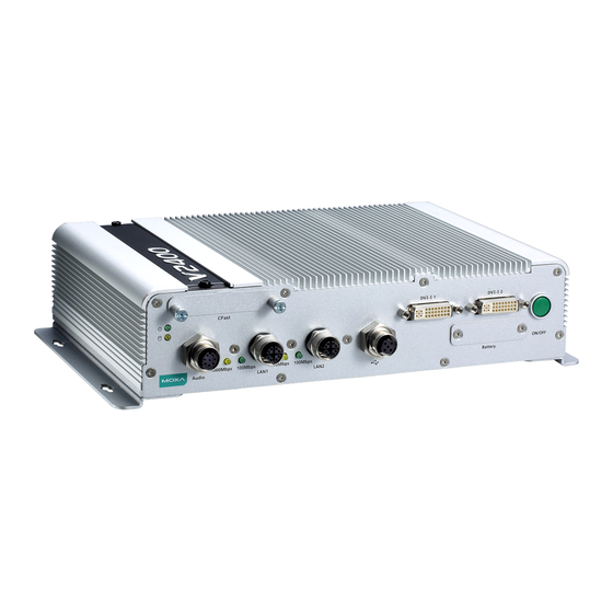
Page 11: Appearance
V2406A Hardware Hardware Introduction Appearance Front View Rear View... -
Page 12: Dimensions (Unit = Mm)
V2406A Hardware Hardware Introduction Dimensions (unit = mm) LED Indicators LED Name LED Color LED Function Power Green Power is on and functioning normally. Power is off or power error exists. Storage Yellow CFast card/HDD/SSD is transmitting data. CFast card/HDD/SSD is not transmitting data. LAN (1 or 2) Green 100 Mbps Ethernet mode. -
Page 13: Reset Button
V2406A Hardware Hardware Introduction Reset Button Press the Reset Button on the rear panel of the V2406A to reboot the system automatically. The Ready LED will blink on and off for the first 5 seconds, and then maintain a steady glow once the system has rebooted. The V2406A does not support a “Reset to Default”... -
Page 14: Hardware Connection Description
Hardware Connection Description In this chapter, we show how to connect the embedded computers to the network and to various devices. The following topics are covered in this chapter: Installing theV2406A Wiring Requirements Connecting the Power Grounding the Unit ... -
Page 15: Installing Thev2406A
V2406A Hardware Hardware Connection Description Installing theV2406A Wall or Cabinet Mounting The V2406A comes with two metal brackets for attaching the device on a wall or to the inside of a cabinet. Complete the following steps to attach the mounting brackets to the V2406A. Step 1: Use two screws for each bracket to attach the brackets to the rear of the V2406A. - Page 16 V2406A Hardware Hardware Connection Description To attach the DIN-rail kit, complete the following steps: 1. Turn the V2406A over so the bottom is facing up. 2. Locate the screw holes on the bottom of the V2406A. 3. Place the brackets on the bottom of the V2406A and align the screw holes on the brackets with the screw holes on the V2406A.
-
Page 17: Wiring Requirements
V2406A Hardware Hardware Connection Description To re-install the V2406A on the DIN rail, use a screwdriver to press the buckle so that it can be released. At this point, it can be re-installed on the DIN rail. Wiring Requirements In this section, we describe how to connect serial devices to the V2406A embedded computer. Be sure to read and follow these common safety precautions before proceeding with the installation of any electronic device: •... -
Page 18: Connecting The Power
V2406A Hardware Hardware Connection Description ATTENTION Safety First! Be sure to disconnect the power cord before installing and/or wiring your V2406A. Wiring Caution! Calculate the maximum possible current in each power wire and common wire. Observe all electrical codes dictating the maximum current allowable for each wire size. If the current goes above the maximum ratings, the wiring could overheat, causing serious damage to your equipment. -
Page 19: Connecting To A Serial Device
V2406A Hardware Hardware Connection Description Connecting to a Serial Device Use a serial cable to connect your serial device to the embedded computer’s serial port. Serial ports P1 to P4 have male DB9 connectors and can be configured for RS-232, RS-422, or RS-485 communication (refer to the software manual for your operating system version). -
Page 20: Connecting To A Usb Device
V2406A Hardware Hardware Connection Description ATTENTION Make sure that you orient the CFast card properly before pushing it into the slot. The bottom of the CFast card must be facing up for the card to work properly, and for the CFast socket cover to be installed properly. 4. -
Page 21: Di/Do
V2406A Hardware Hardware Connection Description DI/DO The V2406A comes with a 6-ch digital input and a 2-ch digital output that connect through a terminal block connector. The pin assignments and wiring methods are shown below. DI Wiring: Dry Contact DI Wiring: Wet Contact DO Wiring: Dry Contact... -
Page 22: Connecting To A Dvi-I Monitor
V2406A Hardware Hardware Connection Description Connecting to a DVI-I Monitor The V2406A computers come with a DVI-I connector that you can connect to a DVI monitor. Use the cable to connect one end to the DVI-I connector on the V2406A and the other end to the monitor. The following table lists the DVI-I connector pin assignments. -
Page 23: Connecting To A Speaker Or A Headphone
V2406A Hardware Hardware Connection Description Connecting to a Speaker or a Headphone The V2406A comes with an M12 A-coded audio connector for connecting a microphone and speaker or headphones. See the following figure for details. Installing a SATA Hard Disk The V2406A has one SATA-I/II connector for 2.5"... - Page 24 V2406A Hardware Hardware Connection Description 2. Make sure that the V2406A is turned off and is disconnected from its power source. 3. The RTC battery socket is located to the left of the “ON/OFF” power button, below the “DVI-I 2” connector. Loosen two screws used to attach the RTC battery socket cover to the V2406A.
- Page 25 V2406A Hardware Hardware Connection Description 5. Disconnect the power cable between the battery and the V2406, and then connect the new RTC Battery Kit to the V2406A. 6. Slide the battery holder back into the RTC battery socket and then fasten the socket cover to the V2406A using the screws you removed in Step 3 above.
-
Page 26: Bios Setup
BIOS Setup In this chapter, we describe the BIOS settings for the V2406A embedded computer. The BIOS is a set of input/output control routines for peripherals. The BIOS is used to initialize basic peripherals and helps boot the operating system before the operating system is loaded. The BIOS setup allows the user to modify the system configurations of these basic input/output peripherals. -
Page 27: Entering The Bios Setup
V2406A Hardware BIOS Setup Entering the BIOS Setup To enter the BIOS setup utility, press the F2 key while the system is booting up. The main BIOS Setup screen appears with the following options: Continue: Continue to boot up • •... -
Page 28: Main Information
V2406A Hardware BIOS Setup Main Information The main page shows basic system information, such as the model name, BIOS version, and CPU type. NOTE The “Processor Type” varies depending on the product model. Advanced Settings The Advanced screen appears when you select “Advanced” from the main menu. -
Page 29: Boot Configuration
V2406A Hardware BIOS Setup Boot Configuration This screen allows you to configure the initial status of the Numlock key when the computer boots up. Options: On (default), Off HDC Configuration The host drive controller can be configured in IDE or AHCI (default) mode. When you select the AHCI mode, the following screen appears. -
Page 30: Video Configuration
V2406A Hardware BIOS Setup AHCI SALP Note that the “AHCI SALP” setting only appears when you select the AHCI mode. This setting allows you to enable aggressive link power management (SALP) in AHCI. SALP enables the host bus adapter to conserve power by directly detecting when a SATA drive is no longer processing information and then immediately transition the drive into suspended or sleep mode without waiting for software processes to initiate a power-down process. - Page 31 V2406A Hardware BIOS Setup Internal Graphics Device This screen allows you to enable or disable the internal graphics device. IGD—DVMT Pre-Allocated This setting allows you to configure the pre-allocated memory capacity of the IGD. Pre-allocated graphics memory is invisible to the operating system. Options: 64 MB (default), 32 MB, 96 MB, 128 MB, 256 MB, 512 MB DVMT is a BIOS solution where the optimum amount of memory is dynamically allocated and de-allocated as needed for balanced graphics and system performance, through Intel®...
-
Page 32: Chipset Configuration
V2406A Hardware BIOS Setup Chipset Configuration This screen allows you to configure the chipset settings. Power ON after Power Fail This setting allows you to configure whether or not the computer automatically powers up after a system crash. When set to ON, the computer will automatically power up after a system crash; when set to OFF, it won’t automatically power up after a system crash. -
Page 33: Hardware Monitor
V2406A Hardware BIOS Setup Hardware Monitor This screen allows you to view voltage levels, system temperature, and CPU temperature. Note that the voltage values vary depending on the model. The temperature readings shown on the screen are within ±5% of the actual readings. However, the temperature readings are only valid when the ambient temperature is above 0°C. -
Page 34: Smart Recovery Info
V2406A Hardware BIOS Setup SMART RECOVERY Info This screen allows you to view Smart Recovery information. Load SMART RECOVERY Default This setting allows you to load the Smart Recovery default value. Refer to the Smart Recovery Website at http://www.moxa.com/product/Smart-Recovery.htm for details Options: Yes (default), No Security Settings This screen allows you to configure a supervisor password. -
Page 35: Set Supervisor Password
V2406A Hardware BIOS Setup Set Supervisor Password This setting allows you set the supervisor password. Type the new password, and then retype the password again to confirm. To delete the password, enter the existing password in the Set Supervisor Password field and leave the new password fields blank;... -
Page 36: Auto Wake On S5
V2406A Hardware BIOS Setup Auto Wake on S5 This setting allows you to configure the computer to wake from the S5 (Soft Off) state where the power supply remains engaged but is not supplying power to all other parts of the system. You can set the auto-wake on S5 schedules for the system to perform a soft-reboot at specific times. -
Page 37: Wake On Lan
V2406A Hardware BIOS Setup Wake on LAN This setting allows you to wake the system over the LAN from a remote host. Options: Enabled (default), Disabled. Boot Settings The screen allows you to configure boot settings. Boot Type This setting allows you to enable or disable the quick boot function. Options: Dual Boot Type (default), Legacy Boot Type, UEFI Boot Type PXE Boot to LAN This setting allows you to enable or disable the PXE boot to LAN function. -
Page 38: Usb Boot
V2406A Hardware BIOS Setup USB Boot This setting allows you to enable or disable the USB boot function. Options: Enabled (default), Disabled EFI Device First This setting allows you to determine the booting priority of the EFI device. If this setting is enabled, the EFI device will boot first;... -
Page 39: Exit Settings
V2406A Hardware BIOS Setup Hard Disk Drive/USB Drive This setting allows you to view the installed devices, such as hard disk drives, USB drives, and CD-ROMs. For example, if you have inserted a USB drive into the computer, the USB drive entry is listed here. You can view and select the boot order for the same type of storage devices. -
Page 40: Exit Saving Changes
V2406A Hardware BIOS Setup Exit Saving Changes This option allows you to exit the BIOS setup utility and save the values you have just configured. Options: Yes (default), No Save Change Without Exit This option allows you to save changes without exiting the BIOS setup utility. Options: Yes (default), No Exit Discarding Changes This option allows you to exit without saving that changes that might have been made to the BIOS. -
Page 41: Upgrading The Bios
V2406A Hardware BIOS Setup Upgrading the BIOS This section describes how to upgrade the BIOS. WARNING An improper BIOS upgrade process may permanently damage the computer. We strongly recommend that you contact Moxa technical support for assistance to obtain all the necessary tools and the most up-to-date advice before attempting to upgrade the BIOS on any Moxa device. - Page 42 V2406A Hardware BIOS Setup Step 3: Run the Upgrade Program on the V2406A Computer 1. Reboot the computer, and press F2 during the booting process to display the Boot Manager. 2. Select USB Disk as the first boot source and press [Enter] to continue. 3.
- Page 43 V2406A Hardware BIOS Setup 5. The upgrade program will run automatically. Wait until the procedure is complete. ATTENTION Do NOT remove the power supply during a BIOS upgrade. C:\>V2400A\24A10S05.exe Reading file… Flash package mode. Option: -BIOS –C –Desc –ME Please do not remove the AC power! Insyde Flash Utility for InsydeH20 Version 1.5t Initializing...
-
Page 44: Regulatory Approval Statement
Regulatory Approval Statement This device complies with part 15 of the FCC Rules. Operation is subject to the following two conditions: (1) This device may not cause harmful interference, and (2) this device must accept any interference received, including interference that may cause undesired operation.
Need help?
Do you have a question about the V2406A Series and is the answer not in the manual?
Questions and answers