
Related Manuals for Moxa Technologies V2403 Series


Summary of Contents for Moxa Technologies V2403 Series
- Page 1 V2403 Series Quick Installation Guide Version 2.1, January 2021 Technical Support Contact Information www.moxa.com/support 2021 Moxa Inc. All rights reserved. P/N: 1802024030012 *1802024030012*...
-
Page 2: Package Checklist
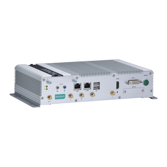
Overview The Moxa V2403 series fanless x86 embedded computer is based on the Intel® 3rd gen Core-i™ series processor, features the most reliable I/O design to maximize connectivity, and supports dual wireless modules, making it suitable for a diverse range of communication applications. The computer’s thermal design ensures reliable system operation in... - Page 3 LED Indicators The following table describes the LED indicators located on the front panel of the V2403. LED Name LED Color LED Function Power Green Power is on and functioning normally. Power is off or power error exists. Storage Yellow CFast card/HDD/SSD is transmitting data CFast card/HDD/SSD is not transmitting data LAN (1 or 2)
- Page 4 Installing a mini-PCIe Card in Socket 1 and Socket 3 STEP 1: Loosen the 6 screws in the middle of the bottom cover and then open the bottom cover. STEP 2: Obliquely insert the mini-PCIe module card. STEP 3: Push down the mini-PCIe module card and fasten it with the 2 black screws from the module card package you purchased from Moxa.
- Page 5 STEP 4: Connect the antenna cables to the wireless module card: No. 2 & No. 4: 3G/LTE mini-PCIe card No. 5: GPS STEP 5: Use the fillister to obliquely buckle the heat sink that was already installed inside the V2403 computer, as shown below: ...
- Page 6 NOTE You may also purchase 3G, 4G, and Wi-Fi external antennas from from Moxa. Please contact Moxa sales representative for your demand. Installing the V2403 DIN-Rail Mounting The V2403 can be installed on a DIN-rail with the optional DIN-rail kit. The DIN-rail kit must be purchased separately.
- Page 7 To remove the V2403 from the DIN-rail, first use a screwdriver to pull down the DIN-rail connector to unlock it. To re-install the V2403 on the DIN-rail, use a screwdriver to press the buckle so that it can be released. At this point, it can be re-installed on the DIN-rail.
-
Page 8: Connector Description
Connector Description Power Connector Connect the 9 to 36 VDC LPS or Class 2 power line to the V2403’s terminal block. If the power is supplied properly, the Power LED will light up. The OS is ready when the Ready LED glows a solid green. Grounding the V2403 Grounding and wire routing help limit the effects of noise due to electromagnetic interference (EMI). - Page 9 Ethernet Ports The 10/100/1000 Mbps Ethernet ports use RJ45 connectors. 10/100 Mbps 1000 Mbps ETx+ TRD(0)+ ETx- TRD(0)- ERx+ TRD(1)+ – TRD(2)+ – TRD(2)- ERx- TRD(1)- – TRD(3)+ – TRD(3)- Serial Ports The serial ports use DB9 connectors. Each port can be configured by software for RS-232, RS-422, or RS-485.
- Page 10 Audio Interface The V2403 comes with a Line-in audio connector for audio input and a Line-out audio connector for audio output, allowing users to connect a speaker or earphones. DI/DO The V2403 comes with 4 digital inputs and 4 digital outputs on a 2x5 terminal block.
-
Page 11: Configuring The Ethernet Interface
Connecting the V2403 to a PC Power on the V2403 computer after connecting a monitor, keyboard, and mouse, and verifying that the power source is ready. Once the operating system boots up, first configure the Ethernet interface. The factory default settings for the V2403’s LANs are show below (W7E uses DHCP). Default IP Address Netmask LAN 1...
Need help?
Do you have a question about the V2403 Series and is the answer not in the manual?
Questions and answers