
Related Manuals for Moxa Technologies V2403 Series


Summary of Contents for Moxa Technologies V2403 Series
- Page 1 V2403 Series Hardware User’s Manual Edition 2.0, February 2017 www.moxa.com/product © 2017 Moxa Inc., All rights reserved.
- Page 2 V2403 Series Hardware User’s Manual The software described in this manual is furnished under a license agreement and may be used only in accordance with the terms of that agreement. Copyright Notice © 2017 Moxa Inc., All rights reserved. Trademarks The MOXA logo is a registered trademark of Moxa Inc.
-
Page 3: Table Of Contents
Table of Contents Introduction ............................1-1 Package Checklist ..........................1-2 Product Features ..........................1-2 V2403 Hardware Specifications......................1-2 Hardware Block Diagram ........................1-5 Hardware Introduction ........................2-1 Appearance ............................2-2 Dimensions ............................2-3 LED Indicators ............................ 2-3 Reset Button ............................2-4 Real Time Clock (RTC) ......................... -
Page 5: Introduction
Introduction The Moxa V2403 series fanless x86 embedded computer is based on the Intel® 3rd gen Core-i™ series processor, features the most reliable I/O design to maximize connectivity, and supports dual wireless modules, making it suitable for a diverse range of communication applications. The computer’s thermal design ensures reliable system operation in temperatures ranging from -40 to 70°C with a special purpose Moxa wireless... -
Page 6: Package Checklist
V2403 Series Hardware Introduction Package Checklist Each model is shipped with the following items: • V2403 series embedded computer • Wall mounting kit • Terminal block to power jack converter • Documentation and software CD or DVD • Quick installation guide (printed) •... - Page 7 V2403 Series Hardware Introduction Display Graphics Controller: Intel® HD (integrated) Connector Type: 1 HDMI connector (type A), 1 DVI-I connector, 1 VGA connector (CV required) Display Interface: HDMI supports HDMI 1.4b, 1920 x1200 resolution @ 60 Hz • DVI up to 1920x1200 resolution @ 60 Hz •...
- Page 8 V2403 Series Hardware Introduction Physical Characteristics Housing: Aluminum Weight: "-W" Models: 2.247 kg non "-W" Models: 2.168 kg Dimensions: Without ears: 250 x 57 x 154 mm (9.84 x 2.23 x 6.06 in) With ears: 275 x 63 x 154 mm (10.83 x 2.47 x 6.06 in)
-
Page 9: Hardware Block Diagram
V2403 Series Hardware Introduction Hardware Block Diagram... -
Page 10: Hardware Introduction
Hardware Introduction The V2403 series embedded computers are compact, well-designed, and rugged enough for industrial applications. LED indicators help you monitor performance and identify trouble spots, multiple serial ports allow you to connect different devices for wireless operation, and the reliable and stable hardware platform lets you devote your attention to developing your applications. -
Page 11: Appearance
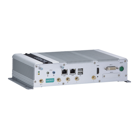
V2403 Series Hardware Hardware Introduction Appearance Front View Rear View... -
Page 12: Dimensions
V2403 Series Hardware Hardware Introduction Dimensions LED Indicators LED Name LED Color LED Function Power Green Power is on and functioning normally. Power is off or power error exists. Storage Yellow CFast card/HDD/SSD/mSATA is transmitting data. CFast card/HDD/SSD/mSATA is not transmitting data. -
Page 13: Reset Button
V2403 Series Hardware Hardware Introduction Reset Button Press the “Reset Button” on the rear panel of the computer to reboot the system automatically. Pushing the reset button will restart the system immediately, and any unsaved data will be lost. The V2403 does not support a “Reset to Default” function. -
Page 14: Hardware Connection Description
Hardware Connection Description In this chapter, we show how to connect the embedded computers to the network and to various devices. The following topics are covered in this chapter: Installing theV2403 Wiring Requirements Connecting the Power Grounding the Unit ... -
Page 15: Installing Thev2403
V2403 Series Hardware Hardware Connection Description Installing theV2403 Wall or Cabinet Mounting The V2403 comes with two metal brackets for attaching the device on a wall or to the inside of a cabinet. Complete the following steps to attach the mounting brackets to the V2403. - Page 16 V2403 Series Hardware Hardware Connection Description To attach the DIN-rail kit, complete the following steps: 1. Turn the V2403 over so the bottom is facing up. 2. Locate the screw holes on the bottom of the V2403. 3. Place the brackets on the bottom of the V2403 and align the screw holes on the brackets with the screw holes on the V2403.
-
Page 17: Wiring Requirements
V2403 Series Hardware Hardware Connection Description To re-install the V2403 on the DIN rail, use a screwdriver to press the buckle so that it can be released. At this point, it can be re-installed on the DIN rail. Wiring Requirements In this section, we describe how to connect serial devices to the V2403 embedded computer. -
Page 18: Grounding The Unit
V2403 Series Hardware Hardware Connection Description Grounding the Unit Grounding and wire routing help limit the effects of noise due to electromagnetic interference (EMI). Run the ground connection from the grounding screw (M5) to the grounding surface prior to connecting the power. - Page 19 V2403 Series Hardware Hardware Connection Description Installing a mini-PCIe Card in Socket 1 and Socket 3 STEP 1: Loosen the 6 screws in the middle of the bottom cover and then open the bottom cover. STEP 2: Obliquely insert the mini-PCIe module card.
- Page 20 V2403 Series Hardware Hardware Connection Description STEP 2: Get the upper heat sink cover from the wireless package. STEP 3: Obliquely insert the mini-PCIe module card in socket 2, and fasten it with the 2 black screws from the wireless package.
- Page 21 V2403 Series Hardware Hardware Connection Description STEP 5: Use the fillister to obliquely buckle the heat sink that was already installed inside the V2403 computer, as shown below: STEP 6: Slightly push down the upper heat sink cover and use the silver screw from the wireless package to fasten the upper heat sink cover (outlined in red below).
-
Page 22: Connecting To The Network
V2403 Series Hardware Hardware Connection Description Connecting to the Network Connect your network cable to the embedded computer’s Ethernet port. The other end of the cable should be connected to your Ethernet network. When the cable is properly connected, the LEDs on the embedded computer’s Ethernet port turns on to indicate a valid connection. -
Page 23: Installing A Cfast Card
V2403 Series Hardware Hardware Connection Description DB9 Male Port RS-232/422/485 Pinouts RS-485 RS-485 RS-232 RS-422 (4-wire) (2-wire) TxDA(-) TxDA(-) – TxDB(+) TxDB(+) – RxDB(+) RxDB(+) DataB(+) RxDA(-) RxDA(-) DataA(-) – – – – – – – – – Installing a CFast Card The V2403 embedded computers come with a CFast socket. -
Page 24: Di/Do
V2403 Series Hardware Hardware Connection Description DI/DO The V2403 comes with a 4-ch digital input and a 4-ch digital output that connect through a terminal block connector. The pin assignments and wiring methods are shown below. DI Dry Contact DI Wet Contact... -
Page 25: Connecting To A Dvi-I Monitor
V2403 Series Hardware Hardware Connection Description Connecting to a DVI-I Monitor The V2403 computers come with a DVI-I connector that you can connect to a DVI monitor. Use the cable to connect one end to the DVI-I connector on the V2403’s front panel and the other end to the monitor. -
Page 26: Connecting To A Vga Monitor
V2403 Series Hardware Hardware Connection Description The lock appears as shown below: The lock should appear as follows after it is attached to the V2403: Connecting to a VGA Monitor The V2403 can support VGA output; contact your Moxa sales representative for details. -
Page 27: Rtc Battery Replacement
V2403 Series Hardware Hardware Connection Description RTC Battery Replacement The V2403 embedded computer has an easy RTC battery replacement design. WARNING There is a risk of explosion if the battery is replaced by an incorrect type of battery. Consult with a qualified Moxa support engineer if you have any questions or are unclear about any these instructions. - Page 28 V2403 Series Hardware Hardware Connection Description 6. Slide the battery holder back into the RTC battery socket and then fasten the socket cover to the V2403 using the screws you removed in Step 3 above. 3-15...
-
Page 29: Bios Setup
BIOS Setup In this chapter, we describe the BIOS settings for the V2403 embedded computer. The BIOS is a set of input/output control routines for peripherals, and is used to initialize basic peripherals and help boot the operating system before the operating system is loaded. The BIOS setup allows the user to modify the system configurations of these basic input/output peripherals. -
Page 30: Entering The Bios Setup
V2403 Series Hardware BIOS Setup Entering the BIOS Setup To enter the BIOS setup utility, press the F2 key while the system is booting up. The main BIOS Setup screen appears with the following options: • Continue: Continue to boot up •... -
Page 31: Main Information
V2403 Series Hardware BIOS Setup Main Information The main page shows basic system information, such as the model name, BIOS version, and CPU type. NOTE The “Processor Type” varies depending on the product model. Advanced Settings The Advanced screen appears when you select “Advanced” from the main menu. -
Page 32: Boot Configuration
V2403 Series Hardware BIOS Setup Boot Configuration This screen allows you to configure the initial status of the Numlock key when the computer boots up. Options: On (default), Off HDC Configuration The host drive controller can be configured in IDE or AHCI (default) mode. -
Page 33: Video Configuration
V2403 Series Hardware BIOS Setup AHCI SALP Note that the “AHCI SALP” setting only appears when you select the AHCI mode. This setting allows you to enable aggressive link power management (SALP) in AHCI. SALP enables the host bus adapter to conserve... - Page 34 V2403 Series Hardware BIOS Setup Internal Graphics Device This screen allows you to enable or disable the internal graphics device. IGD—DVMT Pre-Allocated This setting allows you to configure the pre-allocated memory capacity of the IGD. Pre-allocated graphics memory is invisible to the operating system.
-
Page 35: Chipset Configuration
V2403 Series Hardware BIOS Setup Chipset Configuration This screen allows you to configure the chipset settings. Power ON after Power Fail This setting allows you to configure whether or not the computer automatically powers up after a system crash. When set to ON, the computer will automatically power up after a system crash; when set to OFF, it won’t automatically power up after a system crash. -
Page 36: Hardware Monitor
V2403 Series Hardware BIOS Setup Hardware Monitor This screen allows you to view voltage levels, system temperature, and CPU temperature. Note that the voltage values vary depending on the model. The temperature readings shown on the screen are within ±5% of the actual readings. However, the temperature readings are only valid when the ambient... -
Page 37: Smart Recovery Info
V2403 Series Hardware BIOS Setup SMART RECOVERY Info This screen allows you to view Smart Recovery information. Load SMART RECOVERY Default This setting allows you to load the Smart Recovery default value. Refer to the Smart Recovery Website at http://www.moxa.com/product/Smart-Recovery.htm... -
Page 38: Set Supervisor Password
V2403 Series Hardware BIOS Setup Set Supervisor Password This setting allows you set the supervisor password. Type the new password, and then retype the password again to confirm. To delete the password, enter the existing password in the Set Supervisor Password field and leave the new password fields blank;... -
Page 39: Turbo Mode
V2403 Series Hardware BIOS Setup Turbo Mode This field is only for models with an Intel Core-i7 processor. This field allows you to determine whether to enable the Intel CPU Turbo Boost technology. Options: Enabled (default), Disabled. 4-11... -
Page 40: Auto Wake On S5
V2403 Series Hardware BIOS Setup Auto Wake on S5 This setting allows you to configure the computer to wake from the S5 (Soft Off) state where the power supply remains engaged but is not supplying power to all other parts of the system. -
Page 41: Wake On Lan
V2403 Series Hardware BIOS Setup Wake on LAN This setting allows you to wake the system over the LAN from a remote host. Options: Enabled (default), Disabled. Boot Settings The screen allows you to configure boot settings. Boot Type This setting allows you to enable or disable the quick boot function. -
Page 42: Usb Boot
V2403 Series Hardware BIOS Setup USB Boot This setting allows you to enable or disable the USB boot function. Options: Enabled (default), Disabled EFI Device First This setting allows you to determine the booting priority of the EFI device. If this setting is enabled, the EFI device will boot first;... -
Page 43: Exit Settings
V2403 Series Hardware BIOS Setup Hard Disk Drive/USB Drive This setting allows you to view the installed devices, such as hard disk drives, USB drives, and CD-ROMs. For example, if you have inserted a USB drive into the computer, the USB drive entry is listed here. -
Page 44: Exit Saving Changes
V2403 Series Hardware BIOS Setup Exit Saving Changes This option allows you to exit the BIOS setup utility and save the values you have just configured. Options: Yes (default), No Save Change Without Exit This option allows you to save changes without exiting the BIOS setup utility. -
Page 45: Upgrading The Bios
V2403 Series Hardware BIOS Setup Upgrading the BIOS This section describes how to upgrade the BIOS. WARNING An improper BIOS upgrade process may permanently damage the computer. We strongly recommend that you contact Moxa technical support for assistance to obtain all the necessary tools and the most up-to-date advice before attempting to upgrade the BIOS on any Moxa device. - Page 46 V2403 Series Hardware BIOS Setup Step 3: Run the Upgrade Program on the V2403 Computer 1. Reboot the computer, and press F2 during the booting process to display the Boot Manager. 2. Select USB Disk as the first boot source and press [Enter] to continue.
- Page 47 V2403 Series Hardware BIOS Setup 5. The upgrade program will run automatically. Wait until the procedure is complete. ATTENTION Do NOT remove the power supply during a BIOS upgrade. C:\>V2403\ 24A12S01.exe Reading file… Flash package mode. Option: -BIOS –C –Desc –ME...
-
Page 48: Regulatory Approval Statement
Regulatory Approval Statement This device complies with part 15 of the FCC Rules. Operation is subject to the following two conditions: (1) This device may not cause harmful interference, and (2) this device must accept any interference received, including interference that may cause undesired operation.
Need help?
Do you have a question about the V2403 Series and is the answer not in the manual?
Questions and answers