
Related Manuals for Moxa Technologies V2401


Summary of Contents for Moxa Technologies V2401
- Page 1 V2401/2402 Hardware User’s Manual Fourth Edition, September 2011 www.moxa.com/product © 2011 Moxa Inc. All rights reserved. Reproduction without permission is prohibited.
-
Page 2: Copyright Notice
Information in this document is subject to change without notice and does not represent a commitment on the part of Moxa. Moxa provides this document as is, without warranty of any kind, either expressed or implied, including, but not limited to, its particular purpose. Moxa reserves the right to make improvements and/or changes to this manual, or to the products and/or the programs described in this manual, at any time. -
Page 3: Table Of Contents
Table of Contents Introduction ............................1-1 Overview ............................1-2 Package Checklist ..........................1-2 Product Features ..........................1-3 V2401/2402 Hardware Specifications ....................1-3 Hardware Block Diagram ........................1-5 Hardware Introduction........................2-1 Appearance ............................2-2 Dimensions ............................2-2 LED Indicators ............................ 2-3 Reset Button ............................ - Page 4 Power ..............................4-9 ACPI Suspend Type ........................4-10 Soft-Off by PWR-BTTN ....................... 4-10 Hardware Monitor ..........................4-10 CPU Warning Temperature ......................4-10 Warning Beep ........................... 4-10 Load Defaults ........................... 4-11 Load System Default Settings ..................... 4-11 Load System Turbo Settings ....................... 4-11 Load CMOS from BIOS .......................
-
Page 5: Introduction
VGA and DVI outputs, making them particularly well-suited for industrial applications such as SCADA and manufacturing automation. The V2401 and V2402 come with four RS-232/422/485 serial ports, and the V2401 has an additional eight RS-232 ports, making them ideal for connecting a wide range of serial devices. The dual 10/100/1000 Mbps Ethernet ports offer a reliable solution for network redundancy, promising continuous operations for data communication and management. -
Page 6: Overview
Introduction Overview The V2401 and V2402 come with four RS-232/422/485 serial ports, and the V2401 has an additional eight RS-232 ports, making them ideal for connecting a wide range of serial devices, and the dual 10/100/1000 Mbps Ethernet ports offer a reliable solution for network redundancy, promising continuous operations for data communication and management. -
Page 7: Product Features
V2401/2402 series embedded computers have the following features: • DDR2 SODIMM socket, supporting DDR2 533 up to 2 GB (max.) • Dual independent display (VGA, DVI, LVDS selectable) (V2401: VGA, DVI and LVDS; V2402: VGA and DVI) • Gigabit Ethernet ports •... -
Page 8: Digital Input
V2401/2402 HW User's Manual Introduction Serial Communication Parameters Data Bits: 5, 6, 7, 8 Stop Bits: 1, 1.5, 2 Parity: None, Even, Odd, Space, Mark Flow Control: RTS/CTS, XON/XOFF, ADDC® (automatic data direction control) for RS-485 Baudrate: 50 bps to 921.6 Kbps (non-standard baudrates supported; see user's manual for details) -
Page 9: Hardware Block Diagram
V2401/2402 HW User's Manual Introduction Power Consumption: 26 W (without LVDS output) 2.9 A @ 9 VDC 1.08 A @ 24 VDC 720 mA @ 36 VDC Standards and Certifications Safety: UL 508, UL 60950-1, CSA C22.2 No. 60950-1-07, EN 60950-1, CCC (GB9254, GB17625.1) -
Page 10: Hardware Introduction
Hardware Introduction The V2401/2402 series embedded computers are compact, well-designed, and built rugged enough for industrial applications. LED indicators help you monitor performance and identify trouble spots, multiple serial ports allow you to connect different devices for wireless operation, and the reliable and stable hardware platform lets you devote your attention to developing your applications. -
Page 11: Appearance
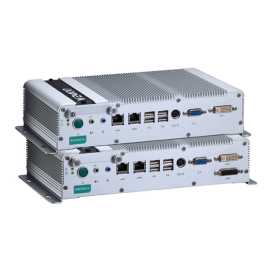
V2401/2402 HW User's Manual Hardware Introduction Appearance V2401/2402 Front View V2401/2402 Rear View Dimensions... -
Page 12: Led Indicators
Real Time Clock The embedded computer’s real-time clock is powered by a lithium battery. We strongly recommend that you NOT replace the lithium battery on your own. If the battery needs to be changed, please contact the Moxa RMA service team. -
Page 13: Hardware Connection Description
Hardware Connection Description In this chapter, we show how to connect the embedded computers to the network and to various devices. The following topics are covered in this chapter: Installing the V2401/2402 Wiring Requirements Connecting the Power ... -
Page 14: Installing The V2401/2402
It includes two DIN-rail brackets and eight screws. To attach the DIN-rail kit, turn the V2401/2402 over to the bottom cover. Find the locations for the screws and place the brackets on the cover. Please note that all eight screws must be firmly attached so that the computer... - Page 15 V2401/2402 HW User's Manual Hardware Connection Description When the brackets are firmly attached with the screws, it can be installed on a DIN-rail To release the DIN-rail kit, simply use a screwdriver to push down the lower part. Please use at least two persons to do this step as once the DIN-rail kit is pushed down, the computer will be detached immediately from the DIN-rail.
- Page 16 VESA Mounting (not included in the Package) The V2401/2402 has four screw holes on the bottom panel for attaching the computer to a 100 x 100 mm VESA mounting kit. Use four screws to attach the computer to the VESA mounting kit.
-
Page 17: Wiring Requirements
It is advisable to label the wiring to all devices in the system. ATTENTION Safety First! Be sure to disconnect the power cord before installing and/or wiring your V2401/2402. Wiring Caution! Calculate the maximum possible current in each power wire and common wire. Observe all electrical codes dictating the maximum current allowable for each wire size. -
Page 18: Connecting Data Transmission Cables
RxDA(-) DataA(-) The V2401 also includes an RS-232 connector on the front panel. It can connect eight devices with a 68-pin VHDC cable. This cable must be purchased separately. Simply connect one end of the connector to the V2401, and connect the other end to eight serial devices. -
Page 19: Installing A Compactflash Card
V2401/2402 HW User's Manual Hardware Connection Description Installing a CompactFlash Card The V2401/2402 embedded computers come with a CompactFlash socket. To insert a CompactFlash card, follow these instructions: 1. Disconnect the V2401/2402 from its power source. 2. The CompactFlash socket is located on the left side of the front panel. Unscrew the CompactFlash socket cover. -
Page 20: Connecting A Ps/2 Keyboard And Mouse
ATTENTION Please note that without a Y-type cable, the PS/2 connector on the V2401/2402 can only work with a PS/2 keyboard. A PS/2 mouse will not function when directly connected to the PS/2 connector on the V2401/2402... -
Page 21: Connecting To The Usb Device
Connecting to the USB Device The V2401/2402 comes with 6 USB 2.0 hosts. Four are located on the front panel and the other two are on the rear panel. The hosts can be used for an external flash disk or hard drive for storing large amounts of data. You can also use these USB hosts to connect to a keyboard or a mouse. -
Page 22: Connecting To A Vga Monitor
DDC2B Clock Connecting to an LVDS Monitor The V2401 also comes with a 26-pin LVDS connector on the front panel to connect a panel with an LVDS cable. The pin assignments of the LVDS connector are shown below. LVDS Female Connector Pin No. -
Page 23: Connecting To A Dvi-I Monitor
Connecting to a DVI-I Monitor The V2401/2402 computers come with a DVI-I connector that can connect to a DVI monitor. Use the cable to connect one end to the DVI-I connector and the other end to the monitor. See the following table for DVI-I connector pin assignments. -
Page 24: Upgrading The Memory Module
Hardware Connection Description Upgrading the Memory Module The V2401/2402 embedded computers support one 200-pin DDR2 533 SODIMM module of up to 2GB. One DDR2 SDRAM memory module is installed at the factory. To upgrade the DDR2 SDRAM memory module, follow these instructions: Disconnect the V2401/2402 from the power source. -
Page 25: Upgrade The Dom Module
When finished, replace the back cover of the computer. Upgrade the DOM Module The V2401/2402 has been pre-installed with a DOM to store the OS. To upgrade the DOM module, see the following steps. After taking off the back cover of the V2401/2402, find the location of the DOM module socket. -
Page 26: Installing A Sata Hard Disk
Insert the new DOM module; make sure it is firmly inserted. Installing a SATA Hard Disk The V2401/2402 embedded computers have one SATA connector for installing a SATA hard disk. To install a 2.5-inch SATA hard disk, follow these instructions. - Page 27 V2401/2402 HW User's Manual Hardware Connection Description 3. Place the hard drive disk on the bracket and use four screw to attach it. 4. When finished, place the bracket on the main board and find the location for attachment. 5. Make sure that four screws have been securely attached on the main board. Then use the SATA cable to connect the hard drive disk to the SATA connector, and use the power cable to connect to the power connector.
-
Page 28: Bios Setup
BIOS Setup This chapter describes the BIOS settings of the V2401/2402 embedded computers. The BIOS is a set of input/output control routines for peripherals. The BIOS is used to initialize basic peripherals and helps boot the operating system before the operating system is loaded. The BIOS setup allows the user to modify the system configurations of these basic input/output peripherals. -
Page 29: Entering The Bios Setup Utility
V2401/2402 HW User's Manual BIOS Setup Entering the BIOS Setup Utility To enter the BIOS setup utility, press the “Del” key while the system is booting up. The main BIOS Setup screen will appear. A basic description of each function key is listed at the bottom of the screen. Refer to these descriptions to learn how to scroll about the screen, how to select by pressing “Enter,”... -
Page 30: System Security
V2401/2402 HW User's Manual BIOS Setup System Security To set up system security, select the “Security” option under “Main” to bring up the following screen. This menu includes two options: “Set Password” and “Security Option.” When you select the Set Password option, a pop-up “Enter Password:” window will appear on the screen. The password that you type will replace the password stored in the CMOS memory. -
Page 31: Advanced Settings
V2401/2402 HW User's Manual BIOS Setup Advanced Settings The “Advanced Features” screen will appear when choosing the “Advanced” item from the main menu. Hard Disk Boot Priority First/Second/Third Boot Device This option allows users to select or change the device boot priority. You may set 3 levels of priority to determine the boot up sequence for different bootable devices, such as a hard drive, CD-ROM, and removable devices. -
Page 32: Cpu Features
V2401/2402 HW User's Manual BIOS Setup CPU Features C1E Function This item allows you to configure the power-saving mode when the CPU is in C1 status. Options: Auto (default), Disabled EIST Function This item allows you to configure the power saving mode with the Enhanced Intel SpeedStep Technology. This helps the system reduce the workload frequency and power consumption. -
Page 33: On-Chip Frame Buffer Size
V2401/2402 HW User's Manual BIOS Setup On-chip Frame Buffer Size This item determines the frame buffer size for the VGA function, and will share the system memory. Options: 1 MB, 4 MB, 8 MB (default), DVMT Mode Sets the Dynamic Video Memory Technology operating mode. When set to “Fixed,” the graphics driver will reserve a fixed portion of the system memory as graphics memory. -
Page 34: Peripherals
V2401/2402 HW User's Manual BIOS Setup Peripherals OnChip IDE Device On-Chip Channel 0 PCI IDE This item allows you to enable or disable the Channel 0 onboard PCI device. Options: Enabled (default), Disabled IDE Channel 0 Master UDMA This item allows you to configure UDMA mode for the device on IDE channel 0 Master. -
Page 35: On-Chip Channel 1 Pci Ide
V2401/2402 HW User's Manual BIOS Setup On-Chip Channel 1 PCI IDE This item allows you to enable or disable the Channel 1 onboard PCI device. Options: Enabled (default), Disabled IDE Channel 1 Master UDMA This item allows you to configure UDMA mode for the device on IDE channel 1 Master. -
Page 36: Super I/O Device
Super I/O Device Debug Port This function allows you to enable/disable the debug port communication. The V2401/2402 computer will automatically distribute the IRQ value for the debug port as the default value. If you wish to disable, select Disabled. This port is only for engineers who are debugging programs. -
Page 37: Acpi Suspend Type
V2401/2402 HW User's Manual BIOS Setup ACPI Suspend Type This item allows you to set up the ACPI suspend type for power management function. Option: S1 (POS), (default), S3 (STR) Soft-Off by PWR-BTTN This item determines the delay to stop the software when pushing the power button. -
Page 38: Load Defaults
V2401/2402 HW User's Manual BIOS Setup Load Defaults Load System Default Settings Use this option to load system factory default settings instead of the current BIOS settings. This option is useful for when the system is unstable. Users do not need to remember what settings were active before the system fails. -
Page 39: Save & Exit Setup
This section describes how to upgrade the BIOS. However, please note that upgrading the BIOS involves high risk of damage to your computer. We strongly recommend that you contact Moxa’s TS staff for assistance and obtain all necessary tools and files before attempting to upgrade. - Page 40 Prepare the Upgrade Tool and BIOS Binary File. You must use the BIOS upgrade installation file to upgrade the BIOS. You can send your request to Moxa's technical support team at support@moxa.com to get an updated version of the BIOS.
- Page 41 V2401/2402 HW User's Manual BIOS Setup 7. Select Exit Save & Exit Setup and then press Enter. 8. Choose Y to save to the CMOS and then exit. Step 4: Run awdflash.exe to upgrade the BIOS. 1. While in the BIOS Setup menu and before upgrading the BIOS, you may choose to save the old BIOS files to a specific location.
-
Page 42: Regulatory Approval Statement
Regulatory Approval Statement This device complies with part 15 of the FCC Rules. Operation is subject to the following two conditions: (1) This device may not cause harmful interference, and (2) this device must accept any interference received, including interference that may cause undesired operation.
Need help?
Do you have a question about the V2401 and is the answer not in the manual?
Questions and answers