Moxa Technologies V2201 Quick Installation Manual
Hide thumbs
Also See for V2201:
- Quick installation manual (11 pages) ,
- Hardware user manual (40 pages)
Table of Contents
Advertisement
Quick Links
Quick Installation Guide
Moxa Americas:
Toll-free: 1-888-669-2872
Tel:
1-714-528-6777
Fax:
1-714-528-6778
Moxa Europe:
Tel:
+49-89-3 70 03 99-0
Fax:
+49-89-3 70 03 99-99
Moxa India:
Tel:
+91-80-4172-9088
Fax:
+91-80-4132-1045
Edition 1.0, October 2015
Technical Support Contact Information
www.moxa.com/support
2015 Moxa Inc. All rights reserved.
V2201
Moxa China (Shanghai office):
Toll-free: 800-820-5036
Tel:
+86-21-5258-9955
Fax:
+86-21-5258-5505
Moxa Asia-Pacific:
Tel:
+886-2-8919-1230
Fax:
+886-2-8919-1231
P/N: 1802022010010
*1802022010010*
Advertisement
Table of Contents

Related Manuals for Moxa Technologies V2201


Summary of Contents for Moxa Technologies V2201
- Page 1 V2201 Quick Installation Guide Edition 1.0, October 2015 Technical Support Contact Information www.moxa.com/support Moxa Americas: Moxa China (Shanghai office): Toll-free: 1-888-669-2872 Toll-free: 800-820-5036 Tel: 1-714-528-6777 Tel: +86-21-5258-9955 Fax: 1-714-528-6778 Fax: +86-21-5258-5505 Moxa Europe: Moxa Asia-Pacific: Tel: +49-89-3 70 03 99-0...
-
Page 2: Package Checklist
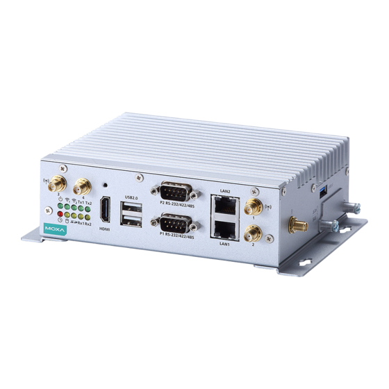
NOTE: Please notify your sales representative if any of the above items are missing or damaged. V2201 Panel Layout The following figures show the panel layouts of the V2201-W series; for “non-W” series, the 5 antenna connectors will not be installed during production. - Page 3 Left Side View LED Indicators The following table describes the LED indicators located on the front panel of the V2201. LED Name Status Function Power Green Power is on and computer is functioning normally. Power is off User Defined Event has occurred...
-
Page 4: Installing The Wireless Modules
5 wireless SMA connectors installed during the production process. The V2201 has two mini-PCIe sockets on the bottom panel. One socket supports USB signals only, using the MC9090, MC7354, or MC7354 mini-PCIe cards. Another socket supports standard USB + PCIe signals. -
Page 5: Installation
Installing the V2201 DIN-Rail Mounting The DK-DC50131 die-cast metal kit must be bought separately. The kit enables easy and robust installation of the V2201. Use 4 screws to attach the DIN-rail mounting kit tightly to the side panel of the V2201. Installation:... -
Page 6: Connector Description
Connector Description Power Connector Connect the 9 to 36 VDC LPS or Class 2 power line to the V2201’s terminal block. If the power is supplied properly, the Power LED will light up. The OS is ready when the Ready LED glows a solid green. - Page 7 SG wire to an appropriate grounded metal surface. HDMI Outputs The V2201 comes with a type A HDMI female connector on the front panel to connect an HDMI monitor. The screw hole above the HDMI connector is used to attach a custom lock to the HDMI connector;...
- Page 8 USIM card into the slot. USB Hosts The V2201 has 1 USB 3.0 and 2 USB 2.0 Type A connectors. 2 USB 2.0 ports are located on the front panel, and 1 USB 3.0 port is on the right panel.
-
Page 9: Configuring The Ethernet Interface
Powering on the V2201 To power on the V2201, connect the “terminal block to power jack converter” to the V2201’s DC terminal block (located on the side panel), and then connect the 9 to 36 VDC power adapter. Press the Power Button to turn on the computer. - Page 10 NOTE Refer to the V2201 user’s manuals for other configuration information. - 10 -...
Need help?
Do you have a question about the V2201 and is the answer not in the manual?
Questions and answers