Table of Contents
Advertisement
Advertisement
Table of Contents

Related Manuals for Aruba Networks Access Point Aruba AP 60/61


Summary of Contents for Aruba Networks Access Point Aruba AP 60/61
- Page 1 Aruba AP 60/61 Access Point Installation Guide...
-
Page 2: Legal Notice
Copyright © 2005 Aruba Wireless Networks, Inc. All rights reserved. Trademarks Aruba Networks and Aruba The Mobile Edge Company are trademarks of Aruba Wireless Networks, Inc. Specifications are subject to change without notice. Sygate On-Demand Agent and Sygate Enforcer are trademarks of Sygate Technologies. -
Page 3: Table Of Contents
Contents Introduction ..........Chapter 1 . - Page 4 Related Documents Text Conventions Contacting Aruba Networks Proper Disposal of Aruba Equipment Notes ........... .
-
Page 5: Chapter 1 Introduction
Introduction The Aruba AP 60/61 is part of a comprehensive wireless network solution. The device works in conjunction with the Aruba Mobility Controller and can act as a wireless access point or air monitor. As a wireless Access Point (AP), the Aruba AP 60/61 provides transparent, secure, high-speed data communications between wireless network devices (fixed, portable, or mobile computers with IEEE 802.11a or IEEE 802.11b/g wireless adapters) and the wired LAN. -
Page 6: Front View
Introduction Chapter 1 Front View Aruba AP 60/61 Front View IGURE Antenna fixtures for Wireless Communications Depending on the model, the AP will have one of the following: Aruba AP 60/61 Installation Guide 0500160 December 2005... - Page 7 Aruba AP60–Two Reverse Polarity SMA (RP-SMA) connectors for attaching separate antennas (not included). For details, see Antennas” page ArubaOS 2.2 releases or lower. Single antenna operation is supported with ArubaOS 2.3 or higher.) When facing the A60 as shown in on the left is for antenna 1, and the connector on the right is for antenna 2 in a diversity configuration.
- Page 8 Introduction Chapter 1 FE Port This port attaches the Aruba AP 60/61 to a 10Base-T/100Base-TX (twisted-pair) Ethernet LAN segment. This port also supports Serial and Power Over Ethernet (SPOE). Appendix C, “Product Specifications.” DC Power Socket This socket is used to connect the optional AC power adapter (not included). If POE is being used to supply power to the Aruba AP 60/61, the power adapter is not necessary.
-
Page 9: Back View
Back View Aruba AP 60/61 Back View IGURE Mounting Slots The keyhole-shaped slots on the back of the chassis are used for mounting the Aruba AP 60/61. Air Vents These vents promote proper air circulation for cooling the device. Do not allow these vents to be obstructed by mounting equipment, network cables, or any other material. -
Page 10: The Aruba Ap Setup Process
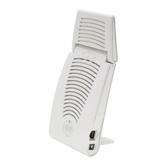
Introduction Chapter 1 Fold-Out Stand This fold-out stand allows the Aruba AP 60/61 to be stood upright on a table or shelf. Kensington Security Slot This slot is compatible with a Kensington MicroSaver Security Cable (not included) which can be used to prevent the unauthorized removal of the Aruba AP 60/61 from its installed location. -
Page 11: Provisioning Access Points
Specifically, Access Points must use channel assignment and antenna gain settings (for detachable antennas) appropriate to the location in which the Access Point will be used. Aruba Networks, in compliance with governmental requirements, has designed the AP60 and AP61 such that only authorized network administrators can change these settings. -
Page 12: Aruba Discovery Protocol
Provisioning Access Points Chapter 2 Each of these three methods is explained in the following sections. Use these procedures for initial provisioning of APs. To change the configuration for APs that have already been provisioned, go to See the ArubaOS User Guide for more information on reprovisioning existing APs. When an AP60 powers up for the first time, the Mobility AUTION Controller will recognize that it is detachable-antennas... -
Page 13: Ap Reprovisioning
enabled on the network, the Aruba Mobility Controllers need to be on the same broadcast domain as the AP or an “IP Helper” must be configured to direct the broadcast ADP packets to the Aruba Mobility Controller. Once these discovery prerequisites are met, the Mobility Controller will respond to APs with the IP address of the Master Aruba switch. - Page 14 Provisioning Access Points Chapter 2 Provisioning Tab IGURE Configure the APs Subnet and Netmask. This is the subnet from which the AP gets an IP during provisioning. (This is not the IP address the AP will use when deployed. The provisioning subnet should be not be the same as an existing subnet on Mobility Controller.) Select the Port or Port range for provisioning.
- Page 15 Port Range Screen IGURE Specify the Aruba AP 60/61-specific parameters. Configure the gain value appropriate for the location in which this AP will be deployed. (See Table 3-1 If the AP being provisioned is a model with detachable antenna capability (such as an Aruba AP-60), enter the antenna gain in dBi(e.g., 4.0).
-
Page 16: Manual Provisioning
(Provisioned). Check that the configured parameters are reflected in the AP list entry. Aruba Networks recommends that you provision each AP for a unique location as suggested by site-survey planning. Label each AP with this location information and place the AP in its proper location. Failure to place APs in the location for which they were provisioned will reduce the effectiveness of such RF features as triangulation. - Page 17 An Aruba serial breakout adapter kit, Part Number CA-SPOE-ADAPT-3, (not included). (See “Connecting the Console Terminal” Access to the Aruba AP 60/61 FE port through one of the following: Direct contact with the AP , or If the AP is already deployed, you must have access to the end of the FE cable that leads directly to the AP with no intervening hubs, routers, or other networking equipment.
-
Page 18: Connecting The Console Terminal
Provisioning Access Points Chapter 2 Connecting the Console Terminal Manual provisioning requires this procedure. You must use the serial console breakout adapter cable to be able to access the serial console interface to the Aruba AP 60/61 while allowing the device to be powered by the AC adapter or POE (from an Aruba Mobility Controller). - Page 19 The LAN connection is optional unless POE is being used to power the AP . For convenience, the adapter kit includes an FE coupler to connect RJ-45 cable ends together. Connect power to the Aruba AP 60/61. Be sure to comply with electrical grounding standards AUTION during all phases of installation and operation of the AP .
- Page 20 Provisioning Access Points Chapter 2 Depending on the Aruba AP 60/61 status, you will see one of the following on your terminal: Autoboot countdown—The countdown prompt allows you to interrupt the normal startup process and access the apboot prompt where provisioning is performed.
-
Page 21: Setting Aruba Ap 60/61 Parameters
Setting Aruba AP 60/61 Parameters From the apboot prompt, configure the host information, if necessary. In order to provide centralized management of the APs, each Aruba AP downloads its software image and configuration files from a master Mobility Controller. Setting the correct host information depends on the following: Does your network use direct IP addresses or DNS with host names? If using host names, is aruba-master acceptable for the master Mobility Con- troller, or do you need to define a different name? - Page 22 Provisioning Access Points Chapter 2 The master and serverip environment variables also affect how source files are selected and should be cleared when using this approach. To clear a variable, enter the setenv variable command with no host or address value. When finished, proceed to Step 2.
- Page 23 where the following fields are required: Building Number A unique number (1-254) is required for each building in your campus. Floor Number Within any building, a unique number (1-254) is required for each floor. Device Number Within any floor, a unique number (1-65534) is required for each access point or air monitor.
- Page 24 Provisioning Access Points Chapter 2 Aruba AP 60/61 Installation Guide 0500160 December 2005...
-
Page 25: Chapter 3 Ap Deployment
AP Deployment This chapter covers the following topics: Physical mounting of the Aruba AP 60/61 Connecting the required cables Mounting the Aruba AP 60/61 When provisioning is complete, mount the Aruba AP 60/61 at its intended service location. The Aruba AP 60/61 Access Points with or without external antennas are intended only for installation in Environment A as defined in IEEE 802.3.af. -
Page 26: Aruba 60 Detachable Antennas
AP Deployment Chapter 3 The Aruba AP 60/61 can be mounted on a wall or suspended from above (not shown) using one of the optional mounting kits (dimensions vary) in the following ways: Aruba AP 60/61 Mounting Options IGURE For dimensions, see cm (2") additional space on the right-hand side for cables. - Page 27 FCC-Approved Detachable Antennas Table 3-1 lists the antennas which are approved for use with the Aruba 60. FCC-Approved Detachable Antennas ABLE Aruba Part # Description MULTI-BAND ANTENNA AP-ANT-1 Tri-Band, High-Gain, Omni-Directional Antenna (Indoor) (Swivel Connector) 2.4Ghz (802.11B/G) AP-ANT-2 High-Gain, Omni-Directional Cylindrical (Indoor) with RP-SMA Connector...
- Page 28 AP Deployment Chapter 3 FCC-Approved Detachable Antennas (Continued) ABLE AP-ANT-8 High-Gain, Omni-Directional Cylindrical (Indoor / Outdoor) with RP-SMA Connector 5Ghz (802.11A) AP-ANT-10 High-Gain, Omni-Directional Cylindrical (Indoor / Outdoor) with RP-SMA Connector AP-ANT-11 Down-Tilt, Omni-Directional Patch Antenna (Indoor) with RP-SMA Connector AP-ANT-12 High-Gain, Directional Patch...
-
Page 29: Free-Standing Placement
Free-Standing Placement To place the Aruba AP 60/61 indoors on a flat table or shelf: Flip open the stand located on the back of the Aruba AP 60/61: Aruba AP 60/61Fold-Out Stand IGURE Place the device on a sturdy table or shelf. Do not place the Aruba AP 60/61 in any place where it AUTION could fall on people or equipment. -
Page 30: Using The Built-In Mounting Slots
AP Deployment Chapter 3 Using the Built-In Mounting Slots The keyhole-shaped slots on the back of the Aruba AP 60/61 can be used to attach the device upright to an indoor wall or shelf. Do not use the mounting slots to hang the Aruba AP AUTION 60/61 from the ceiling, sideways, or in any place where it could fall on people or equipment. -
Page 31: Using The Optional Mounting Kits
Align the Aruba AP 60/61 mounting slots to capture the surface screws. Hanging the Aruba AP 60/61 on Screws IGURE Secure the Aruba AP 60/61, if desired. To prevent the unauthorized removal of the Aruba AP 60/61 from its installed location, use a Kensington MicroSaver Security Cable (not included). -
Page 32: Connecting Required Cables
AP Deployment Chapter 3 Connecting Required Cables The Aruba AP 60/61 Access Points with or without external antennas are intended only for installation in Environment A as defined in IEEE 802.3.af. All interconnected equipment must be contained within the same building, including the interconnected equipment's associated LAN connections. -
Page 33: Connecting Cables & Power
Connecting Cables & Power To prevent personal injury or damage to equipment, be AUTION sure to comply with electrical grounding standards during all phases of installation and operation of the AP . Do not allow the Aruba AP 60/61 or its attachments to be connected to or make contact with metal or power outlets on a different electrical ground than the device to which it is connected. -
Page 34: Selecting An Antenna
AP Deployment Chapter 3 Selecting an Antenna There are three ways to select an AP60 antenna: From the AP console (serial or telnet) enter set_antenna 0|1|2 where 0 specifies auto mode, and 1 or 2 chooses a specific antenna. The antenna selection is not persistent and the AP will loose the antenna selection, if rebooted. -
Page 35: Appendix A Troubleshooting
Troubleshooting This appendix discusses troubleshooting tools and procedures available for the Aruba AP 60/61. Troubleshooting should be limited to the information provided below. This AP contains no user accessible components. Do not AUTION attempt to disassemble the Aruba AP 60/61. If this AP does not operate properly, contact Aruba Technical Support (contact information is contained in “Troubleshooting”). -
Page 36: Direct Terminal Connection
Troubleshooting Appendix A Use a Telnet client on your management workstation to connect to theMobility Controller IP address using logical port 2300. The connection command may vary depending on the specific software used, but commonly appears as follows: telnet <Mobility Controller IP address> 2300 >... -
Page 37: Remote Telnet Connection
Press <Enter> a few times to establish communication between the Aruba AP 60/61 and terminal. If the AP has not finished booting, allow the Autoboot timer to expire. When the device has booted, the AP Support prompt (#) will appear. Aruba has two serial cables for the AP 60s. -
Page 38: Ap Support
Troubleshooting Appendix A AP Support Access Levels User Access User access is a low security level, featuring only the most basic commands. It is available without any additional login after the AP has booted. Privileged Access Privileged-level access requires the privileged password (the same privileged password used on the Mobility Controller) to be entered using the user level enable command. -
Page 39: Resetting The Ap To Factory Defaults
Resetting the AP to Factory Defaults In the event you need to reboot the Access Point with the configuration shipped from the factory, from the bootrom prompt, enter: purge save reset Break into the bootrom mode again and enter: save Troubleshooting Appendix A Aruba AP 60/61... - Page 40 Troubleshooting Appendix A Aruba AP 60/61 Installation Guide 0500160 December 2005...
-
Page 41: Appendix B Port Specifications
Port Specifications FE Port The 10/100 Mbps Ethernet (FE) port is located on the right-hand side of the Aruba AP 60/61 and has an RJ-45 female connector. The port pin-outs are shown in Figure B-1: Aruba 60/61 10/100 Mbps Ethernet Aruba AP 60/61 FE Port IGURE The appropriate cable depends on the level of connectivity required of the FE port:... -
Page 42: Serial Breakout Adapter
Port Specifications Appendix B Install cables in accordance with all applicable local regulations and practices. Serial Breakout Adapter The optional serial breakout adapter is used to separate the serial communications lines from the Aruba AP 60/61 FE+SPOE port. This allows the administrator to connect a local serial console directly to the AP and access the apboot prompt for manual provisioning. -
Page 43: To Ap" Specifications
“To AP” Specifications The RJ-45 connector labeled “To AP” attaches to the Aruba AP 60/61 FE port either directly (if the AP is physically available) or indirectly (if the AP is already deployed). When connecting indirectly, use a straight-through FE coupler to attach the “To AP”... - Page 44 Port Specifications Appendix B The Aruba AP 60/61 and serial breakout adapter are plenum rated. When is installed in an air-handling space, as described in NEC (2002) Article 300.22(C), the connecting FE cable should be suitable under NEC Article 800.50 and marked accordingly for use in plenums and air-handling spaces with regard to smoke propagation, such as CL2-P , CL3-P , MPP or CMP .
-
Page 45: Appendix C Product Specifications
Product Specifications Compliance This section lists compliance information on a country-by-country basis. United States The following compliance statements apply for use of this product in the United States. FCC - Class B This equipment has been tested and found to comply with the limits for a Class B digital device, pursuant to part 15 of the FCC Rules. -
Page 46: Canada
Product Specifications Appendix C RF Radiation Exposure Statement This equipment complies with FCC RF radiation exposure limits set forth for fixed indoor use only. This equipment should be installed and operated with a minimum distance of 38.5 centimeters (15.2 inches) between the radiator and your body for 2.4 GHz and 5 Ghz operations. -
Page 47: Japan
To reduce potential radio interference to other users, the antenna type and its gain should be so chosen that the equivalent isotropically radiated power (EIRP) is not more than that permitted for successful communication. Operation is subject to the following two conditions: (1) this device may not cause interference, and (2) this device must accept any interference, including interference that may cause undesired operation of the device. - Page 48 Product Specifications Appendix C Peut être utilisé dans des gaines transportant de l’air traité, conformément à la section 300-22(c) du National Electrical Code et aux articles 2-128, 12-010(3) et 12-100 du Code Canadien de l’électricité, Première partie, CSA C22.1. EMC Compliance and Warning Statement This equipment has been tested and found to comply with the limits of the standard for medical devices, IEC 60601-1-2:2001.
-
Page 49: Certifications
Certifications Item Measurement Electromagnetic FCC Part 15 Class B, FCC Part 15 Class C Compatibility (15.207/15.247) FCC Part 15 Class E 15.407 RSS 210 (CAN) ICES-003 Class B VCCI Class B TELEC ARIB STD-T66 AS/NZS 3548 Class B EN 61000-3, EN 61000-4-2, EN 61000-4-3, EN 61000-4-4, EN 61000-4-5, EN 61000-4-6, EN 61000-4-8, EN 61000-4-11, EN 55022, EN 55024 IEC 60601-1-2:2001(AP 60) -
Page 50: Product Label
Product Specifications Appendix C Product Label The product label is affixed to the chassis of the Aruba AP 60/61 The symbols on the label are explained in this chapter. Product Features Wireless dual-band transceiver Varied antenna options: The Aruba AP60 has dual Reverse Polarity SMA (RP-SMA) antenna connectors that accept a variety of high-gain detachable antennas (not included). -
Page 51: Power Over Ethernet
802.11b operation uses the IEEE 802.11 High-Rate Direct Sequence (HRDS) specification, and a shared collision domain (CSMA/CA). It operates in the 2.4GHz Industrial/Scientific/Medical (ISM) band. The ISM band is available worldwide for unlicensed use. Data is transmitted at speeds of up to 11 Mbps. -
Page 52: Aruba Ap-60 Access Point
Product Specifications Appendix C Serial breakout adapter for direct access to the AP console Mounting kit (modular cradle for walls and suspended ceilings) Check with your Aruba sales representative for the availability of optional items. The following specifications apply to the Aruba AP60 and Aruba AP61 Access Points. - Page 53 AP-60 802.11 Specifications ABLE Description 802.11a Antenna Dual, diversity supporting Reverse Polarity-SMA (RP-SMA) detachable antenna interfaces suitable for acceptance of single-band or tri-band 802.11a/b/g detachable antennas of various pattern types and gain. For information on third-party antennas, go to the Interoperability section of the Products page at: http://www.arubanetworks.com Frequency...
- Page 54 Product Specifications Appendix C ABLE Description 802.11a Media CSMA/CA with Access Control Operating Channels Complete country list available at http:// www.arubanetw orks.com/produc ts/aps/certificatio Data Rates 6, 9, 12, 18, 24, 36, 48, 54 Mbps per channel Aruba AP 60/61 Installation Guide AP-60 802.11 Specifications 802.11b CSMA/CA with...
- Page 55 AP-60 Characteristics ABLE Description Maximum Clients Multi-mode Selectable via software Radio Band Management of all 802.11 parameters Manageability: Network Wide AP Management via: WEB GUI SNMPv3 Access Point Profiles, Management by: Geographical Location BSSID Radio Type Encryption 40bit / 64bit / 128bit / 152bit WEP , TKIP , AES Support (AP and Mobility Controller)
- Page 56 Product Specifications Appendix C ABLE Description Power Power Requirements Output Power Power Consumption Operating Environment Storage Environment Humidity Altitude Standards Compliance Mains Connections Protection Against Egress of Water Aruba AP 60/61 Installation Guide AP-60 Characteristics Optional AC Power Adapter Input— 100-240 AC, 50-60 Hz Access Point Input—...
-
Page 57: Aruba Ap-61 Access Point
ABLE Description Mode of Operation a. Measurements indicate only the Access Point chassis. Size and weight do not include other materials (such as detachable antennas, mounting kits, and cables) which may vary Aruba AP-61 Access Point IGURE AP-60 Characteristics As defined by IEC 60601-1, this unit is considered “Continuous Operation”... - Page 58 Product Specifications Appendix C ABLE Description 802.11a Antenna Integral, diversity supporting dual, tri-band 802.11a/b/g omni-directional high-gain antennas with 90 degrees rotational movement Integral antenna gain: 2.4 Ghz / 2.8dBi 5.150-5.350 Ghz / 3.9dBi 5.6 Ghz / 4 dBi Frequency Band Radio Orthogonal Technology...
- Page 59 AP-61 802.11 Specifications (Continued) ABLE Description 802.11a Operating US, Canada & ETSI: 12 Channels Japan: 5 Complete country list available at http:// www.arubanetw orks.com/produc aps/certification Data Rates 6, 9, 12, 18, 24, 36, 48, 54 Mbps per channel AP-61 Characteristics ABLE Description Maximum...
- Page 60 Product Specifications Appendix C ABLE Description Encryption Support (AP and Mobility Controller) Physical (HxWxD): Interfaces (Electrical): Interfaces (Mechanical): Visual Indicators (LEDs) Power Power Requirements Aruba AP 60/61 Installation Guide AP-61 Characteristics (Continued) 40bit / 64bit / 128bit / 152bit WEP , TKIP , AES Antenna up, stand closed—216 x 99 x 31 mm / 8.50 x 3.90 x 1.22 in Antenna up, stand open—209 x 99 x 74 mm /...
-
Page 61: Related Documents
ABLE Description Output Power Power Consumption Operating Environment Storage Environment Humidity Altitude Standards Compliance Measurements indicate only the Access Point chassis. Size and weight do not in- clude other materials (such as detachable antennas, mounting kits, and cables) which may vary Related Documents The following items are part of the complete documentation for the Aruba system:... -
Page 62: Text Conventions
Product Specifications Appendix C Text Conventions The following conventions are used throughout this manual to emphasize important concepts: ABLE Type Style Description Italics This style is used to emphasize important terms and to mark the titles of books. System items This fixed-width font depicts the following: Commands In the command examples, this bold font depicts text... - Page 63 Product Specifications Appendix C Text Conventions (Continued) ABLE Useful tips or information about the topic under discussion. Indicates that protection against electrical shock is required. This symbol indicates that a danger to personal safety exists. Indicates caution is required. Failure to heed these cautions may result in damaged equipment or loss of data.
-
Page 64: Contacting Aruba Networks
Product Specifications Appendix C Contacting Aruba Networks Web Site Main Site http://www.arubanetworks.com Support http://www.arubanetworks.com/support E-mail Sales sales@arubanetworks.com Support support@arubanetworks.com Telephone Numbers Main 408-227-4500 408-227-4550 Sales 408-754-1201 Support In the US: 800-WI-FI-LAN (800-943-4526)+ France: 33 (0) 170725559+44 (0) 2071275989+49 (0) Germany:... -
Page 65: Proper Disposal Of Aruba Equipment
Product Specifications Appendix C Proper Disposal of Aruba Equipment This product at end of life is subject to separate collection and treatment in the EU Member States, Norway, and Switzerland and therefore is marked with the symbol shown at the left. Treatment applied at end of life of these products in these countries shall comply with the applicable national laws implementing Directive 2002/96EC on Waste of Electrical and... - Page 66 Product Specifications Appendix C Aruba AP 60/61 Installation Guide 0500160 December 2005...
-
Page 67: Notes
Notes Aruba AP 60/61 Installation Guide... - Page 68 Notes c r o s s m a n a v e n u e s u n n y v a l e c a l i f o r n i a 1 3 2 2 t e l f a x 4 0 8 2 2 7 4 5 0 0 4 0 8 2 2 7 4 5 5 0...
Need help?
Do you have a question about the Access Point Aruba AP 60/61 and is the answer not in the manual?
Questions and answers